
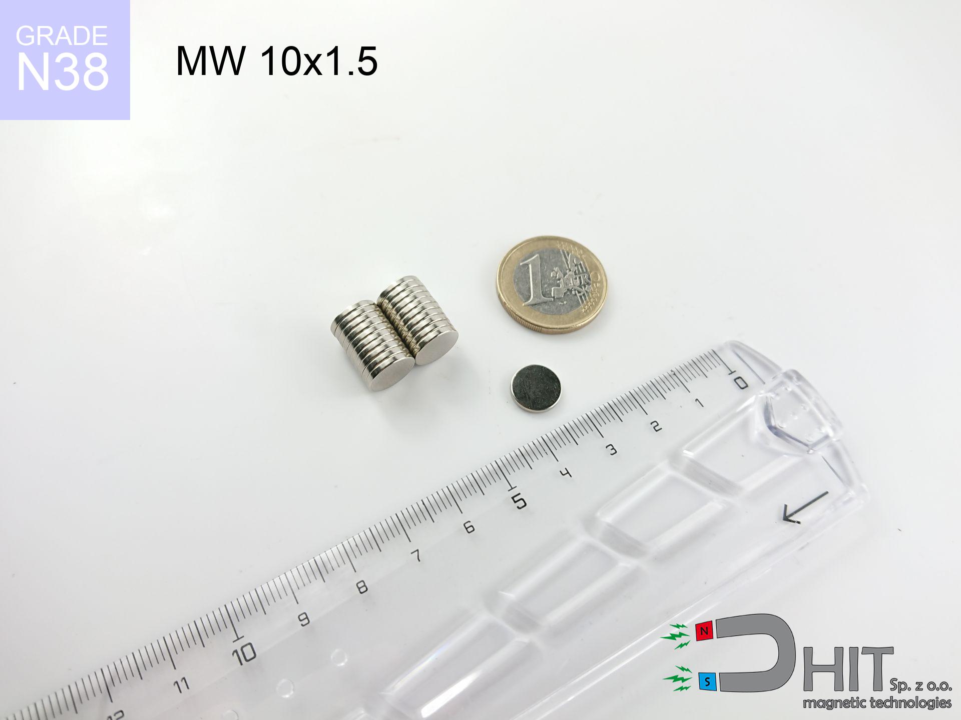
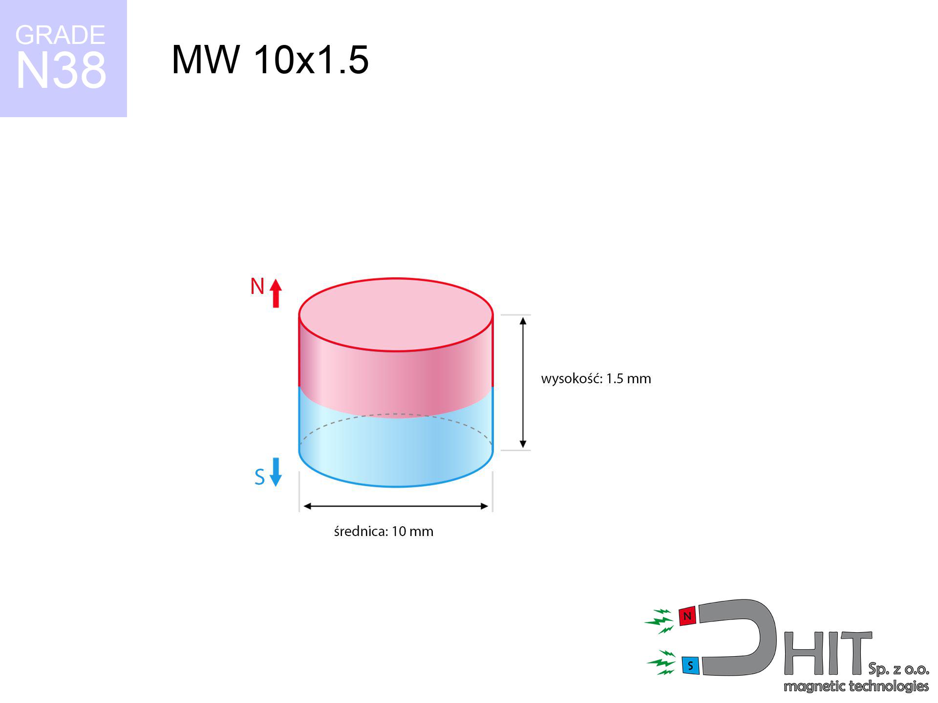
MW 10x1.5 / N38 - cylindrical magnet
cylindrical magnet
Catalog no 010003
GTIN/EAN: 5906301810001
Diameter Ø
10 mm [±0,1 mm]
Height
1.5 mm [±0,1 mm]
Weight
0.88 g
Magnetization Direction
↑ axial
Load capacity
0.82 kg / 8.01 N
Magnetic Induction
178.06 mT / 1781 Gs
Coating
[NiCuNi] Nickel
0.431 ZŁ with VAT / pcs + price for transport
0.350 ZŁ net + 23% VAT / pcs
bulk discounts:
Need more?
Give us a call
+48 888 99 98 98
or drop us a message via
form
our website.
Parameters along with form of a magnet can be estimated with our
magnetic mass calculator.
Orders placed before 14:00 will be shipped the same business day.
Technical of the product - MW 10x1.5 / N38 - cylindrical magnet
Specification / characteristics - MW 10x1.5 / N38 - cylindrical magnet
| properties | values |
|---|---|
| Cat. no. | 010003 |
| GTIN/EAN | 5906301810001 |
| Production/Distribution | Dhit sp. z o.o. |
| Country of origin | Poland / China / Germany |
| Customs code | 85059029 |
| Diameter Ø | 10 mm [±0,1 mm] |
| Height | 1.5 mm [±0,1 mm] |
| Weight | 0.88 g |
| Magnetization Direction | ↑ axial |
| Load capacity ~ ? | 0.82 kg / 8.01 N |
| Magnetic Induction ~ ? | 178.06 mT / 1781 Gs |
| Coating | [NiCuNi] Nickel |
| Manufacturing Tolerance | ±0.1 mm |
Magnetic properties of material N38
| properties | values | units |
|---|---|---|
| remenance Br [min. - max.] ? | 12.2-12.6 | kGs |
| remenance Br [min. - max.] ? | 1220-1260 | mT |
| coercivity bHc ? | 10.8-11.5 | kOe |
| coercivity bHc ? | 860-915 | kA/m |
| actual internal force iHc | ≥ 12 | kOe |
| actual internal force iHc | ≥ 955 | kA/m |
| energy density [min. - max.] ? | 36-38 | BH max MGOe |
| energy density [min. - max.] ? | 287-303 | BH max KJ/m |
| max. temperature ? | ≤ 80 | °C |
Physical properties of sintered neodymium magnets Nd2Fe14B at 20°C
| properties | values | units |
|---|---|---|
| Vickers hardness | ≥550 | Hv |
| Density | ≥7.4 | g/cm3 |
| Curie Temperature TC | 312 - 380 | °C |
| Curie Temperature TF | 593 - 716 | °F |
| Specific resistance | 150 | μΩ⋅cm |
| Bending strength | 250 | MPa |
| Compressive strength | 1000~1100 | MPa |
| Thermal expansion parallel (∥) to orientation (M) | (3-4) x 10-6 | °C-1 |
| Thermal expansion perpendicular (⊥) to orientation (M) | -(1-3) x 10-6 | °C-1 |
| Young's modulus | 1.7 x 10⁴ | kg/mm² |
Technical simulation of the product - technical parameters
These data constitute the direct effect of a engineering calculation. Results rely on models for the material Nd2Fe14B. Operational performance might slightly differ from theoretical values. Treat these calculations as a reference point during assembly planning.
Table 1: Static force (pull vs distance) - power drop
MW 10x1.5 / N38
| Distance (mm) | Induction (Gauss) / mT | Pull Force (kg/lbs/g/N) | Risk Status |
|---|---|---|---|
| 0 mm |
1780 Gs
178.0 mT
|
0.82 kg / 1.81 LBS
820.0 g / 8.0 N
|
safe |
| 1 mm |
1557 Gs
155.7 mT
|
0.63 kg / 1.38 LBS
627.2 g / 6.2 N
|
safe |
| 2 mm |
1253 Gs
125.3 mT
|
0.41 kg / 0.90 LBS
406.2 g / 4.0 N
|
safe |
| 3 mm |
958 Gs
95.8 mT
|
0.24 kg / 0.52 LBS
237.4 g / 2.3 N
|
safe |
| 5 mm |
530 Gs
53.0 mT
|
0.07 kg / 0.16 LBS
72.8 g / 0.7 N
|
safe |
| 10 mm |
140 Gs
14.0 mT
|
0.01 kg / 0.01 LBS
5.1 g / 0.1 N
|
safe |
| 15 mm |
52 Gs
5.2 mT
|
0.00 kg / 0.00 LBS
0.7 g / 0.0 N
|
safe |
| 20 mm |
24 Gs
2.4 mT
|
0.00 kg / 0.00 LBS
0.1 g / 0.0 N
|
safe |
| 30 mm |
8 Gs
0.8 mT
|
0.00 kg / 0.00 LBS
0.0 g / 0.0 N
|
safe |
| 50 mm |
2 Gs
0.2 mT
|
0.00 kg / 0.00 LBS
0.0 g / 0.0 N
|
safe |
Table 2: Vertical load (vertical surface)
MW 10x1.5 / N38
| Distance (mm) | Friction coefficient | Pull Force (kg/lbs/g/N) |
|---|---|---|
| 0 mm | Stal (~0.2) |
0.16 kg / 0.36 LBS
164.0 g / 1.6 N
|
| 1 mm | Stal (~0.2) |
0.13 kg / 0.28 LBS
126.0 g / 1.2 N
|
| 2 mm | Stal (~0.2) |
0.08 kg / 0.18 LBS
82.0 g / 0.8 N
|
| 3 mm | Stal (~0.2) |
0.05 kg / 0.11 LBS
48.0 g / 0.5 N
|
| 5 mm | Stal (~0.2) |
0.01 kg / 0.03 LBS
14.0 g / 0.1 N
|
| 10 mm | Stal (~0.2) |
0.00 kg / 0.00 LBS
2.0 g / 0.0 N
|
| 15 mm | Stal (~0.2) |
0.00 kg / 0.00 LBS
0.0 g / 0.0 N
|
| 20 mm | Stal (~0.2) |
0.00 kg / 0.00 LBS
0.0 g / 0.0 N
|
| 30 mm | Stal (~0.2) |
0.00 kg / 0.00 LBS
0.0 g / 0.0 N
|
| 50 mm | Stal (~0.2) |
0.00 kg / 0.00 LBS
0.0 g / 0.0 N
|
Table 3: Wall mounting (shearing) - vertical pull
MW 10x1.5 / N38
| Surface type | Friction coefficient / % Mocy | Max load (kg/lbs/g/N) |
|---|---|---|
| Raw steel |
µ = 0.3
30% Nominalnej Siły
|
0.25 kg / 0.54 LBS
246.0 g / 2.4 N
|
| Painted steel (standard) |
µ = 0.2
20% Nominalnej Siły
|
0.16 kg / 0.36 LBS
164.0 g / 1.6 N
|
| Oily/slippery steel |
µ = 0.1
10% Nominalnej Siły
|
0.08 kg / 0.18 LBS
82.0 g / 0.8 N
|
| Magnet with anti-slip rubber |
µ = 0.5
50% Nominalnej Siły
|
0.41 kg / 0.90 LBS
410.0 g / 4.0 N
|
Table 4: Steel thickness (substrate influence) - power losses
MW 10x1.5 / N38
| Steel thickness (mm) | % power | Real pull force (kg/lbs/g/N) |
|---|---|---|
| 0.5 mm |
|
0.08 kg / 0.18 LBS
82.0 g / 0.8 N
|
| 1 mm |
|
0.21 kg / 0.45 LBS
205.0 g / 2.0 N
|
| 2 mm |
|
0.41 kg / 0.90 LBS
410.0 g / 4.0 N
|
| 3 mm |
|
0.62 kg / 1.36 LBS
615.0 g / 6.0 N
|
| 5 mm |
|
0.82 kg / 1.81 LBS
820.0 g / 8.0 N
|
| 10 mm |
|
0.82 kg / 1.81 LBS
820.0 g / 8.0 N
|
| 11 mm |
|
0.82 kg / 1.81 LBS
820.0 g / 8.0 N
|
| 12 mm |
|
0.82 kg / 1.81 LBS
820.0 g / 8.0 N
|
Table 5: Working in heat (material behavior) - power drop
MW 10x1.5 / N38
| Ambient temp. (°C) | Power loss | Remaining pull (kg/lbs/g/N) | Status |
|---|---|---|---|
| 20 °C | 0.0% |
0.82 kg / 1.81 LBS
820.0 g / 8.0 N
|
OK |
| 40 °C | -2.2% |
0.80 kg / 1.77 LBS
802.0 g / 7.9 N
|
OK |
| 60 °C | -4.4% |
0.78 kg / 1.73 LBS
783.9 g / 7.7 N
|
|
| 80 °C | -6.6% |
0.77 kg / 1.69 LBS
765.9 g / 7.5 N
|
|
| 100 °C | -28.8% |
0.58 kg / 1.29 LBS
583.8 g / 5.7 N
|
Table 6: Two magnets (attraction) - field range
MW 10x1.5 / N38
| Gap (mm) | Attraction (kg/lbs) (N-S) | Shear Force (kg/lbs/g/N) | Repulsion (kg/lbs) (N-N) |
|---|---|---|---|
| 0 mm |
1.53 kg / 3.38 LBS
3 185 Gs
|
0.23 kg / 0.51 LBS
230 g / 2.3 N
|
N/A |
| 1 mm |
1.38 kg / 3.03 LBS
3 371 Gs
|
0.21 kg / 0.45 LBS
206 g / 2.0 N
|
1.24 kg / 2.73 LBS
~0 Gs
|
| 2 mm |
1.17 kg / 2.59 LBS
3 114 Gs
|
0.18 kg / 0.39 LBS
176 g / 1.7 N
|
1.06 kg / 2.33 LBS
~0 Gs
|
| 3 mm |
0.96 kg / 2.12 LBS
2 817 Gs
|
0.14 kg / 0.32 LBS
144 g / 1.4 N
|
0.86 kg / 1.91 LBS
~0 Gs
|
| 5 mm |
0.59 kg / 1.29 LBS
2 201 Gs
|
0.09 kg / 0.19 LBS
88 g / 0.9 N
|
0.53 kg / 1.16 LBS
~0 Gs
|
| 10 mm |
0.14 kg / 0.30 LBS
1 060 Gs
|
0.02 kg / 0.05 LBS
20 g / 0.2 N
|
0.12 kg / 0.27 LBS
~0 Gs
|
| 20 mm |
0.01 kg / 0.02 LBS
281 Gs
|
0.00 kg / 0.00 LBS
1 g / 0.0 N
|
0.00 kg / 0.00 LBS
~0 Gs
|
| 50 mm |
0.00 kg / 0.00 LBS
26 Gs
|
0.00 kg / 0.00 LBS
0 g / 0.0 N
|
0.00 kg / 0.00 LBS
~0 Gs
|
| 60 mm |
0.00 kg / 0.00 LBS
15 Gs
|
0.00 kg / 0.00 LBS
0 g / 0.0 N
|
0.00 kg / 0.00 LBS
~0 Gs
|
| 70 mm |
0.00 kg / 0.00 LBS
10 Gs
|
0.00 kg / 0.00 LBS
0 g / 0.0 N
|
0.00 kg / 0.00 LBS
~0 Gs
|
| 80 mm |
0.00 kg / 0.00 LBS
7 Gs
|
0.00 kg / 0.00 LBS
0 g / 0.0 N
|
0.00 kg / 0.00 LBS
~0 Gs
|
| 90 mm |
0.00 kg / 0.00 LBS
5 Gs
|
0.00 kg / 0.00 LBS
0 g / 0.0 N
|
0.00 kg / 0.00 LBS
~0 Gs
|
| 100 mm |
0.00 kg / 0.00 LBS
4 Gs
|
0.00 kg / 0.00 LBS
0 g / 0.0 N
|
0.00 kg / 0.00 LBS
~0 Gs
|
Table 7: Protective zones (implants) - precautionary measures
MW 10x1.5 / N38
| Object / Device | Limit (Gauss) / mT | Safe distance |
|---|---|---|
| Pacemaker | 5 Gs (0.5 mT) | 3.5 cm |
| Hearing aid | 10 Gs (1.0 mT) | 3.0 cm |
| Mechanical watch | 20 Gs (2.0 mT) | 2.5 cm |
| Phone / Smartphone | 40 Gs (4.0 mT) | 2.0 cm |
| Car key | 50 Gs (5.0 mT) | 2.0 cm |
| Payment card | 400 Gs (40.0 mT) | 1.0 cm |
| HDD hard drive | 600 Gs (60.0 mT) | 0.5 cm |
Table 8: Impact energy (kinetic energy) - warning
MW 10x1.5 / N38
| Start from (mm) | Speed (km/h) | Energy (J) | Predicted outcome |
|---|---|---|---|
| 10 mm |
30.91 km/h
(8.58 m/s)
|
0.03 J | |
| 30 mm |
53.32 km/h
(14.81 m/s)
|
0.10 J | |
| 50 mm |
68.84 km/h
(19.12 m/s)
|
0.16 J | |
| 100 mm |
97.35 km/h
(27.04 m/s)
|
0.32 J |
Table 9: Corrosion resistance
MW 10x1.5 / N38
| Technical parameter | Value / Description |
|---|---|
| Coating type | [NiCuNi] Nickel |
| Layer structure | Nickel - Copper - Nickel |
| Layer thickness | 10-20 µm |
| Salt spray test (SST) ? | 24 h |
| Recommended environment | Indoors only (dry) |
Table 10: Electrical data (Flux)
MW 10x1.5 / N38
| Parameter | Value | SI Unit / Description |
|---|---|---|
| Magnetic Flux | 1 717 Mx | 17.2 µWb |
| Pc Coefficient | 0.22 | Low (Flat) |
Table 11: Submerged application
MW 10x1.5 / N38
| Environment | Effective steel pull | Effect |
|---|---|---|
| Air (land) | 0.82 kg | Standard |
| Water (riverbed) |
0.94 kg
(+0.12 kg buoyancy gain)
|
+14.5% |
1. Vertical hold
*Note: On a vertical wall, the magnet holds just approx. 20-30% of its perpendicular strength.
2. Steel thickness impact
*Thin metal sheet (e.g. computer case) significantly weakens the holding force.
3. Thermal stability
*For standard magnets, the critical limit is 80°C.
4. Demagnetization curve and operating point (B-H)
chart generated for the permeance coefficient Pc (Permeance Coefficient) = 0.22
The chart above illustrates the magnetic characteristics of the material within the second quadrant of the hysteresis loop. The solid red line represents the demagnetization curve (material potential), while the dashed blue line is the load line based on the magnet's geometry. The Pc (Permeance Coefficient), also known as the load line slope, is a dimensionless value that describes the relationship between the magnet's shape and its magnetic stability. The intersection of these two lines (the black dot) is the operating point — it determines the actual magnetic flux density generated by the magnet in this specific configuration. A higher Pc value means the magnet is more 'slender' (tall relative to its area), resulting in a higher operating point and better resistance to irreversible demagnetization caused by external fields or temperature. A value of 0.42 is relatively low (typical for flat magnets), meaning the operating point is closer to the 'knee' of the curve — caution is advised when operating at temperatures near the maximum limit to avoid strength loss.
Elemental analysis
| iron (Fe) | 64% – 68% |
| neodymium (Nd) | 29% – 32% |
| boron (B) | 1.1% – 1.2% |
| dysprosium (Dy) | 0.5% – 2.0% |
| coating (Ni-Cu-Ni) | < 0.05% |
Environmental data
| recyclability (EoL) | 100% |
| recycled raw materials | ~10% (pre-cons) |
| carbon footprint | low / zredukowany |
| waste code (EWC) | 16 02 16 |
View also deals
![UMP 135x40 [M10+M12] GW F600 Lina / N38 - search holder](https://cdn3.dhit.pl/graphics/products/ump-135x40-m10+m12-gw-f600-+lina-sej.jpg "UMP 135x40 [M10+M12] GW F600 Lina / N38 - search holder")


Strengths as well as weaknesses of Nd2Fe14B magnets.
Advantages
- They virtually do not lose strength, because even after 10 years the performance loss is only ~1% (in laboratory conditions),
- They feature excellent resistance to weakening of magnetic properties as a result of opposing magnetic fields,
- In other words, due to the aesthetic layer of gold, the element gains a professional look,
- Neodymium magnets achieve maximum magnetic induction on a small surface, which increases force concentration,
- Through (appropriate) combination of ingredients, they can achieve high thermal strength, enabling action at temperatures reaching 230°C and above...
- Thanks to versatility in forming and the capacity to customize to client solutions,
- Huge importance in modern technologies – they are commonly used in data components, electromotive mechanisms, medical equipment, as well as multitasking production systems.
- Thanks to concentrated force, small magnets offer high operating force, occupying minimum space,
Disadvantages
- Susceptibility to cracking is one of their disadvantages. Upon strong impact they can break. We recommend keeping them in a steel housing, which not only secures them against impacts but also increases their durability
- Neodymium magnets lose their power under the influence of heating. As soon as 80°C is exceeded, many of them start losing their power. Therefore, we recommend our special magnets marked [AH], which maintain stability even at temperatures up to 230°C
- Due to the susceptibility of magnets to corrosion in a humid environment, we advise using waterproof magnets made of rubber, plastic or other material immune to moisture, in case of application outdoors
- We suggest cover - magnetic holder, due to difficulties in creating threads inside the magnet and complicated forms.
- Health risk related to microscopic parts of magnets can be dangerous, if swallowed, which is particularly important in the aspect of protecting the youngest. It is also worth noting that tiny parts of these products are able to be problematic in diagnostics medical when they are in the body.
- Higher cost of purchase is a significant factor to consider compared to ceramic magnets, especially in budget applications
Lifting parameters
Highest magnetic holding force – what contributes to it?
- on a block made of mild steel, optimally conducting the magnetic flux
- with a thickness minimum 10 mm
- characterized by lack of roughness
- under conditions of ideal adhesion (surface-to-surface)
- under axial force direction (90-degree angle)
- in stable room temperature
Lifting capacity in real conditions – factors
- Gap (betwixt the magnet and the metal), because even a tiny clearance (e.g. 0.5 mm) leads to a decrease in lifting capacity by up to 50% (this also applies to varnish, corrosion or dirt).
- Angle of force application – maximum parameter is available only during pulling at a 90° angle. The force required to slide of the magnet along the plate is standardly many times smaller (approx. 1/5 of the lifting capacity).
- Substrate thickness – for full efficiency, the steel must be adequately massive. Paper-thin metal limits the lifting capacity (the magnet "punches through" it).
- Metal type – not every steel reacts the same. Alloy additives weaken the attraction effect.
- Surface structure – the more even the surface, the larger the contact zone and higher the lifting capacity. Roughness creates an air distance.
- Heat – NdFeB sinters have a negative temperature coefficient. When it is hot they are weaker, and at low temperatures gain strength (up to a certain limit).
Holding force was measured on the plate surface of 20 mm thickness, when the force acted perpendicularly, however under attempts to slide the magnet the lifting capacity is smaller. Moreover, even a small distance between the magnet and the plate reduces the lifting capacity.
H&S for magnets
ICD Warning
Warning for patients: Powerful magnets disrupt medical devices. Keep minimum 30 cm distance or request help to handle the magnets.
Mechanical processing
Powder produced during cutting of magnets is combustible. Do not drill into magnets without proper cooling and knowledge.
Pinching danger
Danger of trauma: The attraction force is so great that it can result in blood blisters, crushing, and broken bones. Protective gloves are recommended.
Nickel allergy
Some people have a contact allergy to nickel, which is the typical protective layer for neodymium magnets. Extended handling may cause a rash. We recommend use protective gloves.
Power loss in heat
Keep cool. Neodymium magnets are sensitive to temperature. If you need operation above 80°C, inquire about HT versions (H, SH, UH).
Swallowing risk
Product intended for adults. Small elements can be swallowed, causing severe trauma. Keep away from kids and pets.
Cards and drives
Do not bring magnets close to a purse, laptop, or TV. The magnetic field can irreversibly ruin these devices and wipe information from cards.
Phone sensors
Note: rare earth magnets generate a field that disrupts sensitive sensors. Maintain a separation from your phone, device, and GPS.
Magnets are brittle
Despite the nickel coating, the material is delicate and not impact-resistant. Avoid impacts, as the magnet may shatter into sharp, dangerous pieces.
Safe operation
Use magnets consciously. Their immense force can surprise even experienced users. Be vigilant and do not underestimate their power.
Tabela kosztu i czasu dostawy
Płatność przed wysyłką:

GLS kurier
Przesyłka będzie u Ciebie za 2-3 dni
14.99 ZŁ

InPost Paczkomaty 24/7
Przesyłka będzie u Ciebie za 1-2 dni
12.30 ZŁ
Płatność przy odbiorze (pobranie):
GLS kurier
Przesyłka będzie u Ciebie za 1-2 dni
23.00 ZŁ
Rate the product
Your rating