
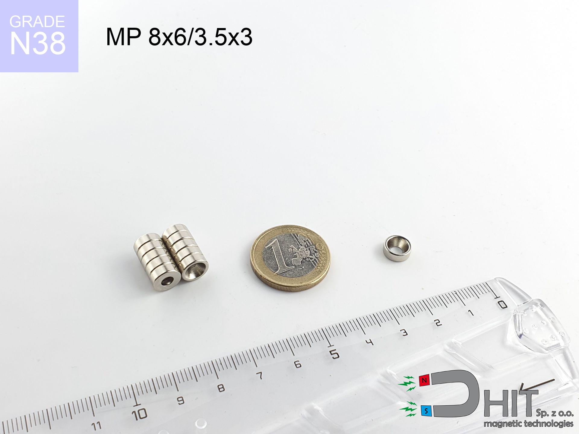
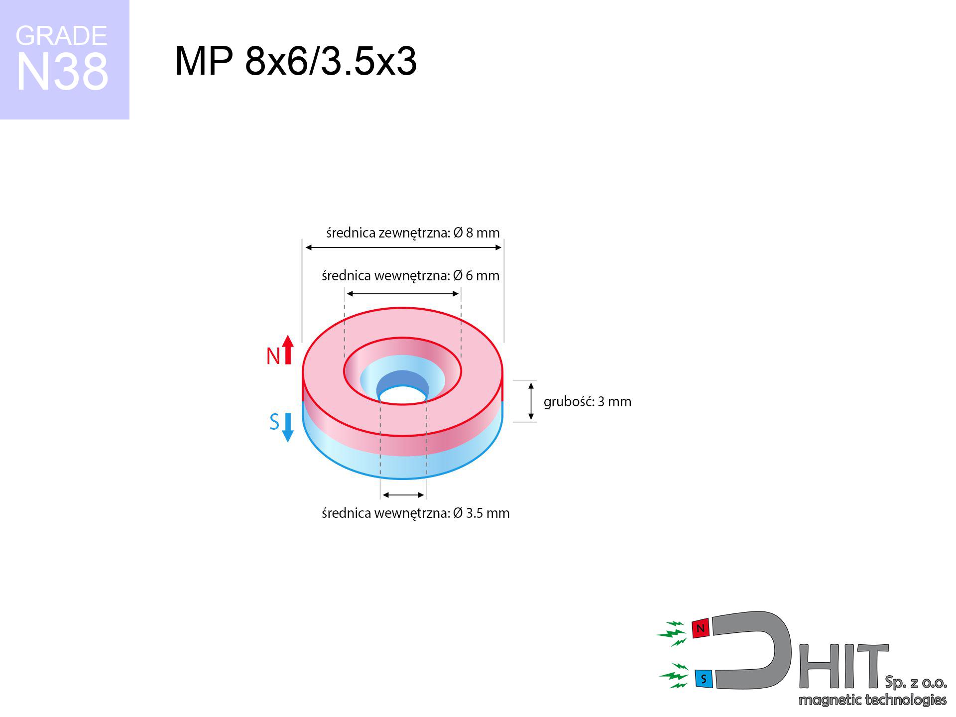
MP 8x6/3.5x3 / N38 - ring magnet
ring magnet
Catalog no 030206
GTIN/EAN: 5906301812234
Diameter
8 mm [±0,1 mm]
internal diameter Ø
6/3.5 mm [±0,1 mm]
Height
3 mm [±0,1 mm]
Weight
0.91 g
Magnetization Direction
↑ axial
Load capacity
1.37 kg / 13.48 N
Magnetic Induction
371.53 mT / 3715 Gs
Coating
[NiCuNi] Nickel
0.701 ZŁ with VAT / pcs + price for transport
0.570 ZŁ net + 23% VAT / pcs
bulk discounts:
Need more?
Pick up the phone and ask
+48 22 499 98 98
or let us know using
contact form
our website.
Force along with structure of magnetic components can be calculated with our
force calculator.
Order by 14:00 and we’ll ship today!
Detailed specification - MP 8x6/3.5x3 / N38 - ring magnet
Specification / characteristics - MP 8x6/3.5x3 / N38 - ring magnet
| properties | values |
|---|---|
| Cat. no. | 030206 |
| GTIN/EAN | 5906301812234 |
| Production/Distribution | Dhit sp. z o.o. |
| Country of origin | Poland / China / Germany |
| Customs code | 85059029 |
| Diameter | 8 mm [±0,1 mm] |
| internal diameter Ø | 6/3.5 mm [±0,1 mm] |
| Height | 3 mm [±0,1 mm] |
| Weight | 0.91 g |
| Magnetization Direction | ↑ axial |
| Load capacity ~ ? | 1.37 kg / 13.48 N |
| Magnetic Induction ~ ? | 371.53 mT / 3715 Gs |
| Coating | [NiCuNi] Nickel |
| Manufacturing Tolerance | ±0.1 mm |
Magnetic properties of material N38
| properties | values | units |
|---|---|---|
| remenance Br [min. - max.] ? | 12.2-12.6 | kGs |
| remenance Br [min. - max.] ? | 1220-1260 | mT |
| coercivity bHc ? | 10.8-11.5 | kOe |
| coercivity bHc ? | 860-915 | kA/m |
| actual internal force iHc | ≥ 12 | kOe |
| actual internal force iHc | ≥ 955 | kA/m |
| energy density [min. - max.] ? | 36-38 | BH max MGOe |
| energy density [min. - max.] ? | 287-303 | BH max KJ/m |
| max. temperature ? | ≤ 80 | °C |
Physical properties of sintered neodymium magnets Nd2Fe14B at 20°C
| properties | values | units |
|---|---|---|
| Vickers hardness | ≥550 | Hv |
| Density | ≥7.4 | g/cm3 |
| Curie Temperature TC | 312 - 380 | °C |
| Curie Temperature TF | 593 - 716 | °F |
| Specific resistance | 150 | μΩ⋅cm |
| Bending strength | 250 | MPa |
| Compressive strength | 1000~1100 | MPa |
| Thermal expansion parallel (∥) to orientation (M) | (3-4) x 10-6 | °C-1 |
| Thermal expansion perpendicular (⊥) to orientation (M) | -(1-3) x 10-6 | °C-1 |
| Young's modulus | 1.7 x 10⁴ | kg/mm² |
Technical analysis of the product - data
Presented data are the direct effect of a engineering simulation. Results are based on algorithms for the material Nd2Fe14B. Real-world performance may deviate from the simulation results. Please consider these data as a supplementary guide during assembly planning.
Table 1: Static pull force (force vs gap) - characteristics
MP 8x6/3.5x3 / N38
| Distance (mm) | Induction (Gauss) / mT | Pull Force (kg/lbs/g/N) | Risk Status |
|---|---|---|---|
| 0 mm |
3327 Gs
332.7 mT
|
1.37 kg / 3.02 pounds
1370.0 g / 13.4 N
|
low risk |
| 1 mm |
2612 Gs
261.2 mT
|
0.84 kg / 1.86 pounds
844.4 g / 8.3 N
|
low risk |
| 2 mm |
1884 Gs
188.4 mT
|
0.44 kg / 0.97 pounds
439.3 g / 4.3 N
|
low risk |
| 3 mm |
1310 Gs
131.0 mT
|
0.21 kg / 0.47 pounds
212.4 g / 2.1 N
|
low risk |
| 5 mm |
637 Gs
63.7 mT
|
0.05 kg / 0.11 pounds
50.3 g / 0.5 N
|
low risk |
| 10 mm |
151 Gs
15.1 mT
|
0.00 kg / 0.01 pounds
2.8 g / 0.0 N
|
low risk |
| 15 mm |
54 Gs
5.4 mT
|
0.00 kg / 0.00 pounds
0.4 g / 0.0 N
|
low risk |
| 20 mm |
25 Gs
2.5 mT
|
0.00 kg / 0.00 pounds
0.1 g / 0.0 N
|
low risk |
| 30 mm |
8 Gs
0.8 mT
|
0.00 kg / 0.00 pounds
0.0 g / 0.0 N
|
low risk |
| 50 mm |
2 Gs
0.2 mT
|
0.00 kg / 0.00 pounds
0.0 g / 0.0 N
|
low risk |
Table 2: Slippage hold (wall)
MP 8x6/3.5x3 / N38
| Distance (mm) | Friction coefficient | Pull Force (kg/lbs/g/N) |
|---|---|---|
| 0 mm | Stal (~0.2) |
0.27 kg / 0.60 pounds
274.0 g / 2.7 N
|
| 1 mm | Stal (~0.2) |
0.17 kg / 0.37 pounds
168.0 g / 1.6 N
|
| 2 mm | Stal (~0.2) |
0.09 kg / 0.19 pounds
88.0 g / 0.9 N
|
| 3 mm | Stal (~0.2) |
0.04 kg / 0.09 pounds
42.0 g / 0.4 N
|
| 5 mm | Stal (~0.2) |
0.01 kg / 0.02 pounds
10.0 g / 0.1 N
|
| 10 mm | Stal (~0.2) |
0.00 kg / 0.00 pounds
0.0 g / 0.0 N
|
| 15 mm | Stal (~0.2) |
0.00 kg / 0.00 pounds
0.0 g / 0.0 N
|
| 20 mm | Stal (~0.2) |
0.00 kg / 0.00 pounds
0.0 g / 0.0 N
|
| 30 mm | Stal (~0.2) |
0.00 kg / 0.00 pounds
0.0 g / 0.0 N
|
| 50 mm | Stal (~0.2) |
0.00 kg / 0.00 pounds
0.0 g / 0.0 N
|
Table 3: Wall mounting (sliding) - behavior on slippery surfaces
MP 8x6/3.5x3 / N38
| Surface type | Friction coefficient / % Mocy | Max load (kg/lbs/g/N) |
|---|---|---|
| Raw steel |
µ = 0.3
30% Nominalnej Siły
|
0.41 kg / 0.91 pounds
411.0 g / 4.0 N
|
| Painted steel (standard) |
µ = 0.2
20% Nominalnej Siły
|
0.27 kg / 0.60 pounds
274.0 g / 2.7 N
|
| Oily/slippery steel |
µ = 0.1
10% Nominalnej Siły
|
0.14 kg / 0.30 pounds
137.0 g / 1.3 N
|
| Magnet with anti-slip rubber |
µ = 0.5
50% Nominalnej Siły
|
0.69 kg / 1.51 pounds
685.0 g / 6.7 N
|
Table 4: Material efficiency (saturation) - power losses
MP 8x6/3.5x3 / N38
| Steel thickness (mm) | % power | Real pull force (kg/lbs/g/N) |
|---|---|---|
| 0.5 mm |
|
0.14 kg / 0.30 pounds
137.0 g / 1.3 N
|
| 1 mm |
|
0.34 kg / 0.76 pounds
342.5 g / 3.4 N
|
| 2 mm |
|
0.69 kg / 1.51 pounds
685.0 g / 6.7 N
|
| 3 mm |
|
1.03 kg / 2.27 pounds
1027.5 g / 10.1 N
|
| 5 mm |
|
1.37 kg / 3.02 pounds
1370.0 g / 13.4 N
|
| 10 mm |
|
1.37 kg / 3.02 pounds
1370.0 g / 13.4 N
|
| 11 mm |
|
1.37 kg / 3.02 pounds
1370.0 g / 13.4 N
|
| 12 mm |
|
1.37 kg / 3.02 pounds
1370.0 g / 13.4 N
|
Table 5: Working in heat (material behavior) - power drop
MP 8x6/3.5x3 / N38
| Ambient temp. (°C) | Power loss | Remaining pull (kg/lbs/g/N) | Status |
|---|---|---|---|
| 20 °C | 0.0% |
1.37 kg / 3.02 pounds
1370.0 g / 13.4 N
|
OK |
| 40 °C | -2.2% |
1.34 kg / 2.95 pounds
1339.9 g / 13.1 N
|
OK |
| 60 °C | -4.4% |
1.31 kg / 2.89 pounds
1309.7 g / 12.8 N
|
|
| 80 °C | -6.6% |
1.28 kg / 2.82 pounds
1279.6 g / 12.6 N
|
|
| 100 °C | -28.8% |
0.98 kg / 2.15 pounds
975.4 g / 9.6 N
|
Table 6: Two magnets (repulsion) - field collision
MP 8x6/3.5x3 / N38
| Gap (mm) | Attraction (kg/lbs) (N-S) | Shear Force (kg/lbs/g/N) | Repulsion (kg/lbs) (N-N) |
|---|---|---|---|
| 0 mm |
2.36 kg / 5.20 pounds
4 867 Gs
|
0.35 kg / 0.78 pounds
354 g / 3.5 N
|
N/A |
| 1 mm |
1.90 kg / 4.20 pounds
5 981 Gs
|
0.29 kg / 0.63 pounds
286 g / 2.8 N
|
1.71 kg / 3.78 pounds
~0 Gs
|
| 2 mm |
1.45 kg / 3.20 pounds
5 223 Gs
|
0.22 kg / 0.48 pounds
218 g / 2.1 N
|
1.31 kg / 2.88 pounds
~0 Gs
|
| 3 mm |
1.06 kg / 2.34 pounds
4 468 Gs
|
0.16 kg / 0.35 pounds
159 g / 1.6 N
|
0.96 kg / 2.11 pounds
~0 Gs
|
| 5 mm |
0.53 kg / 1.16 pounds
3 148 Gs
|
0.08 kg / 0.17 pounds
79 g / 0.8 N
|
0.47 kg / 1.05 pounds
~0 Gs
|
| 10 mm |
0.09 kg / 0.19 pounds
1 274 Gs
|
0.01 kg / 0.03 pounds
13 g / 0.1 N
|
0.08 kg / 0.17 pounds
~0 Gs
|
| 20 mm |
0.00 kg / 0.01 pounds
301 Gs
|
0.00 kg / 0.00 pounds
1 g / 0.0 N
|
0.00 kg / 0.00 pounds
~0 Gs
|
| 50 mm |
0.00 kg / 0.00 pounds
27 Gs
|
0.00 kg / 0.00 pounds
0 g / 0.0 N
|
0.00 kg / 0.00 pounds
~0 Gs
|
| 60 mm |
0.00 kg / 0.00 pounds
16 Gs
|
0.00 kg / 0.00 pounds
0 g / 0.0 N
|
0.00 kg / 0.00 pounds
~0 Gs
|
| 70 mm |
0.00 kg / 0.00 pounds
10 Gs
|
0.00 kg / 0.00 pounds
0 g / 0.0 N
|
0.00 kg / 0.00 pounds
~0 Gs
|
| 80 mm |
0.00 kg / 0.00 pounds
7 Gs
|
0.00 kg / 0.00 pounds
0 g / 0.0 N
|
0.00 kg / 0.00 pounds
~0 Gs
|
| 90 mm |
0.00 kg / 0.00 pounds
5 Gs
|
0.00 kg / 0.00 pounds
0 g / 0.0 N
|
0.00 kg / 0.00 pounds
~0 Gs
|
| 100 mm |
0.00 kg / 0.00 pounds
4 Gs
|
0.00 kg / 0.00 pounds
0 g / 0.0 N
|
0.00 kg / 0.00 pounds
~0 Gs
|
Table 7: Protective zones (implants) - precautionary measures
MP 8x6/3.5x3 / N38
| Object / Device | Limit (Gauss) / mT | Safe distance |
|---|---|---|
| Pacemaker | 5 Gs (0.5 mT) | 4.0 cm |
| Hearing aid | 10 Gs (1.0 mT) | 3.0 cm |
| Mechanical watch | 20 Gs (2.0 mT) | 2.5 cm |
| Mobile device | 40 Gs (4.0 mT) | 2.0 cm |
| Car key | 50 Gs (5.0 mT) | 2.0 cm |
| Payment card | 400 Gs (40.0 mT) | 1.0 cm |
| HDD hard drive | 600 Gs (60.0 mT) | 1.0 cm |
Table 8: Collisions (cracking risk) - collision effects
MP 8x6/3.5x3 / N38
| Start from (mm) | Speed (km/h) | Energy (J) | Predicted outcome |
|---|---|---|---|
| 10 mm |
39.18 km/h
(10.88 m/s)
|
0.05 J | |
| 30 mm |
67.78 km/h
(18.83 m/s)
|
0.16 J | |
| 50 mm |
87.50 km/h
(24.31 m/s)
|
0.27 J | |
| 100 mm |
123.74 km/h
(34.37 m/s)
|
0.54 J |
Table 9: Corrosion resistance
MP 8x6/3.5x3 / N38
| Technical parameter | Value / Description |
|---|---|
| Coating type | [NiCuNi] Nickel |
| Layer structure | Nickel - Copper - Nickel |
| Layer thickness | 10-20 µm |
| Salt spray test (SST) ? | 24 h |
| Recommended environment | Indoors only (dry) |
Table 10: Electrical data (Flux)
MP 8x6/3.5x3 / N38
| Parameter | Value | SI Unit / Description |
|---|---|---|
| Magnetic Flux | 1 299 Mx | 13.0 µWb |
| Pc Coefficient | 0.46 | Low (Flat) |
Table 11: Hydrostatics and buoyancy
MP 8x6/3.5x3 / N38
| Environment | Effective steel pull | Effect |
|---|---|---|
| Air (land) | 1.37 kg | Standard |
| Water (riverbed) |
1.57 kg
(+0.20 kg buoyancy gain)
|
+14.5% |
1. Vertical hold
*Warning: On a vertical wall, the magnet retains just ~20% of its max power.
2. Steel thickness impact
*Thin steel (e.g. computer case) significantly limits the holding force.
3. Heat tolerance
*For standard magnets, the max working temp is 80°C.
4. Demagnetization curve and operating point (B-H)
chart generated for the permeance coefficient Pc (Permeance Coefficient) = 0.46
The chart above illustrates the magnetic characteristics of the material within the second quadrant of the hysteresis loop. The solid red line represents the demagnetization curve (material potential), while the dashed blue line is the load line based on the magnet's geometry. The Pc (Permeance Coefficient), also known as the load line slope, is a dimensionless value that describes the relationship between the magnet's shape and its magnetic stability. The intersection of these two lines (the black dot) is the operating point — it determines the actual magnetic flux density generated by the magnet in this specific configuration. A higher Pc value means the magnet is more 'slender' (tall relative to its area), resulting in a higher operating point and better resistance to irreversible demagnetization caused by external fields or temperature. A value of 0.42 is relatively low (typical for flat magnets), meaning the operating point is closer to the 'knee' of the curve — caution is advised when operating at temperatures near the maximum limit to avoid strength loss.
Elemental analysis
| iron (Fe) | 64% – 68% |
| neodymium (Nd) | 29% – 32% |
| boron (B) | 1.1% – 1.2% |
| dysprosium (Dy) | 0.5% – 2.0% |
| coating (Ni-Cu-Ni) | < 0.05% |
Ecology and recycling (GPSR)
| recyclability (EoL) | 100% |
| recycled raw materials | ~10% (pre-cons) |
| carbon footprint | low / zredukowany |
| waste code (EWC) | 16 02 16 |
Other offers

![SM 25x100 [2xM8] / N52 - magnetic separator](https://cdn3.dhit.pl/graphics/products/sm-25x100-2xm8-fin.jpg "SM 25x100 [2xM8] / N52 - magnetic separator")

![UI 45x13x6 [C321] / N38 - badge holder](https://cdn3.dhit.pl/graphics/products/ui45x13x6-c321-jic.jpg "UI 45x13x6 [C321] / N38 - badge holder")
Pros and cons of neodymium magnets.
Pros
- They do not lose power, even during around 10 years – the reduction in power is only ~1% (theoretically),
- Neodymium magnets are characterized by highly resistant to demagnetization caused by external interference,
- By applying a shiny layer of nickel, the element acquires an aesthetic look,
- Neodymium magnets deliver maximum magnetic induction on a small surface, which allows for strong attraction,
- Neodymium magnets are characterized by very high magnetic induction on the magnet surface and can work (depending on the shape) even at a temperature of 230°C or more...
- Thanks to modularity in constructing and the capacity to modify to individual projects,
- Huge importance in high-tech industry – they are utilized in data components, motor assemblies, advanced medical instruments, and modern systems.
- Relatively small size with high pulling force – neodymium magnets offer strong magnetic field in tiny dimensions, which makes them useful in compact constructions
Weaknesses
- To avoid cracks under impact, we suggest using special steel housings. Such a solution protects the magnet and simultaneously increases its durability.
- Neodymium magnets lose their force under the influence of heating. As soon as 80°C is exceeded, many of them start losing their force. Therefore, we recommend our special magnets marked [AH], which maintain durability even at temperatures up to 230°C
- Magnets exposed to a humid environment can corrode. Therefore during using outdoors, we suggest using water-impermeable magnets made of rubber, plastic or other material resistant to moisture
- Due to limitations in producing threads and complex shapes in magnets, we propose using casing - magnetic mount.
- Potential hazard resulting from small fragments of magnets are risky, in case of ingestion, which gains importance in the aspect of protecting the youngest. Additionally, tiny parts of these magnets are able to be problematic in diagnostics medical when they are in the body.
- Due to neodymium price, their price is higher than average,
Lifting parameters
Detachment force of the magnet in optimal conditions – what it depends on?
- on a base made of structural steel, perfectly concentrating the magnetic flux
- with a thickness no less than 10 mm
- characterized by smoothness
- without any clearance between the magnet and steel
- under vertical force direction (90-degree angle)
- in temp. approx. 20°C
Lifting capacity in real conditions – factors
- Clearance – existence of any layer (paint, dirt, gap) acts as an insulator, which lowers power steeply (even by 50% at 0.5 mm).
- Loading method – declared lifting capacity refers to detachment vertically. When applying parallel force, the magnet holds much less (often approx. 20-30% of maximum force).
- Steel thickness – too thin sheet does not accept the full field, causing part of the flux to be escaped to the other side.
- Steel type – mild steel gives the best results. Higher carbon content decrease magnetic properties and lifting capacity.
- Base smoothness – the smoother and more polished the plate, the better the adhesion and higher the lifting capacity. Unevenness acts like micro-gaps.
- Thermal factor – high temperature reduces magnetic field. Too high temperature can permanently damage the magnet.
Lifting capacity was assessed using a polished steel plate of optimal thickness (min. 20 mm), under vertically applied force, in contrast under parallel forces the holding force is lower. Moreover, even a small distance between the magnet’s surface and the plate lowers the holding force.
Safe handling of neodymium magnets
Electronic devices
Do not bring magnets close to a wallet, computer, or screen. The magnetic field can destroy these devices and erase data from cards.
Avoid contact if allergic
Medical facts indicate that the nickel plating (standard magnet coating) is a potent allergen. For allergy sufferers, prevent direct skin contact or select coated magnets.
No play value
Product intended for adults. Tiny parts pose a choking risk, leading to intestinal necrosis. Keep out of reach of children and animals.
Operating temperature
Control the heat. Exposing the magnet to high heat will ruin its properties and pulling force.
Safe operation
Before starting, read the rules. Sudden snapping can destroy the magnet or hurt your hand. Think ahead.
GPS and phone interference
GPS units and smartphones are highly susceptible to magnetism. Close proximity with a strong magnet can permanently damage the internal compass in your phone.
Dust explosion hazard
Machining of neodymium magnets carries a risk of fire risk. Magnetic powder oxidizes rapidly with oxygen and is hard to extinguish.
Magnets are brittle
Despite the nickel coating, neodymium is brittle and cannot withstand shocks. Do not hit, as the magnet may shatter into hazardous fragments.
Warning for heart patients
For implant holders: Strong magnetic fields disrupt medical devices. Maintain at least 30 cm distance or ask another person to work with the magnets.
Hand protection
Large magnets can crush fingers instantly. Do not place your hand between two strong magnets.
Tabela kosztu i czasu dostawy
Płatność przed wysyłką:

GLS kurier
Przesyłka będzie u Ciebie za 2-3 dni
14.99 ZŁ

InPost Paczkomaty 24/7
Przesyłka będzie u Ciebie za 1-2 dni
12.30 ZŁ
Płatność przy odbiorze (pobranie):
GLS kurier
Przesyłka będzie u Ciebie za 1-2 dni
23.00 ZŁ
Rate the product
Your rating