
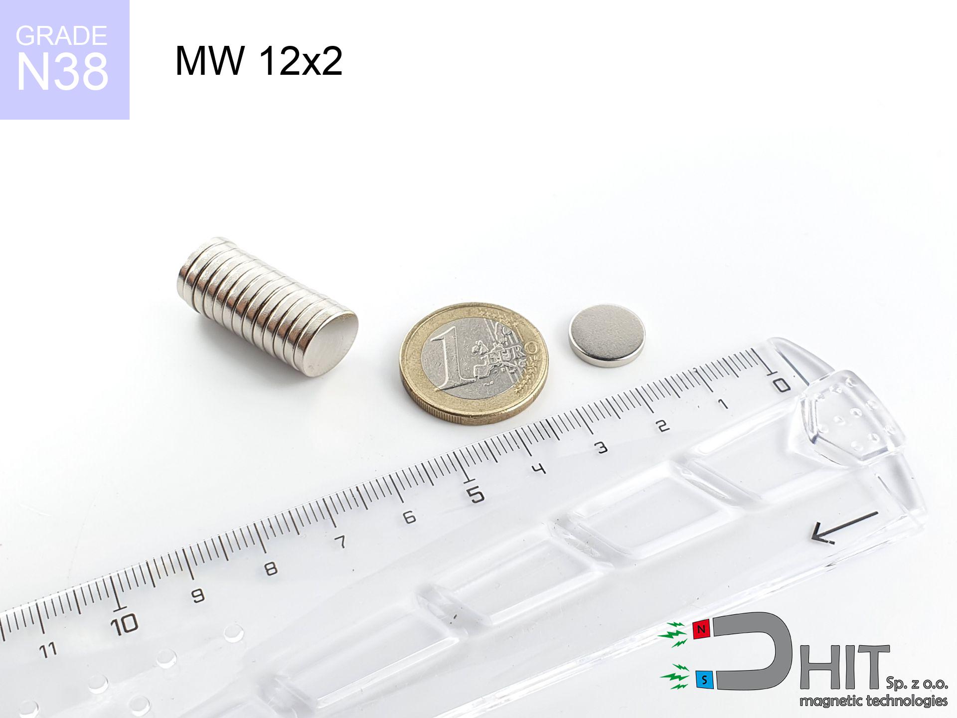
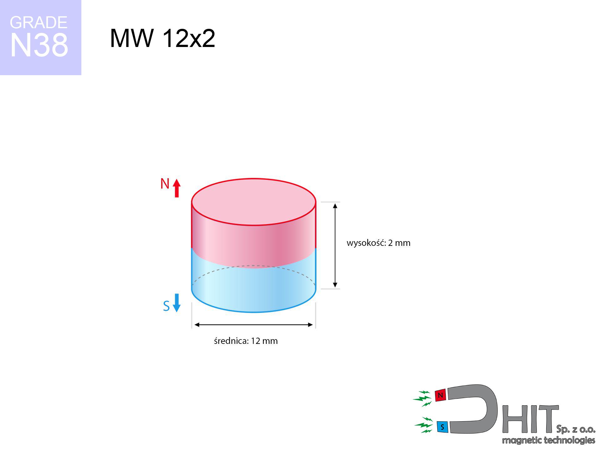
MW 12x2 / N38 - cylindrical magnet
cylindrical magnet
Catalog no 010017
GTIN/EAN: 5906301810162
Diameter Ø
12 mm [±0,1 mm]
Height
2 mm [±0,1 mm]
Weight
1.7 g
Magnetization Direction
↑ axial
Load capacity
1.39 kg / 13.66 N
Magnetic Induction
195.97 mT / 1960 Gs
Coating
[NiCuNi] Nickel
1.132 ZŁ with VAT / pcs + price for transport
0.920 ZŁ net + 23% VAT / pcs
bulk discounts:
Need more?
Give us a call
+48 22 499 98 98
if you prefer drop us a message via
inquiry form
through our site.
Specifications along with form of a neodymium magnet can be reviewed with our
magnetic mass calculator.
Same-day processing for orders placed before 14:00.
Technical of the product - MW 12x2 / N38 - cylindrical magnet
Specification / characteristics - MW 12x2 / N38 - cylindrical magnet
| properties | values |
|---|---|
| Cat. no. | 010017 |
| GTIN/EAN | 5906301810162 |
| Production/Distribution | Dhit sp. z o.o. |
| Country of origin | Poland / China / Germany |
| Customs code | 85059029 |
| Diameter Ø | 12 mm [±0,1 mm] |
| Height | 2 mm [±0,1 mm] |
| Weight | 1.7 g |
| Magnetization Direction | ↑ axial |
| Load capacity ~ ? | 1.39 kg / 13.66 N |
| Magnetic Induction ~ ? | 195.97 mT / 1960 Gs |
| Coating | [NiCuNi] Nickel |
| Manufacturing Tolerance | ±0.1 mm |
Magnetic properties of material N38
| properties | values | units |
|---|---|---|
| remenance Br [min. - max.] ? | 12.2-12.6 | kGs |
| remenance Br [min. - max.] ? | 1220-1260 | mT |
| coercivity bHc ? | 10.8-11.5 | kOe |
| coercivity bHc ? | 860-915 | kA/m |
| actual internal force iHc | ≥ 12 | kOe |
| actual internal force iHc | ≥ 955 | kA/m |
| energy density [min. - max.] ? | 36-38 | BH max MGOe |
| energy density [min. - max.] ? | 287-303 | BH max KJ/m |
| max. temperature ? | ≤ 80 | °C |
Physical properties of sintered neodymium magnets Nd2Fe14B at 20°C
| properties | values | units |
|---|---|---|
| Vickers hardness | ≥550 | Hv |
| Density | ≥7.4 | g/cm3 |
| Curie Temperature TC | 312 - 380 | °C |
| Curie Temperature TF | 593 - 716 | °F |
| Specific resistance | 150 | μΩ⋅cm |
| Bending strength | 250 | MPa |
| Compressive strength | 1000~1100 | MPa |
| Thermal expansion parallel (∥) to orientation (M) | (3-4) x 10-6 | °C-1 |
| Thermal expansion perpendicular (⊥) to orientation (M) | -(1-3) x 10-6 | °C-1 |
| Young's modulus | 1.7 x 10⁴ | kg/mm² |
Physical simulation of the product - technical parameters
These information constitute the result of a physical simulation. Results are based on models for the material Nd2Fe14B. Real-world performance may deviate from the simulation results. Use these calculations as a preliminary roadmap for designers.
Table 1: Static force (force vs distance) - interaction chart
MW 12x2 / N38
| Distance (mm) | Induction (Gauss) / mT | Pull Force (kg/lbs/g/N) | Risk Status |
|---|---|---|---|
| 0 mm |
1959 Gs
195.9 mT
|
1.39 kg / 3.06 lbs
1390.0 g / 13.6 N
|
safe |
| 1 mm |
1753 Gs
175.3 mT
|
1.11 kg / 2.45 lbs
1113.5 g / 10.9 N
|
safe |
| 2 mm |
1479 Gs
147.9 mT
|
0.79 kg / 1.75 lbs
791.7 g / 7.8 N
|
safe |
| 3 mm |
1196 Gs
119.6 mT
|
0.52 kg / 1.14 lbs
518.4 g / 5.1 N
|
safe |
| 5 mm |
738 Gs
73.8 mT
|
0.20 kg / 0.44 lbs
197.4 g / 1.9 N
|
safe |
| 10 mm |
229 Gs
22.9 mT
|
0.02 kg / 0.04 lbs
19.0 g / 0.2 N
|
safe |
| 15 mm |
90 Gs
9.0 mT
|
0.00 kg / 0.01 lbs
2.9 g / 0.0 N
|
safe |
| 20 mm |
43 Gs
4.3 mT
|
0.00 kg / 0.00 lbs
0.7 g / 0.0 N
|
safe |
| 30 mm |
14 Gs
1.4 mT
|
0.00 kg / 0.00 lbs
0.1 g / 0.0 N
|
safe |
| 50 mm |
3 Gs
0.3 mT
|
0.00 kg / 0.00 lbs
0.0 g / 0.0 N
|
safe |
Table 2: Shear force (vertical surface)
MW 12x2 / N38
| Distance (mm) | Friction coefficient | Pull Force (kg/lbs/g/N) |
|---|---|---|
| 0 mm | Stal (~0.2) |
0.28 kg / 0.61 lbs
278.0 g / 2.7 N
|
| 1 mm | Stal (~0.2) |
0.22 kg / 0.49 lbs
222.0 g / 2.2 N
|
| 2 mm | Stal (~0.2) |
0.16 kg / 0.35 lbs
158.0 g / 1.5 N
|
| 3 mm | Stal (~0.2) |
0.10 kg / 0.23 lbs
104.0 g / 1.0 N
|
| 5 mm | Stal (~0.2) |
0.04 kg / 0.09 lbs
40.0 g / 0.4 N
|
| 10 mm | Stal (~0.2) |
0.00 kg / 0.01 lbs
4.0 g / 0.0 N
|
| 15 mm | Stal (~0.2) |
0.00 kg / 0.00 lbs
0.0 g / 0.0 N
|
| 20 mm | Stal (~0.2) |
0.00 kg / 0.00 lbs
0.0 g / 0.0 N
|
| 30 mm | Stal (~0.2) |
0.00 kg / 0.00 lbs
0.0 g / 0.0 N
|
| 50 mm | Stal (~0.2) |
0.00 kg / 0.00 lbs
0.0 g / 0.0 N
|
Table 3: Vertical assembly (shearing) - behavior on slippery surfaces
MW 12x2 / N38
| Surface type | Friction coefficient / % Mocy | Max load (kg/lbs/g/N) |
|---|---|---|
| Raw steel |
µ = 0.3
30% Nominalnej Siły
|
0.42 kg / 0.92 lbs
417.0 g / 4.1 N
|
| Painted steel (standard) |
µ = 0.2
20% Nominalnej Siły
|
0.28 kg / 0.61 lbs
278.0 g / 2.7 N
|
| Oily/slippery steel |
µ = 0.1
10% Nominalnej Siły
|
0.14 kg / 0.31 lbs
139.0 g / 1.4 N
|
| Magnet with anti-slip rubber |
µ = 0.5
50% Nominalnej Siły
|
0.70 kg / 1.53 lbs
695.0 g / 6.8 N
|
Table 4: Steel thickness (substrate influence) - sheet metal selection
MW 12x2 / N38
| Steel thickness (mm) | % power | Real pull force (kg/lbs/g/N) |
|---|---|---|
| 0.5 mm |
|
0.14 kg / 0.31 lbs
139.0 g / 1.4 N
|
| 1 mm |
|
0.35 kg / 0.77 lbs
347.5 g / 3.4 N
|
| 2 mm |
|
0.70 kg / 1.53 lbs
695.0 g / 6.8 N
|
| 3 mm |
|
1.04 kg / 2.30 lbs
1042.5 g / 10.2 N
|
| 5 mm |
|
1.39 kg / 3.06 lbs
1390.0 g / 13.6 N
|
| 10 mm |
|
1.39 kg / 3.06 lbs
1390.0 g / 13.6 N
|
| 11 mm |
|
1.39 kg / 3.06 lbs
1390.0 g / 13.6 N
|
| 12 mm |
|
1.39 kg / 3.06 lbs
1390.0 g / 13.6 N
|
Table 5: Thermal resistance (stability) - thermal limit
MW 12x2 / N38
| Ambient temp. (°C) | Power loss | Remaining pull (kg/lbs/g/N) | Status |
|---|---|---|---|
| 20 °C | 0.0% |
1.39 kg / 3.06 lbs
1390.0 g / 13.6 N
|
OK |
| 40 °C | -2.2% |
1.36 kg / 3.00 lbs
1359.4 g / 13.3 N
|
OK |
| 60 °C | -4.4% |
1.33 kg / 2.93 lbs
1328.8 g / 13.0 N
|
|
| 80 °C | -6.6% |
1.30 kg / 2.86 lbs
1298.3 g / 12.7 N
|
|
| 100 °C | -28.8% |
0.99 kg / 2.18 lbs
989.7 g / 9.7 N
|
Table 6: Magnet-Magnet interaction (repulsion) - field range
MW 12x2 / N38
| Gap (mm) | Attraction (kg/lbs) (N-S) | Shear Force (kg/lbs/g/N) | Repulsion (kg/lbs) (N-N) |
|---|---|---|---|
| 0 mm |
2.68 kg / 5.90 lbs
3 435 Gs
|
0.40 kg / 0.88 lbs
401 g / 3.9 N
|
N/A |
| 1 mm |
2.44 kg / 5.37 lbs
3 739 Gs
|
0.37 kg / 0.81 lbs
366 g / 3.6 N
|
2.19 kg / 4.84 lbs
~0 Gs
|
| 2 mm |
2.14 kg / 4.73 lbs
3 507 Gs
|
0.32 kg / 0.71 lbs
322 g / 3.2 N
|
1.93 kg / 4.25 lbs
~0 Gs
|
| 3 mm |
1.83 kg / 4.04 lbs
3 241 Gs
|
0.27 kg / 0.61 lbs
275 g / 2.7 N
|
1.65 kg / 3.63 lbs
~0 Gs
|
| 5 mm |
1.24 kg / 2.74 lbs
2 671 Gs
|
0.19 kg / 0.41 lbs
187 g / 1.8 N
|
1.12 kg / 2.47 lbs
~0 Gs
|
| 10 mm |
0.38 kg / 0.84 lbs
1 476 Gs
|
0.06 kg / 0.13 lbs
57 g / 0.6 N
|
0.34 kg / 0.75 lbs
~0 Gs
|
| 20 mm |
0.04 kg / 0.08 lbs
458 Gs
|
0.01 kg / 0.01 lbs
5 g / 0.1 N
|
0.03 kg / 0.07 lbs
~0 Gs
|
| 50 mm |
0.00 kg / 0.00 lbs
47 Gs
|
0.00 kg / 0.00 lbs
0 g / 0.0 N
|
0.00 kg / 0.00 lbs
~0 Gs
|
| 60 mm |
0.00 kg / 0.00 lbs
28 Gs
|
0.00 kg / 0.00 lbs
0 g / 0.0 N
|
0.00 kg / 0.00 lbs
~0 Gs
|
| 70 mm |
0.00 kg / 0.00 lbs
18 Gs
|
0.00 kg / 0.00 lbs
0 g / 0.0 N
|
0.00 kg / 0.00 lbs
~0 Gs
|
| 80 mm |
0.00 kg / 0.00 lbs
13 Gs
|
0.00 kg / 0.00 lbs
0 g / 0.0 N
|
0.00 kg / 0.00 lbs
~0 Gs
|
| 90 mm |
0.00 kg / 0.00 lbs
9 Gs
|
0.00 kg / 0.00 lbs
0 g / 0.0 N
|
0.00 kg / 0.00 lbs
~0 Gs
|
| 100 mm |
0.00 kg / 0.00 lbs
7 Gs
|
0.00 kg / 0.00 lbs
0 g / 0.0 N
|
0.00 kg / 0.00 lbs
~0 Gs
|
Table 7: Hazards (electronics) - warnings
MW 12x2 / N38
| Object / Device | Limit (Gauss) / mT | Safe distance |
|---|---|---|
| Pacemaker | 5 Gs (0.5 mT) | 4.5 cm |
| Hearing aid | 10 Gs (1.0 mT) | 3.5 cm |
| Mechanical watch | 20 Gs (2.0 mT) | 3.0 cm |
| Mobile device | 40 Gs (4.0 mT) | 2.5 cm |
| Remote | 50 Gs (5.0 mT) | 2.0 cm |
| Payment card | 400 Gs (40.0 mT) | 1.0 cm |
| HDD hard drive | 600 Gs (60.0 mT) | 1.0 cm |
Table 8: Impact energy (kinetic energy) - collision effects
MW 12x2 / N38
| Start from (mm) | Speed (km/h) | Energy (J) | Predicted outcome |
|---|---|---|---|
| 10 mm |
29.08 km/h
(8.08 m/s)
|
0.06 J | |
| 30 mm |
49.95 km/h
(13.88 m/s)
|
0.16 J | |
| 50 mm |
64.48 km/h
(17.91 m/s)
|
0.27 J | |
| 100 mm |
91.19 km/h
(25.33 m/s)
|
0.55 J |
Table 9: Anti-corrosion coating durability
MW 12x2 / N38
| Technical parameter | Value / Description |
|---|---|
| Coating type | [NiCuNi] Nickel |
| Layer structure | Nickel - Copper - Nickel |
| Layer thickness | 10-20 µm |
| Salt spray test (SST) ? | 24 h |
| Recommended environment | Indoors only (dry) |
Table 10: Construction data (Pc)
MW 12x2 / N38
| Parameter | Value | SI Unit / Description |
|---|---|---|
| Magnetic Flux | 2 665 Mx | 26.7 µWb |
| Pc Coefficient | 0.25 | Low (Flat) |
Table 11: Hydrostatics and buoyancy
MW 12x2 / N38
| Environment | Effective steel pull | Effect |
|---|---|---|
| Air (land) | 1.39 kg | Standard |
| Water (riverbed) |
1.59 kg
(+0.20 kg buoyancy gain)
|
+14.5% |
1. Vertical hold
*Caution: On a vertical wall, the magnet retains just approx. 20-30% of its max power.
2. Steel thickness impact
*Thin steel (e.g. computer case) significantly weakens the holding force.
3. Heat tolerance
*For standard magnets, the safety limit is 80°C.
4. Demagnetization curve and operating point (B-H)
chart generated for the permeance coefficient Pc (Permeance Coefficient) = 0.25
This simulation demonstrates the magnetic stability of the selected magnet under specific geometric conditions. The solid red line represents the demagnetization curve (material potential), while the dashed blue line is the load line based on the magnet's geometry. The Pc (Permeance Coefficient), also known as the load line slope, is a dimensionless value that describes the relationship between the magnet's shape and its magnetic stability. The intersection of these two lines (the black dot) is the operating point — it determines the actual magnetic flux density generated by the magnet in this specific configuration. A higher Pc value means the magnet is more 'slender' (tall relative to its area), resulting in a higher operating point and better resistance to irreversible demagnetization caused by external fields or temperature. A value of 0.42 is relatively low (typical for flat magnets), meaning the operating point is closer to the 'knee' of the curve — caution is advised when operating at temperatures near the maximum limit to avoid strength loss.
Elemental analysis
| iron (Fe) | 64% – 68% |
| neodymium (Nd) | 29% – 32% |
| boron (B) | 1.1% – 1.2% |
| dysprosium (Dy) | 0.5% – 2.0% |
| coating (Ni-Cu-Ni) | < 0.05% |
Sustainability
| recyclability (EoL) | 100% |
| recycled raw materials | ~10% (pre-cons) |
| carbon footprint | low / zredukowany |
| waste code (EWC) | 16 02 16 |
Other proposals


![SM 25x125 [2xM8] / N42 - magnetic separator](https://cdn3.dhit.pl/graphics/products/sm-25x125-2xm8-duj.jpg "SM 25x125 [2xM8] / N42 - magnetic separator")
Strengths and weaknesses of Nd2Fe14B magnets.
Advantages
- They virtually do not lose power, because even after 10 years the performance loss is only ~1% (based on calculations),
- Neodymium magnets are characterized by exceptionally resistant to loss of magnetic properties caused by external magnetic fields,
- Thanks to the glossy finish, the surface of nickel, gold-plated, or silver-plated gives an professional appearance,
- Magnets possess exceptionally strong magnetic induction on the outer layer,
- Due to their durability and thermal resistance, neodymium magnets can operate (depending on the form) even at high temperatures reaching 230°C or more...
- Thanks to versatility in forming and the capacity to adapt to complex applications,
- Key role in advanced technology sectors – they are utilized in HDD drives, electric motors, diagnostic systems, also other advanced devices.
- Compactness – despite small sizes they provide effective action, making them ideal for precision applications
Weaknesses
- They are fragile upon too strong impacts. To avoid cracks, it is worth protecting magnets in a protective case. Such protection not only protects the magnet but also improves its resistance to damage
- We warn that neodymium magnets can reduce their power at high temperatures. To prevent this, we advise our specialized [AH] magnets, which work effectively even at 230°C.
- They oxidize in a humid environment - during use outdoors we advise using waterproof magnets e.g. in rubber, plastic
- We recommend cover - magnetic mount, due to difficulties in producing nuts inside the magnet and complex shapes.
- Possible danger resulting from small fragments of magnets can be dangerous, when accidentally swallowed, which becomes key in the context of child safety. It is also worth noting that small elements of these magnets can be problematic in diagnostics medical when they are in the body.
- Higher cost of purchase is a significant factor to consider compared to ceramic magnets, especially in budget applications
Lifting parameters
Optimal lifting capacity of a neodymium magnet – what it depends on?
- with the contact of a yoke made of special test steel, guaranteeing full magnetic saturation
- whose transverse dimension reaches at least 10 mm
- with an ideally smooth contact surface
- with total lack of distance (without paint)
- for force applied at a right angle (pull-off, not shear)
- at temperature approx. 20 degrees Celsius
Impact of factors on magnetic holding capacity in practice
- Gap (between the magnet and the metal), since even a tiny clearance (e.g. 0.5 mm) leads to a drastic drop in force by up to 50% (this also applies to paint, corrosion or debris).
- Force direction – catalog parameter refers to pulling vertically. When slipping, the magnet holds much less (often approx. 20-30% of maximum force).
- Metal thickness – the thinner the sheet, the weaker the hold. Magnetic flux penetrates through instead of converting into lifting capacity.
- Steel grade – ideal substrate is pure iron steel. Stainless steels may attract less.
- Surface finish – full contact is obtained only on polished steel. Rough texture reduce the real contact area, weakening the magnet.
- Temperature influence – hot environment reduces magnetic field. Too high temperature can permanently damage the magnet.
Lifting capacity testing was carried out on plates with a smooth surface of suitable thickness, under a perpendicular pulling force, whereas under attempts to slide the magnet the load capacity is reduced by as much as 75%. Moreover, even a small distance between the magnet and the plate reduces the load capacity.
Safety rules for work with NdFeB magnets
Mechanical processing
Mechanical processing of neodymium magnets poses a fire hazard. Magnetic powder reacts violently with oxygen and is hard to extinguish.
Beware of splinters
Despite metallic appearance, neodymium is brittle and not impact-resistant. Do not hit, as the magnet may shatter into hazardous fragments.
Serious injuries
Protect your hands. Two large magnets will join immediately with a force of several hundred kilograms, destroying anything in their path. Exercise extreme caution!
GPS Danger
A powerful magnetic field interferes with the functioning of compasses in smartphones and navigation systems. Do not bring magnets near a smartphone to prevent damaging the sensors.
Nickel allergy
Certain individuals suffer from a contact allergy to nickel, which is the typical protective layer for NdFeB magnets. Extended handling may cause an allergic reaction. It is best to wear safety gloves.
Keep away from computers
Data protection: Neodymium magnets can ruin payment cards and delicate electronics (pacemakers, hearing aids, mechanical watches).
Operating temperature
Standard neodymium magnets (N-type) lose power when the temperature goes above 80°C. Damage is permanent.
Handling rules
Use magnets consciously. Their huge power can shock even experienced users. Be vigilant and respect their force.
This is not a toy
Neodymium magnets are not intended for children. Eating several magnets can lead to them connecting inside the digestive tract, which poses a direct threat to life and requires urgent medical intervention.
Danger to pacemakers
For implant holders: Strong magnetic fields affect electronics. Keep at least 30 cm distance or request help to handle the magnets.
Tabela kosztu i czasu dostawy
Płatność przed wysyłką:

GLS kurier
Przesyłka będzie u Ciebie za 2-3 dni
14.99 ZŁ

InPost Paczkomaty 24/7
Przesyłka będzie u Ciebie za 1-2 dni
12.30 ZŁ
Płatność przy odbiorze (pobranie):
GLS kurier
Przesyłka będzie u Ciebie za 1-2 dni
23.00 ZŁ
Rate the product
Your rating