
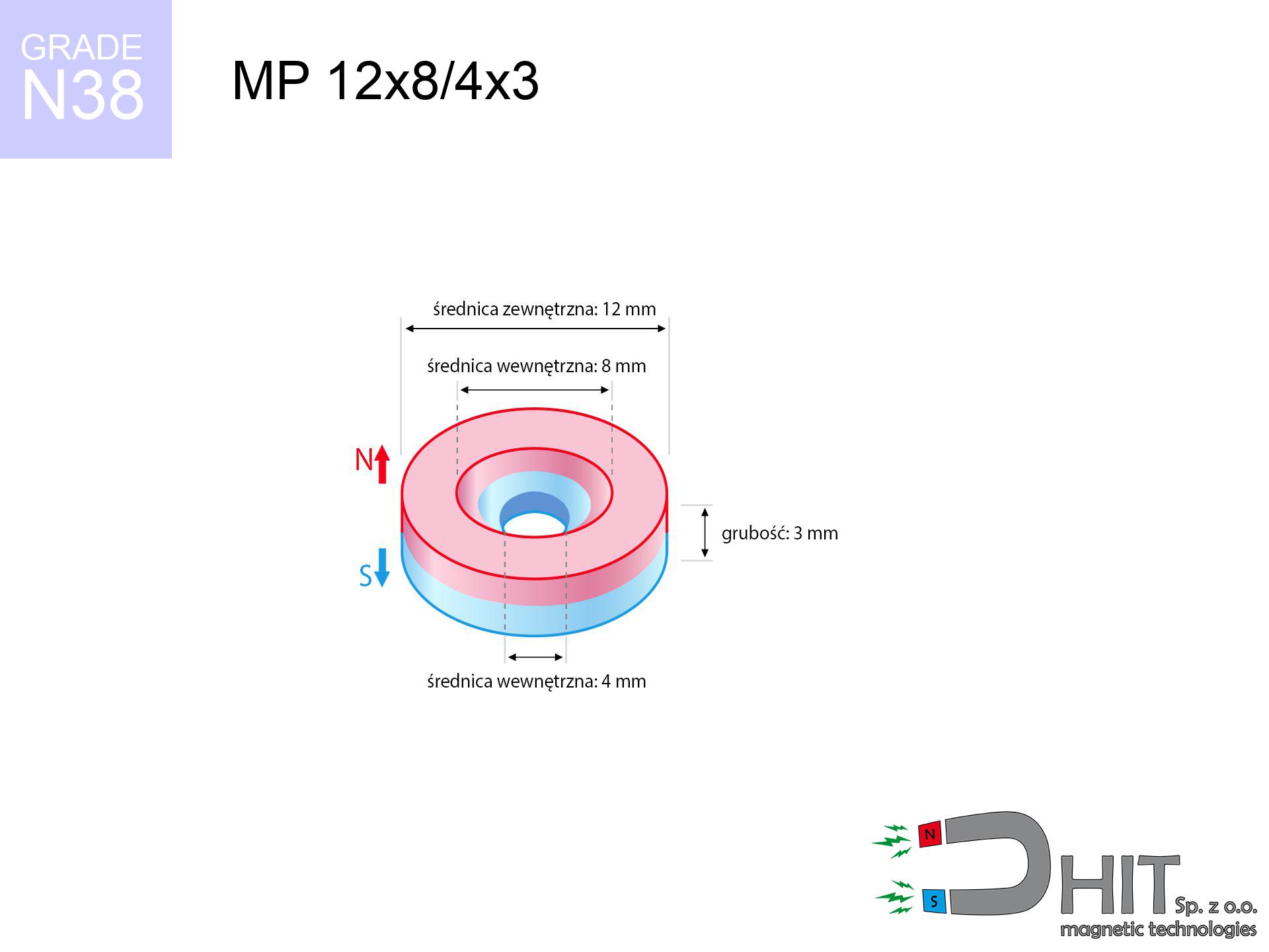
MP 12x8/4x3 / N38 - ring magnet
ring magnet
Catalog no 030395
GTIN/EAN: 5906301812326
Diameter
12 mm [±0,1 mm]
internal diameter Ø
8/4 mm [±0,1 mm]
Height
3 mm [±0,1 mm]
Weight
2.26 g
Magnetization Direction
↑ axial
Load capacity
2.21 kg / 21.72 N
Magnetic Induction
277.09 mT / 2771 Gs
Coating
[NiCuNi] Nickel
1.427 ZŁ with VAT / pcs + price for transport
1.160 ZŁ net + 23% VAT / pcs
bulk discounts:
Need more?Engineering report for this magnet
Full PDF analysis: pull and shear force, effect of distance, temperature and plate thickness, safety distances and the demagnetization curve.
Contact us by phone
+48 22 499 98 98
or send us a note by means of
contact form
the contact section.
Lifting power and form of magnetic components can be reviewed on our
our magnetic calculator.
Order by 14:00 and we’ll ship today!
Physical properties - MP 12x8/4x3 / N38 - ring magnet
Specification / characteristics - MP 12x8/4x3 / N38 - ring magnet
| properties | values |
|---|---|
| Cat. no. | 030395 |
| GTIN/EAN | 5906301812326 |
| Production/Distribution | Dhit sp. z o.o. |
| Country of origin | Poland / China / Germany |
| Customs code | 85059029 |
| Diameter | 12 mm [±0,1 mm] |
| internal diameter Ø | 8/4 mm [±0,1 mm] |
| Height | 3 mm [±0,1 mm] |
| Weight | 2.26 g |
| Magnetization Direction | ↑ axial |
| Load capacity ~ ? | 2.21 kg / 21.72 N |
| Magnetic Induction ~ ? | 277.09 mT / 2771 Gs |
| Coating | [NiCuNi] Nickel |
| Manufacturing Tolerance | ±0.1 mm |
Magnetic properties of material N38
| properties | values | units |
|---|---|---|
| remenance Br [min. - max.] ? | 12.2-12.6 | kGs |
| remenance Br [min. - max.] ? | 1220-1260 | mT |
| coercivity bHc ? | 10.8-11.5 | kOe |
| coercivity bHc ? | 860-915 | kA/m |
| actual internal force iHc | ≥ 12 | kOe |
| actual internal force iHc | ≥ 955 | kA/m |
| energy density [min. - max.] ? | 36-38 | BH max MGOe |
| energy density [min. - max.] ? | 287-303 | BH max KJ/m |
| max. temperature ? | ≤ 80 | °C |
Physical properties of sintered neodymium magnets Nd2Fe14B at 20°C
| properties | values | units |
|---|---|---|
| Vickers hardness | ≥550 | Hv |
| Density | ≥7.4 | g/cm3 |
| Curie Temperature TC | 312 - 380 | °C |
| Curie Temperature TF | 593 - 716 | °F |
| Specific resistance | 150 | μΩ⋅cm |
| Bending strength | 250 | MPa |
| Compressive strength | 1000~1100 | MPa |
| Thermal expansion parallel (∥) to orientation (M) | (3-4) x 10-6 | °C-1 |
| Thermal expansion perpendicular (⊥) to orientation (M) | -(1-3) x 10-6 | °C-1 |
| Young's modulus | 1.7 x 10⁴ | kg/mm² |
Technical analysis of the product - report
These data represent the result of a mathematical simulation. Results were calculated on models for the class Nd2Fe14B. Actual conditions may differ. Please consider these data as a supplementary guide during assembly planning.
Table 1: Static force (force vs gap) - power drop
MP 12x8/4x3 / N38
| Distance (mm) | Induction (Gauss) / mT | Pull Force (kg/lbs/g/N) | Risk Status |
|---|---|---|---|
| 0 mm |
2423 Gs
242.3 mT
|
2.21 kg / 4.87 lbs
2210.0 g / 21.7 N
|
medium risk |
| 1 mm |
2138 Gs
213.8 mT
|
1.72 kg / 3.79 lbs
1720.7 g / 16.9 N
|
weak grip |
| 2 mm |
1786 Gs
178.6 mT
|
1.20 kg / 2.65 lbs
1200.5 g / 11.8 N
|
weak grip |
| 3 mm |
1437 Gs
143.7 mT
|
0.78 kg / 1.71 lbs
777.8 g / 7.6 N
|
weak grip |
| 5 mm |
885 Gs
88.5 mT
|
0.29 kg / 0.65 lbs
294.7 g / 2.9 N
|
weak grip |
| 10 mm |
277 Gs
27.7 mT
|
0.03 kg / 0.06 lbs
28.9 g / 0.3 N
|
weak grip |
| 15 mm |
110 Gs
11.0 mT
|
0.00 kg / 0.01 lbs
4.6 g / 0.0 N
|
weak grip |
| 20 mm |
53 Gs
5.3 mT
|
0.00 kg / 0.00 lbs
1.1 g / 0.0 N
|
weak grip |
| 30 mm |
18 Gs
1.8 mT
|
0.00 kg / 0.00 lbs
0.1 g / 0.0 N
|
weak grip |
| 50 mm |
4 Gs
0.4 mT
|
0.00 kg / 0.00 lbs
0.0 g / 0.0 N
|
weak grip |
Table 2: Vertical hold (vertical surface)
MP 12x8/4x3 / N38
| Distance (mm) | Friction coefficient | Pull Force (kg/lbs/g/N) |
|---|---|---|
| 0 mm | Stal (~0.2) |
0.44 kg / 0.97 lbs
442.0 g / 4.3 N
|
| 1 mm | Stal (~0.2) |
0.34 kg / 0.76 lbs
344.0 g / 3.4 N
|
| 2 mm | Stal (~0.2) |
0.24 kg / 0.53 lbs
240.0 g / 2.4 N
|
| 3 mm | Stal (~0.2) |
0.16 kg / 0.34 lbs
156.0 g / 1.5 N
|
| 5 mm | Stal (~0.2) |
0.06 kg / 0.13 lbs
58.0 g / 0.6 N
|
| 10 mm | Stal (~0.2) |
0.01 kg / 0.01 lbs
6.0 g / 0.1 N
|
| 15 mm | Stal (~0.2) |
0.00 kg / 0.00 lbs
0.0 g / 0.0 N
|
| 20 mm | Stal (~0.2) |
0.00 kg / 0.00 lbs
0.0 g / 0.0 N
|
| 30 mm | Stal (~0.2) |
0.00 kg / 0.00 lbs
0.0 g / 0.0 N
|
| 50 mm | Stal (~0.2) |
0.00 kg / 0.00 lbs
0.0 g / 0.0 N
|
Table 3: Wall mounting (sliding) - behavior on slippery surfaces
MP 12x8/4x3 / N38
| Surface type | Friction coefficient / % Mocy | Max load (kg/lbs/g/N) |
|---|---|---|
| Raw steel |
µ = 0.3
30% Nominalnej Siły
|
0.66 kg / 1.46 lbs
663.0 g / 6.5 N
|
| Painted steel (standard) |
µ = 0.2
20% Nominalnej Siły
|
0.44 kg / 0.97 lbs
442.0 g / 4.3 N
|
| Oily/slippery steel |
µ = 0.1
10% Nominalnej Siły
|
0.22 kg / 0.49 lbs
221.0 g / 2.2 N
|
| Magnet with anti-slip rubber |
µ = 0.5
50% Nominalnej Siły
|
1.11 kg / 2.44 lbs
1105.0 g / 10.8 N
|
Table 4: Steel thickness (substrate influence) - sheet metal selection
MP 12x8/4x3 / N38
| Steel thickness (mm) | % power | Real pull force (kg/lbs/g/N) |
|---|---|---|
| 0.5 mm |
|
0.22 kg / 0.49 lbs
221.0 g / 2.2 N
|
| 1 mm |
|
0.55 kg / 1.22 lbs
552.5 g / 5.4 N
|
| 2 mm |
|
1.11 kg / 2.44 lbs
1105.0 g / 10.8 N
|
| 3 mm |
|
1.66 kg / 3.65 lbs
1657.5 g / 16.3 N
|
| 5 mm |
|
2.21 kg / 4.87 lbs
2210.0 g / 21.7 N
|
| 10 mm |
|
2.21 kg / 4.87 lbs
2210.0 g / 21.7 N
|
| 11 mm |
|
2.21 kg / 4.87 lbs
2210.0 g / 21.7 N
|
| 12 mm |
|
2.21 kg / 4.87 lbs
2210.0 g / 21.7 N
|
Table 5: Thermal stability (material behavior) - power drop
MP 12x8/4x3 / N38
| Ambient temp. (°C) | Power loss | Remaining pull (kg/lbs/g/N) | Status |
|---|---|---|---|
| 20 °C | 0.0% |
2.21 kg / 4.87 lbs
2210.0 g / 21.7 N
|
OK |
| 40 °C | -2.2% |
2.16 kg / 4.77 lbs
2161.4 g / 21.2 N
|
OK |
| 60 °C | -4.4% |
2.11 kg / 4.66 lbs
2112.8 g / 20.7 N
|
|
| 80 °C | -6.6% |
2.06 kg / 4.55 lbs
2064.1 g / 20.2 N
|
|
| 100 °C | -28.8% |
1.57 kg / 3.47 lbs
1573.5 g / 15.4 N
|
Table 6: Two magnets (attraction) - forces in the system
MP 12x8/4x3 / N38
| Gap (mm) | Attraction (kg/lbs) (N-S) | Shear Force (kg/lbs/g/N) | Repulsion (kg/lbs) (N-N) |
|---|---|---|---|
| 0 mm |
3.09 kg / 6.82 lbs
4 010 Gs
|
0.46 kg / 1.02 lbs
464 g / 4.6 N
|
N/A |
| 1 mm |
2.77 kg / 6.12 lbs
4 589 Gs
|
0.42 kg / 0.92 lbs
416 g / 4.1 N
|
2.50 kg / 5.50 lbs
~0 Gs
|
| 2 mm |
2.41 kg / 5.31 lbs
4 276 Gs
|
0.36 kg / 0.80 lbs
361 g / 3.5 N
|
2.17 kg / 4.78 lbs
~0 Gs
|
| 3 mm |
2.03 kg / 4.48 lbs
3 930 Gs
|
0.31 kg / 0.67 lbs
305 g / 3.0 N
|
1.83 kg / 4.04 lbs
~0 Gs
|
| 5 mm |
1.36 kg / 3.00 lbs
3 216 Gs
|
0.20 kg / 0.45 lbs
204 g / 2.0 N
|
1.23 kg / 2.70 lbs
~0 Gs
|
| 10 mm |
0.41 kg / 0.91 lbs
1 770 Gs
|
0.06 kg / 0.14 lbs
62 g / 0.6 N
|
0.37 kg / 0.82 lbs
~0 Gs
|
| 20 mm |
0.04 kg / 0.09 lbs
554 Gs
|
0.01 kg / 0.01 lbs
6 g / 0.1 N
|
0.04 kg / 0.08 lbs
~0 Gs
|
| 50 mm |
0.00 kg / 0.00 lbs
58 Gs
|
0.00 kg / 0.00 lbs
0 g / 0.0 N
|
0.00 kg / 0.00 lbs
~0 Gs
|
| 60 mm |
0.00 kg / 0.00 lbs
35 Gs
|
0.00 kg / 0.00 lbs
0 g / 0.0 N
|
0.00 kg / 0.00 lbs
~0 Gs
|
| 70 mm |
0.00 kg / 0.00 lbs
23 Gs
|
0.00 kg / 0.00 lbs
0 g / 0.0 N
|
0.00 kg / 0.00 lbs
~0 Gs
|
| 80 mm |
0.00 kg / 0.00 lbs
16 Gs
|
0.00 kg / 0.00 lbs
0 g / 0.0 N
|
0.00 kg / 0.00 lbs
~0 Gs
|
| 90 mm |
0.00 kg / 0.00 lbs
11 Gs
|
0.00 kg / 0.00 lbs
0 g / 0.0 N
|
0.00 kg / 0.00 lbs
~0 Gs
|
| 100 mm |
0.00 kg / 0.00 lbs
8 Gs
|
0.00 kg / 0.00 lbs
0 g / 0.0 N
|
0.00 kg / 0.00 lbs
~0 Gs
|
Table 7: Protective zones (electronics) - precautionary measures
MP 12x8/4x3 / N38
| Object / Device | Limit (Gauss) / mT | Safe distance |
|---|---|---|
| Pacemaker | 5 Gs (0.5 mT) | 5.0 cm |
| Hearing aid | 10 Gs (1.0 mT) | 4.0 cm |
| Timepiece | 20 Gs (2.0 mT) | 3.0 cm |
| Phone / Smartphone | 40 Gs (4.0 mT) | 2.5 cm |
| Car key | 50 Gs (5.0 mT) | 2.5 cm |
| Payment card | 400 Gs (40.0 mT) | 1.0 cm |
| HDD hard drive | 600 Gs (60.0 mT) | 1.0 cm |
Table 8: Impact energy (cracking risk) - collision effects
MP 12x8/4x3 / N38
| Start from (mm) | Speed (km/h) | Energy (J) | Predicted outcome |
|---|---|---|---|
| 10 mm |
31.79 km/h
(8.83 m/s)
|
0.09 J | |
| 30 mm |
54.63 km/h
(15.17 m/s)
|
0.26 J | |
| 50 mm |
70.52 km/h
(19.59 m/s)
|
0.43 J | |
| 100 mm |
99.73 km/h
(27.70 m/s)
|
0.87 J |
Table 9: Corrosion resistance
MP 12x8/4x3 / N38
| Technical parameter | Value / Description |
|---|---|
| Coating type | [NiCuNi] Nickel |
| Layer structure | Nickel - Copper - Nickel |
| Layer thickness | 10-20 µm |
| Salt spray test (SST) ? | 24 h |
| Recommended environment | Indoors only (dry) |
Table 10: Electrical data (Pc)
MP 12x8/4x3 / N38
| Parameter | Value | SI Unit / Description |
|---|---|---|
| Magnetic Flux | 2 466 Mx | 24.7 µWb |
| Pc Coefficient | 0.32 | Low (Flat) |
Table 11: Hydrostatics and buoyancy
MP 12x8/4x3 / N38
| Environment | Effective steel pull | Effect |
|---|---|---|
| Air (land) | 2.21 kg | Standard |
| Water (riverbed) |
2.53 kg
(+0.32 kg buoyancy gain)
|
+14.5% |
1. Vertical hold
*Caution: On a vertical surface, the magnet holds only approx. 20-30% of its max power.
2. Plate thickness effect
*Thin metal sheet (e.g. 0.5mm PC case) significantly weakens the holding force.
3. Power loss vs temp
*For N38 material, the critical limit is 80°C.
4. Demagnetization curve and operating point (B-H)
chart generated for the permeance coefficient Pc (Permeance Coefficient) = 0.32
This simulation demonstrates the magnetic stability of the selected magnet under specific geometric conditions. The solid red line represents the demagnetization curve (material potential), while the dashed blue line is the load line based on the magnet's geometry. The Pc (Permeance Coefficient), also known as the load line slope, is a dimensionless value that describes the relationship between the magnet's shape and its magnetic stability. The intersection of these two lines (the black dot) is the operating point — it determines the actual magnetic flux density generated by the magnet in this specific configuration. A higher Pc value means the magnet is more 'slender' (tall relative to its area), resulting in a higher operating point and better resistance to irreversible demagnetization caused by external fields or temperature. A value of 0.42 is relatively low (typical for flat magnets), meaning the operating point is closer to the 'knee' of the curve — caution is advised when operating at temperatures near the maximum limit to avoid strength loss.
Elemental analysis
| iron (Fe) | 64% – 68% |
| neodymium (Nd) | 29% – 32% |
| boron (B) | 1.1% – 1.2% |
| dysprosium (Dy) | 0.5% – 2.0% |
| coating (Ni-Cu-Ni) | < 0.05% |
Ecology and recycling (GPSR)
| recyclability (EoL) | 100% |
| recycled raw materials | ~10% (pre-cons) |
| carbon footprint | low / zredukowany |
| waste code (EWC) | 16 02 16 |
Other deals

![UMP 135x40 [M10+M12] GW F600 Lina / N38 - search holder](https://cdn3.dhit.pl/graphics/products/ump-135x40-m10+m12-gw-f600-+lina-sej.jpg "UMP 135x40 [M10+M12] GW F600 Lina / N38 - search holder")


Strengths as well as weaknesses of Nd2Fe14B magnets.
Strengths
- They have stable power, and over around ten years their attraction force decreases symbolically – ~1% (according to theory),
- They are resistant to demagnetization induced by external field influence,
- The use of an aesthetic finish of noble metals (nickel, gold, silver) causes the element to be more visually attractive,
- Neodymium magnets create maximum magnetic induction on a contact point, which allows for strong attraction,
- Made from properly selected components, these magnets show impressive resistance to high heat, enabling them to function (depending on their shape) at temperatures up to 230°C and above...
- Possibility of accurate forming and optimizing to precise applications,
- Versatile presence in high-tech industry – they serve a role in mass storage devices, electromotive mechanisms, diagnostic systems, and complex engineering applications.
- Relatively small size with high pulling force – neodymium magnets offer high power in compact dimensions, which enables their usage in miniature devices
Weaknesses
- They are prone to damage upon heavy impacts. To avoid cracks, it is worth protecting magnets in special housings. Such protection not only shields the magnet but also improves its resistance to damage
- NdFeB magnets demagnetize when exposed to high temperatures. After reaching 80°C, many of them experience permanent drop of strength (a factor is the shape as well as dimensions of the magnet). We offer magnets specially adapted to work at temperatures up to 230°C marked [AH], which are extremely resistant to heat
- Due to the susceptibility of magnets to corrosion in a humid environment, we advise using waterproof magnets made of rubber, plastic or other material stable to moisture, when using outdoors
- Limited ability of producing threads in the magnet and complicated forms - preferred is cover - mounting mechanism.
- Potential hazard to health – tiny shards of magnets are risky, when accidentally swallowed, which becomes key in the context of child safety. Additionally, small elements of these magnets can complicate diagnosis medical after entering the body.
- High unit price – neodymium magnets cost more than other types of magnets (e.g. ferrite), which can limit application in large quantities
Holding force characteristics
Optimal lifting capacity of a neodymium magnet – what affects it?
- using a plate made of mild steel, serving as a ideal flux conductor
- with a cross-section minimum 10 mm
- with a plane free of scratches
- with direct contact (without paint)
- under axial force direction (90-degree angle)
- in stable room temperature
Determinants of lifting force in real conditions
- Space between surfaces – even a fraction of a millimeter of separation (caused e.g. by veneer or dirt) diminishes the pulling force, often by half at just 0.5 mm.
- Force direction – declared lifting capacity refers to detachment vertically. When slipping, the magnet exhibits significantly lower power (often approx. 20-30% of nominal force).
- Plate thickness – insufficiently thick steel does not accept the full field, causing part of the flux to be escaped into the air.
- Metal type – not every steel reacts the same. High carbon content worsen the attraction effect.
- Surface finish – full contact is obtained only on smooth steel. Any scratches and bumps reduce the real contact area, weakening the magnet.
- Temperature – heating the magnet results in weakening of force. It is worth remembering the maximum operating temperature for a given model.
Lifting capacity testing was performed on plates with a smooth surface of suitable thickness, under perpendicular forces, in contrast under attempts to slide the magnet the load capacity is reduced by as much as fivefold. Moreover, even a minimal clearance between the magnet’s surface and the plate reduces the lifting capacity.
Precautions when working with NdFeB magnets
GPS Danger
Be aware: rare earth magnets produce a field that confuses precision electronics. Maintain a safe distance from your phone, tablet, and GPS.
Do not underestimate power
Handle with care. Neodymium magnets attract from a long distance and snap with huge force, often quicker than you can move away.
Pinching danger
Mind your fingers. Two powerful magnets will join immediately with a force of several hundred kilograms, destroying anything in their path. Be careful!
Life threat
For implant holders: Strong magnetic fields disrupt medical devices. Keep minimum 30 cm distance or ask another person to work with the magnets.
Danger to the youngest
Strictly store magnets away from children. Ingestion danger is high, and the consequences of magnets clamping inside the body are fatal.
Protect data
Avoid bringing magnets close to a purse, laptop, or screen. The magnetism can irreversibly ruin these devices and erase data from cards.
Mechanical processing
Machining of neodymium magnets carries a risk of fire hazard. Neodymium dust oxidizes rapidly with oxygen and is hard to extinguish.
Maximum temperature
Keep cool. Neodymium magnets are sensitive to heat. If you need operation above 80°C, look for HT versions (H, SH, UH).
Allergic reactions
Certain individuals suffer from a hypersensitivity to Ni, which is the typical protective layer for neodymium magnets. Frequent touching might lead to dermatitis. We suggest use protective gloves.
Protective goggles
Protect your eyes. Magnets can explode upon uncontrolled impact, ejecting shards into the air. Wear goggles.
Tabela kosztu i czasu dostawy
Płatność przed wysyłką:

GLS kurier
Przesyłka będzie u Ciebie za 2-3 dni
14.99 ZŁ

InPost Paczkomaty 24/7
Przesyłka będzie u Ciebie za 1-2 dni
12.30 ZŁ
Płatność przy odbiorze (pobranie):
GLS kurier
Przesyłka będzie u Ciebie za 1-2 dni
23.00 ZŁ
Rate the product
Your rating