

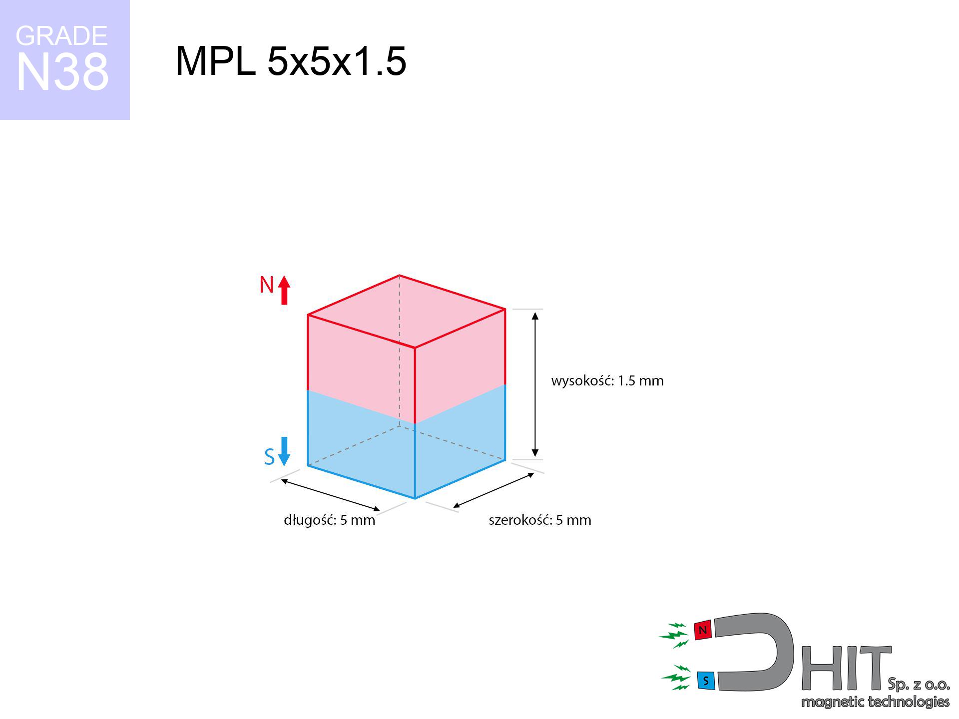
MPL 5x5x1.5 / N38 - lamellar magnet
lamellar magnet
Catalog no 020172
GTIN/EAN: 5906301811787
length
5 mm [±0,1 mm]
Width
5 mm [±0,1 mm]
Height
1.5 mm [±0,1 mm]
Weight
0.28 g
Magnetization Direction
↑ axial
Load capacity
0.58 kg / 5.68 N
Magnetic Induction
293.49 mT / 2935 Gs
Coating
[NiCuNi] Nickel
0.1845 ZŁ with VAT / pcs + price for transport
0.1500 ZŁ net + 23% VAT / pcs
bulk discounts:
Need more?
Pick up the phone and ask
+48 22 499 98 98
or get in touch by means of
form
through our site.
Weight and appearance of a neodymium magnet can be verified with our
magnetic calculator.
Order by 14:00 and we’ll ship today!
Product card - MPL 5x5x1.5 / N38 - lamellar magnet
Specification / characteristics - MPL 5x5x1.5 / N38 - lamellar magnet
| properties | values |
|---|---|
| Cat. no. | 020172 |
| GTIN/EAN | 5906301811787 |
| Production/Distribution | Dhit sp. z o.o. |
| Country of origin | Poland / China / Germany |
| Customs code | 85059029 |
| length | 5 mm [±0,1 mm] |
| Width | 5 mm [±0,1 mm] |
| Height | 1.5 mm [±0,1 mm] |
| Weight | 0.28 g |
| Magnetization Direction | ↑ axial |
| Load capacity ~ ? | 0.58 kg / 5.68 N |
| Magnetic Induction ~ ? | 293.49 mT / 2935 Gs |
| Coating | [NiCuNi] Nickel |
| Manufacturing Tolerance | ±0.1 mm |
Magnetic properties of material N38
| properties | values | units |
|---|---|---|
| remenance Br [min. - max.] ? | 12.2-12.6 | kGs |
| remenance Br [min. - max.] ? | 1220-1260 | mT |
| coercivity bHc ? | 10.8-11.5 | kOe |
| coercivity bHc ? | 860-915 | kA/m |
| actual internal force iHc | ≥ 12 | kOe |
| actual internal force iHc | ≥ 955 | kA/m |
| energy density [min. - max.] ? | 36-38 | BH max MGOe |
| energy density [min. - max.] ? | 287-303 | BH max KJ/m |
| max. temperature ? | ≤ 80 | °C |
Physical properties of sintered neodymium magnets Nd2Fe14B at 20°C
| properties | values | units |
|---|---|---|
| Vickers hardness | ≥550 | Hv |
| Density | ≥7.4 | g/cm3 |
| Curie Temperature TC | 312 - 380 | °C |
| Curie Temperature TF | 593 - 716 | °F |
| Specific resistance | 150 | μΩ⋅cm |
| Bending strength | 250 | MPa |
| Compressive strength | 1000~1100 | MPa |
| Thermal expansion parallel (∥) to orientation (M) | (3-4) x 10-6 | °C-1 |
| Thermal expansion perpendicular (⊥) to orientation (M) | -(1-3) x 10-6 | °C-1 |
| Young's modulus | 1.7 x 10⁴ | kg/mm² |
Engineering modeling of the magnet - data
Presented data represent the outcome of a mathematical simulation. Values are based on algorithms for the material Nd2Fe14B. Actual conditions might slightly differ. Please consider these calculations as a supplementary guide when designing systems.
Table 1: Static pull force (force vs distance) - power drop
MPL 5x5x1.5 / N38
| Distance (mm) | Induction (Gauss) / mT | Pull Force (kg/lbs/g/N) | Risk Status |
|---|---|---|---|
| 0 mm |
2932 Gs
293.2 mT
|
0.58 kg / 1.28 pounds
580.0 g / 5.7 N
|
weak grip |
| 1 mm |
2036 Gs
203.6 mT
|
0.28 kg / 0.62 pounds
279.6 g / 2.7 N
|
weak grip |
| 2 mm |
1228 Gs
122.8 mT
|
0.10 kg / 0.22 pounds
101.7 g / 1.0 N
|
weak grip |
| 3 mm |
727 Gs
72.7 mT
|
0.04 kg / 0.08 pounds
35.7 g / 0.3 N
|
weak grip |
| 5 mm |
285 Gs
28.5 mT
|
0.01 kg / 0.01 pounds
5.5 g / 0.1 N
|
weak grip |
| 10 mm |
54 Gs
5.4 mT
|
0.00 kg / 0.00 pounds
0.2 g / 0.0 N
|
weak grip |
| 15 mm |
18 Gs
1.8 mT
|
0.00 kg / 0.00 pounds
0.0 g / 0.0 N
|
weak grip |
| 20 mm |
8 Gs
0.8 mT
|
0.00 kg / 0.00 pounds
0.0 g / 0.0 N
|
weak grip |
| 30 mm |
3 Gs
0.3 mT
|
0.00 kg / 0.00 pounds
0.0 g / 0.0 N
|
weak grip |
| 50 mm |
1 Gs
0.1 mT
|
0.00 kg / 0.00 pounds
0.0 g / 0.0 N
|
weak grip |
Table 2: Shear capacity (vertical surface)
MPL 5x5x1.5 / N38
| Distance (mm) | Friction coefficient | Pull Force (kg/lbs/g/N) |
|---|---|---|
| 0 mm | Stal (~0.2) |
0.12 kg / 0.26 pounds
116.0 g / 1.1 N
|
| 1 mm | Stal (~0.2) |
0.06 kg / 0.12 pounds
56.0 g / 0.5 N
|
| 2 mm | Stal (~0.2) |
0.02 kg / 0.04 pounds
20.0 g / 0.2 N
|
| 3 mm | Stal (~0.2) |
0.01 kg / 0.02 pounds
8.0 g / 0.1 N
|
| 5 mm | Stal (~0.2) |
0.00 kg / 0.00 pounds
2.0 g / 0.0 N
|
| 10 mm | Stal (~0.2) |
0.00 kg / 0.00 pounds
0.0 g / 0.0 N
|
| 15 mm | Stal (~0.2) |
0.00 kg / 0.00 pounds
0.0 g / 0.0 N
|
| 20 mm | Stal (~0.2) |
0.00 kg / 0.00 pounds
0.0 g / 0.0 N
|
| 30 mm | Stal (~0.2) |
0.00 kg / 0.00 pounds
0.0 g / 0.0 N
|
| 50 mm | Stal (~0.2) |
0.00 kg / 0.00 pounds
0.0 g / 0.0 N
|
Table 3: Wall mounting (shearing) - behavior on slippery surfaces
MPL 5x5x1.5 / N38
| Surface type | Friction coefficient / % Mocy | Max load (kg/lbs/g/N) |
|---|---|---|
| Raw steel |
µ = 0.3
30% Nominalnej Siły
|
0.17 kg / 0.38 pounds
174.0 g / 1.7 N
|
| Painted steel (standard) |
µ = 0.2
20% Nominalnej Siły
|
0.12 kg / 0.26 pounds
116.0 g / 1.1 N
|
| Oily/slippery steel |
µ = 0.1
10% Nominalnej Siły
|
0.06 kg / 0.13 pounds
58.0 g / 0.6 N
|
| Magnet with anti-slip rubber |
µ = 0.5
50% Nominalnej Siły
|
0.29 kg / 0.64 pounds
290.0 g / 2.8 N
|
Table 4: Material efficiency (substrate influence) - sheet metal selection
MPL 5x5x1.5 / N38
| Steel thickness (mm) | % power | Real pull force (kg/lbs/g/N) |
|---|---|---|
| 0.5 mm |
|
0.06 kg / 0.13 pounds
58.0 g / 0.6 N
|
| 1 mm |
|
0.15 kg / 0.32 pounds
145.0 g / 1.4 N
|
| 2 mm |
|
0.29 kg / 0.64 pounds
290.0 g / 2.8 N
|
| 3 mm |
|
0.43 kg / 0.96 pounds
435.0 g / 4.3 N
|
| 5 mm |
|
0.58 kg / 1.28 pounds
580.0 g / 5.7 N
|
| 10 mm |
|
0.58 kg / 1.28 pounds
580.0 g / 5.7 N
|
| 11 mm |
|
0.58 kg / 1.28 pounds
580.0 g / 5.7 N
|
| 12 mm |
|
0.58 kg / 1.28 pounds
580.0 g / 5.7 N
|
Table 5: Working in heat (stability) - power drop
MPL 5x5x1.5 / N38
| Ambient temp. (°C) | Power loss | Remaining pull (kg/lbs/g/N) | Status |
|---|---|---|---|
| 20 °C | 0.0% |
0.58 kg / 1.28 pounds
580.0 g / 5.7 N
|
OK |
| 40 °C | -2.2% |
0.57 kg / 1.25 pounds
567.2 g / 5.6 N
|
OK |
| 60 °C | -4.4% |
0.55 kg / 1.22 pounds
554.5 g / 5.4 N
|
|
| 80 °C | -6.6% |
0.54 kg / 1.19 pounds
541.7 g / 5.3 N
|
|
| 100 °C | -28.8% |
0.41 kg / 0.91 pounds
413.0 g / 4.1 N
|
Table 6: Two magnets (attraction) - forces in the system
MPL 5x5x1.5 / N38
| Gap (mm) | Attraction (kg/lbs) (N-S) | Shear Strength (kg/lbs/g/N) | Repulsion (kg/lbs) (N-N) |
|---|---|---|---|
| 0 mm |
1.33 kg / 2.92 pounds
4 518 Gs
|
0.20 kg / 0.44 pounds
199 g / 1.9 N
|
N/A |
| 1 mm |
0.97 kg / 2.15 pounds
5 027 Gs
|
0.15 kg / 0.32 pounds
146 g / 1.4 N
|
0.88 kg / 1.93 pounds
~0 Gs
|
| 2 mm |
0.64 kg / 1.41 pounds
4 071 Gs
|
0.10 kg / 0.21 pounds
96 g / 0.9 N
|
0.57 kg / 1.27 pounds
~0 Gs
|
| 3 mm |
0.39 kg / 0.86 pounds
3 188 Gs
|
0.06 kg / 0.13 pounds
59 g / 0.6 N
|
0.35 kg / 0.78 pounds
~0 Gs
|
| 5 mm |
0.14 kg / 0.30 pounds
1 886 Gs
|
0.02 kg / 0.05 pounds
21 g / 0.2 N
|
0.12 kg / 0.27 pounds
~0 Gs
|
| 10 mm |
0.01 kg / 0.03 pounds
569 Gs
|
0.00 kg / 0.00 pounds
2 g / 0.0 N
|
0.01 kg / 0.02 pounds
~0 Gs
|
| 20 mm |
0.00 kg / 0.00 pounds
108 Gs
|
0.00 kg / 0.00 pounds
0 g / 0.0 N
|
0.00 kg / 0.00 pounds
~0 Gs
|
| 50 mm |
0.00 kg / 0.00 pounds
9 Gs
|
0.00 kg / 0.00 pounds
0 g / 0.0 N
|
0.00 kg / 0.00 pounds
~0 Gs
|
| 60 mm |
0.00 kg / 0.00 pounds
5 Gs
|
0.00 kg / 0.00 pounds
0 g / 0.0 N
|
0.00 kg / 0.00 pounds
~0 Gs
|
| 70 mm |
0.00 kg / 0.00 pounds
3 Gs
|
0.00 kg / 0.00 pounds
0 g / 0.0 N
|
0.00 kg / 0.00 pounds
~0 Gs
|
| 80 mm |
0.00 kg / 0.00 pounds
2 Gs
|
0.00 kg / 0.00 pounds
0 g / 0.0 N
|
0.00 kg / 0.00 pounds
~0 Gs
|
| 90 mm |
0.00 kg / 0.00 pounds
2 Gs
|
0.00 kg / 0.00 pounds
0 g / 0.0 N
|
0.00 kg / 0.00 pounds
~0 Gs
|
| 100 mm |
0.00 kg / 0.00 pounds
1 Gs
|
0.00 kg / 0.00 pounds
0 g / 0.0 N
|
0.00 kg / 0.00 pounds
~0 Gs
|
Table 7: Protective zones (implants) - precautionary measures
MPL 5x5x1.5 / N38
| Object / Device | Limit (Gauss) / mT | Safe distance |
|---|---|---|
| Pacemaker | 5 Gs (0.5 mT) | 2.5 cm |
| Hearing aid | 10 Gs (1.0 mT) | 2.0 cm |
| Mechanical watch | 20 Gs (2.0 mT) | 1.5 cm |
| Mobile device | 40 Gs (4.0 mT) | 1.5 cm |
| Car key | 50 Gs (5.0 mT) | 1.5 cm |
| Payment card | 400 Gs (40.0 mT) | 0.5 cm |
| HDD hard drive | 600 Gs (60.0 mT) | 0.5 cm |
Table 8: Collisions (kinetic energy) - warning
MPL 5x5x1.5 / N38
| Start from (mm) | Speed (km/h) | Energy (J) | Predicted outcome |
|---|---|---|---|
| 10 mm |
45.91 km/h
(12.75 m/s)
|
0.02 J | |
| 30 mm |
79.50 km/h
(22.08 m/s)
|
0.07 J | |
| 50 mm |
102.64 km/h
(28.51 m/s)
|
0.11 J | |
| 100 mm |
145.15 km/h
(40.32 m/s)
|
0.23 J |
Table 9: Surface protection spec
MPL 5x5x1.5 / N38
| Technical parameter | Value / Description |
|---|---|
| Coating type | [NiCuNi] Nickel |
| Layer structure | Nickel - Copper - Nickel |
| Layer thickness | 10-20 µm |
| Salt spray test (SST) ? | 24 h |
| Recommended environment | Indoors only (dry) |
Table 10: Construction data (Pc)
MPL 5x5x1.5 / N38
| Parameter | Value | SI Unit / Description |
|---|---|---|
| Magnetic Flux | 799 Mx | 8.0 µWb |
| Pc Coefficient | 0.36 | Low (Flat) |
Table 11: Physics of underwater searching
MPL 5x5x1.5 / N38
| Environment | Effective steel pull | Effect |
|---|---|---|
| Air (land) | 0.58 kg | Standard |
| Water (riverbed) |
0.66 kg
(+0.08 kg buoyancy gain)
|
+14.5% |
1. Vertical hold
*Note: On a vertical surface, the magnet retains merely approx. 20-30% of its perpendicular strength.
2. Steel saturation
*Thin steel (e.g. 0.5mm PC case) significantly reduces the holding force.
3. Temperature resistance
*For N38 grade, the critical limit is 80°C.
4. Demagnetization curve and operating point (B-H)
chart generated for the permeance coefficient Pc (Permeance Coefficient) = 0.36
This simulation demonstrates the magnetic stability of the selected magnet under specific geometric conditions. The solid red line represents the demagnetization curve (material potential), while the dashed blue line is the load line based on the magnet's geometry. The Pc (Permeance Coefficient), also known as the load line slope, is a dimensionless value that describes the relationship between the magnet's shape and its magnetic stability. The intersection of these two lines (the black dot) is the operating point — it determines the actual magnetic flux density generated by the magnet in this specific configuration. A higher Pc value means the magnet is more 'slender' (tall relative to its area), resulting in a higher operating point and better resistance to irreversible demagnetization caused by external fields or temperature. A value of 0.42 is relatively low (typical for flat magnets), meaning the operating point is closer to the 'knee' of the curve — caution is advised when operating at temperatures near the maximum limit to avoid strength loss.
Material specification
| iron (Fe) | 64% – 68% |
| neodymium (Nd) | 29% – 32% |
| boron (B) | 1.1% – 1.2% |
| dysprosium (Dy) | 0.5% – 2.0% |
| coating (Ni-Cu-Ni) | < 0.05% |
Sustainability
| recyclability (EoL) | 100% |
| recycled raw materials | ~10% (pre-cons) |
| carbon footprint | low / zredukowany |
| waste code (EWC) | 16 02 16 |
View also offers
![UMP 94x40 [3xM10] GW F550 Silver Black Lina / N52 - search holder](https://cdn3.dhit.pl/graphics/products/ump-94x40-3xm10-gw-f550-lina-gub.jpg "UMP 94x40 [3xM10] GW F550 Silver Black Lina / N52 - search holder")

![UMP 97x40 [M8+M10] GW F300 kg / N38 - search holder](https://cdn3.dhit.pl/graphics/products/ump97x40-m8+m10-gw-f-300-kg-kic.jpg "UMP 97x40 [M8+M10] GW F300 kg / N38 - search holder")

Strengths and weaknesses of neodymium magnets.
Benefits
- They have unchanged lifting capacity, and over around 10 years their performance decreases symbolically – ~1% (in testing),
- They feature excellent resistance to magnetic field loss due to external magnetic sources,
- A magnet with a metallic nickel surface is more attractive,
- Magnetic induction on the surface of the magnet turns out to be very high,
- Through (appropriate) combination of ingredients, they can achieve high thermal strength, enabling functioning at temperatures reaching 230°C and above...
- Possibility of precise modeling and adapting to concrete requirements,
- Universal use in electronics industry – they are commonly used in hard drives, electric motors, advanced medical instruments, as well as modern systems.
- Relatively small size with high pulling force – neodymium magnets offer strong magnetic field in tiny dimensions, which enables their usage in compact constructions
Limitations
- At strong impacts they can break, therefore we advise placing them in steel cases. A metal housing provides additional protection against damage and increases the magnet's durability.
- We warn that neodymium magnets can lose their power at high temperatures. To prevent this, we advise our specialized [AH] magnets, which work effectively even at 230°C.
- Magnets exposed to a humid environment can rust. Therefore during using outdoors, we recommend using waterproof magnets made of rubber, plastic or other material resistant to moisture
- We recommend cover - magnetic holder, due to difficulties in creating nuts inside the magnet and complex shapes.
- Possible danger resulting from small fragments of magnets can be dangerous, in case of ingestion, which becomes key in the context of child safety. It is also worth noting that small components of these products can disrupt the diagnostic process medical in case of swallowing.
- Higher cost of purchase is a significant factor to consider compared to ceramic magnets, especially in budget applications
Lifting parameters
Detachment force of the magnet in optimal conditions – what contributes to it?
- with the contact of a sheet made of low-carbon steel, guaranteeing maximum field concentration
- possessing a thickness of min. 10 mm to avoid saturation
- with a surface free of scratches
- without the slightest air gap between the magnet and steel
- for force acting at a right angle (in the magnet axis)
- at room temperature
Practical lifting capacity: influencing factors
- Space between surfaces – even a fraction of a millimeter of separation (caused e.g. by veneer or dirt) significantly weakens the magnet efficiency, often by half at just 0.5 mm.
- Angle of force application – maximum parameter is reached only during pulling at a 90° angle. The resistance to sliding of the magnet along the plate is usually many times lower (approx. 1/5 of the lifting capacity).
- Wall thickness – thin material does not allow full use of the magnet. Magnetic flux passes through the material instead of converting into lifting capacity.
- Steel type – low-carbon steel gives the best results. Alloy admixtures reduce magnetic permeability and lifting capacity.
- Surface structure – the smoother and more polished the surface, the larger the contact zone and stronger the hold. Unevenness creates an air distance.
- Thermal factor – high temperature weakens pulling force. Too high temperature can permanently demagnetize the magnet.
Lifting capacity was determined using a steel plate with a smooth surface of suitable thickness (min. 20 mm), under perpendicular pulling force, whereas under attempts to slide the magnet the lifting capacity is smaller. In addition, even a minimal clearance between the magnet and the plate reduces the lifting capacity.
Warnings
Electronic devices
Intense magnetic fields can corrupt files on credit cards, hard drives, and storage devices. Stay away of min. 10 cm.
Allergic reactions
Some people suffer from a hypersensitivity to Ni, which is the common plating for neodymium magnets. Extended handling can result in skin redness. It is best to use safety gloves.
No play value
Only for adults. Small elements pose a choking risk, leading to severe trauma. Keep away from children and animals.
Thermal limits
Standard neodymium magnets (N-type) lose power when the temperature exceeds 80°C. Damage is permanent.
Danger to pacemakers
Individuals with a heart stimulator must maintain an absolute distance from magnets. The magnetism can stop the functioning of the life-saving device.
Dust explosion hazard
Fire hazard: Rare earth powder is explosive. Do not process magnets without safety gear as this risks ignition.
Shattering risk
Despite metallic appearance, the material is brittle and cannot withstand shocks. Do not hit, as the magnet may crumble into sharp, dangerous pieces.
Serious injuries
Pinching hazard: The pulling power is so immense that it can result in blood blisters, crushing, and broken bones. Use thick gloves.
Phone sensors
A strong magnetic field disrupts the operation of magnetometers in smartphones and GPS navigation. Keep magnets close to a smartphone to prevent damaging the sensors.
Do not underestimate power
Use magnets consciously. Their immense force can surprise even experienced users. Plan your moves and do not underestimate their power.
Tabela kosztu i czasu dostawy
Płatność przed wysyłką:

GLS kurier
Przesyłka będzie u Ciebie za 2-3 dni
14.99 ZŁ

InPost Paczkomaty 24/7
Przesyłka będzie u Ciebie za 1-2 dni
12.30 ZŁ
Płatność przy odbiorze (pobranie):
GLS kurier
Przesyłka będzie u Ciebie za 1-2 dni
23.00 ZŁ
Rate the product
Your rating