

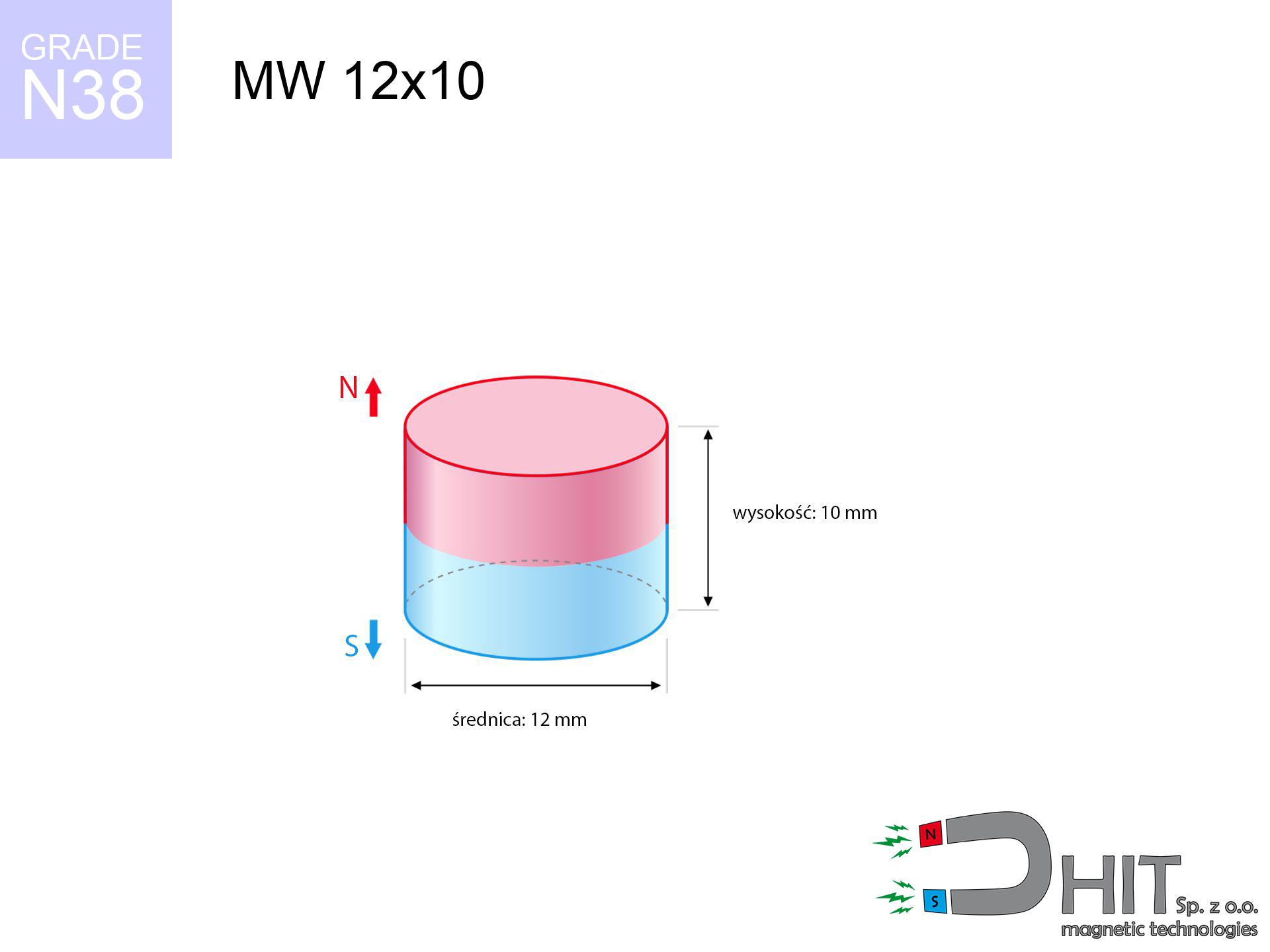
MW 12x10 / N38 - cylindrical magnet
cylindrical magnet
Catalog no 010016
GTIN/EAN: 5906301810155
- Diameter Ø
- 12 mm [±0,1 mm]
- Height
- 10 mm [±0,1 mm]
- Weight
- 8.48 g
- Magnetization Direction
- ↑ axial
- Coating
- [NiCuNi] Nickel
3.03 zł with VAT / pcs + price for transport
2.46 zł net + 23% VAT / pcs
bulk discounts:
Need more?Engineering report for this magnet
Full PDF analysis: pull and shear force, effect of distance, temperature and plate thickness, safety distances and the demagnetization curve.
Call us
+48 22 499 98 98
otherwise get in touch via
contact form
the contact form page.
Parameters along with form of a neodymium magnet can be verified with our
power calculator.
Orders placed before 14:00 will be shipped the same business day.
Technical data - MW 12x10 / N38 - cylindrical magnet
Specification / characteristics - MW 12x10 / N38 - cylindrical magnet
| properties | values |
|---|---|
| Cat. no. | 010016 |
| GTIN/EAN | 5906301810155 |
| Production/Distribution | Dhit sp. z o.o. |
| Country of origin | Poland / China / Germany |
| Customs code | 85059029 |
| Diameter Ø | 12 mm [±0,1 mm] |
| Height | 10 mm [±0,1 mm] |
| Weight | 8.48 g |
| Magnetization Direction | ↑ axial |
| Load capacity ~ ? | 4.83 kg / 47.41 N |
| Magnetic Induction ~ ? | 531.09 mT / 5311 Gs |
| Coating | [NiCuNi] Nickel |
| Manufacturing Tolerance | ±0.1 mm |
Magnetic properties of material N38
| properties | values | units |
|---|---|---|
| remenance Br [min. - max.] ? | 12.2-12.6 | kGs |
| remenance Br [min. - max.] ? | 1220-1260 | mT |
| coercivity bHc ? | 10.8-11.5 | kOe |
| coercivity bHc ? | 860-915 | kA/m |
| actual internal force iHc | ≥ 12 | kOe |
| actual internal force iHc | ≥ 955 | kA/m |
| energy density [min. - max.] ? | 36-38 | BH max MGOe |
| energy density [min. - max.] ? | 287-303 | BH max KJ/m |
| max. temperature ? | ≤ 80 | °C |
Physical properties of sintered neodymium magnets Nd2Fe14B at 20°C
| properties | values | units |
|---|---|---|
| Vickers hardness | ≥550 | Hv |
| Density | ≥7.4 | g/cm3 |
| Curie Temperature TC | 312 - 380 | °C |
| Curie Temperature TF | 593 - 716 | °F |
| Specific resistance | 150 | μΩ⋅cm |
| Bending strength | 250 | MPa |
| Compressive strength | 1000~1100 | MPa |
| Thermal expansion parallel (∥) to orientation (M) | (3-4) x 10-6 | °C-1 |
| Thermal expansion perpendicular (⊥) to orientation (M) | -(1-3) x 10-6 | °C-1 |
| Young's modulus | 1.7 x 10⁴ | kg/mm² |
Engineering analysis of the product - data
These values are the result of a engineering calculation. Values were calculated on models for the material Nd2Fe14B. Real-world conditions may differ from theoretical values. Treat these calculations as a preliminary roadmap when designing systems.
Table 1: Static force (pull vs distance) - characteristics
MW 12x10 / N38
| Distance (mm) | Induction (Gauss) / mT | Pull Force (kg/lbs/g/N) | Risk Status |
|---|---|---|---|
| 0 mm |
5308 Gs
530.8 mT
|
4.83 kg / 10.65 pounds
4830.0 g / 47.4 N
|
warning |
| 1 mm |
4424 Gs
442.4 mT
|
3.36 kg / 7.40 pounds
3355.3 g / 32.9 N
|
warning |
| 2 mm |
3585 Gs
358.5 mT
|
2.20 kg / 4.86 pounds
2203.4 g / 21.6 N
|
warning |
| 3 mm |
2857 Gs
285.7 mT
|
1.40 kg / 3.08 pounds
1399.2 g / 13.7 N
|
safe |
| 5 mm |
1787 Gs
178.7 mT
|
0.55 kg / 1.21 pounds
547.8 g / 5.4 N
|
safe |
| 10 mm |
622 Gs
62.2 mT
|
0.07 kg / 0.15 pounds
66.3 g / 0.7 N
|
safe |
| 15 mm |
272 Gs
27.2 mT
|
0.01 kg / 0.03 pounds
12.7 g / 0.1 N
|
safe |
| 20 mm |
141 Gs
14.1 mT
|
0.00 kg / 0.01 pounds
3.4 g / 0.0 N
|
safe |
| 30 mm |
52 Gs
5.2 mT
|
0.00 kg / 0.00 pounds
0.5 g / 0.0 N
|
safe |
| 50 mm |
13 Gs
1.3 mT
|
0.00 kg / 0.00 pounds
0.0 g / 0.0 N
|
safe |
Table 2: Sliding capacity (vertical surface)
MW 12x10 / N38
| Distance (mm) | Friction coefficient | Pull Force (kg/lbs/g/N) |
|---|---|---|
| 0 mm | Stal (~0.2) |
0.97 kg / 2.13 pounds
966.0 g / 9.5 N
|
| 1 mm | Stal (~0.2) |
0.67 kg / 1.48 pounds
672.0 g / 6.6 N
|
| 2 mm | Stal (~0.2) |
0.44 kg / 0.97 pounds
440.0 g / 4.3 N
|
| 3 mm | Stal (~0.2) |
0.28 kg / 0.62 pounds
280.0 g / 2.7 N
|
| 5 mm | Stal (~0.2) |
0.11 kg / 0.24 pounds
110.0 g / 1.1 N
|
| 10 mm | Stal (~0.2) |
0.01 kg / 0.03 pounds
14.0 g / 0.1 N
|
| 15 mm | Stal (~0.2) |
0.00 kg / 0.00 pounds
2.0 g / 0.0 N
|
| 20 mm | Stal (~0.2) |
0.00 kg / 0.00 pounds
0.0 g / 0.0 N
|
| 30 mm | Stal (~0.2) |
0.00 kg / 0.00 pounds
0.0 g / 0.0 N
|
| 50 mm | Stal (~0.2) |
0.00 kg / 0.00 pounds
0.0 g / 0.0 N
|
Table 3: Wall mounting (shearing) - behavior on slippery surfaces
MW 12x10 / N38
| Surface type | Friction coefficient / % Mocy | Max load (kg/lbs/g/N) |
|---|---|---|
| Raw steel |
µ = 0.3
30% Nominalnej Siły
|
1.45 kg / 3.19 pounds
1449.0 g / 14.2 N
|
| Painted steel (standard) |
µ = 0.2
20% Nominalnej Siły
|
0.97 kg / 2.13 pounds
966.0 g / 9.5 N
|
| Oily/slippery steel |
µ = 0.1
10% Nominalnej Siły
|
0.48 kg / 1.06 pounds
483.0 g / 4.7 N
|
| Magnet with anti-slip rubber |
µ = 0.5
50% Nominalnej Siły
|
2.42 kg / 5.32 pounds
2415.0 g / 23.7 N
|
Table 4: Material efficiency (saturation) - power losses
MW 12x10 / N38
| Steel thickness (mm) | % power | Real pull force (kg/lbs/g/N) |
|---|---|---|
| 0.5 mm |
|
0.48 kg / 1.06 pounds
483.0 g / 4.7 N
|
| 1 mm |
|
1.21 kg / 2.66 pounds
1207.5 g / 11.8 N
|
| 2 mm |
|
2.42 kg / 5.32 pounds
2415.0 g / 23.7 N
|
| 3 mm |
|
3.62 kg / 7.99 pounds
3622.5 g / 35.5 N
|
| 5 mm |
|
4.83 kg / 10.65 pounds
4830.0 g / 47.4 N
|
| 10 mm |
|
4.83 kg / 10.65 pounds
4830.0 g / 47.4 N
|
| 11 mm |
|
4.83 kg / 10.65 pounds
4830.0 g / 47.4 N
|
| 12 mm |
|
4.83 kg / 10.65 pounds
4830.0 g / 47.4 N
|
Table 5: Working in heat (stability) - thermal limit
MW 12x10 / N38
| Ambient temp. (°C) | Power loss | Remaining pull (kg/lbs/g/N) | Status |
|---|---|---|---|
| 20 °C | 0.0% |
4.83 kg / 10.65 pounds
4830.0 g / 47.4 N
|
OK |
| 40 °C | -2.2% |
4.72 kg / 10.41 pounds
4723.7 g / 46.3 N
|
OK |
| 60 °C | -4.4% |
4.62 kg / 10.18 pounds
4617.5 g / 45.3 N
|
OK |
| 80 °C | -6.6% |
4.51 kg / 9.95 pounds
4511.2 g / 44.3 N
|
|
| 100 °C | -28.8% |
3.44 kg / 7.58 pounds
3439.0 g / 33.7 N
|
Table 6: Two magnets (repulsion) - field collision
MW 12x10 / N38
| Gap (mm) | Attraction (kg/lbs) (N-S) | Shear Strength (kg/lbs/g/N) | Repulsion (kg/lbs) (N-N) |
|---|---|---|---|
| 0 mm |
19.64 kg / 43.30 pounds
5 928 Gs
|
2.95 kg / 6.50 pounds
2946 g / 28.9 N
|
N/A |
| 1 mm |
16.52 kg / 36.43 pounds
9 736 Gs
|
2.48 kg / 5.46 pounds
2479 g / 24.3 N
|
14.87 kg / 32.79 pounds
~0 Gs
|
| 2 mm |
13.64 kg / 30.08 pounds
8 847 Gs
|
2.05 kg / 4.51 pounds
2047 g / 20.1 N
|
12.28 kg / 27.07 pounds
~0 Gs
|
| 3 mm |
11.12 kg / 24.51 pounds
7 986 Gs
|
1.67 kg / 3.68 pounds
1668 g / 16.4 N
|
10.01 kg / 22.06 pounds
~0 Gs
|
| 5 mm |
7.16 kg / 15.79 pounds
6 410 Gs
|
1.07 kg / 2.37 pounds
1074 g / 10.5 N
|
6.45 kg / 14.21 pounds
~0 Gs
|
| 10 mm |
2.23 kg / 4.91 pounds
3 575 Gs
|
0.33 kg / 0.74 pounds
334 g / 3.3 N
|
2.00 kg / 4.42 pounds
~0 Gs
|
| 20 mm |
0.27 kg / 0.59 pounds
1 244 Gs
|
0.04 kg / 0.09 pounds
40 g / 0.4 N
|
0.24 kg / 0.54 pounds
~0 Gs
|
| 50 mm |
0.00 kg / 0.01 pounds
164 Gs
|
0.00 kg / 0.00 pounds
1 g / 0.0 N
|
0.00 kg / 0.00 pounds
~0 Gs
|
| 60 mm |
0.00 kg / 0.00 pounds
104 Gs
|
0.00 kg / 0.00 pounds
0 g / 0.0 N
|
0.00 kg / 0.00 pounds
~0 Gs
|
| 70 mm |
0.00 kg / 0.00 pounds
70 Gs
|
0.00 kg / 0.00 pounds
0 g / 0.0 N
|
0.00 kg / 0.00 pounds
~0 Gs
|
| 80 mm |
0.00 kg / 0.00 pounds
49 Gs
|
0.00 kg / 0.00 pounds
0 g / 0.0 N
|
0.00 kg / 0.00 pounds
~0 Gs
|
| 90 mm |
0.00 kg / 0.00 pounds
36 Gs
|
0.00 kg / 0.00 pounds
0 g / 0.0 N
|
0.00 kg / 0.00 pounds
~0 Gs
|
| 100 mm |
0.00 kg / 0.00 pounds
27 Gs
|
0.00 kg / 0.00 pounds
0 g / 0.0 N
|
0.00 kg / 0.00 pounds
~0 Gs
|
Table 7: Safety (HSE) (electronics) - precautionary measures
MW 12x10 / N38
| Object / Device | Limit (Gauss) / mT | Safe distance |
|---|---|---|
| Pacemaker | 5 Gs (0.5 mT) | 7.5 cm |
| Hearing aid | 10 Gs (1.0 mT) | 6.0 cm |
| Timepiece | 20 Gs (2.0 mT) | 4.5 cm |
| Mobile device | 40 Gs (4.0 mT) | 3.5 cm |
| Remote | 50 Gs (5.0 mT) | 3.5 cm |
| Payment card | 400 Gs (40.0 mT) | 1.5 cm |
| HDD hard drive | 600 Gs (60.0 mT) | 1.5 cm |
Table 8: Impact energy (cracking risk) - collision effects
MW 12x10 / N38
| Start from (mm) | Speed (km/h) | Energy (J) | Predicted outcome |
|---|---|---|---|
| 10 mm |
18.58 km/h
(5.16 m/s)
|
0.11 J | |
| 30 mm |
18.75 km/h
(5.21 m/s)
|
0.11 J | |
| 50 mm |
18.75 km/h
(5.21 m/s)
|
0.12 J | |
| 100 mm |
18.75 km/h
(5.21 m/s)
|
0.12 J |
Table 9: Anti-corrosion coating durability
MW 12x10 / N38
| Technical parameter | Value / Description |
|---|---|
| Coating type | [NiCuNi] Nickel |
| Layer structure | Nickel - Copper - Nickel |
| Layer thickness | 10-20 µm |
| Salt spray test (SST) ? | 24 h |
| Recommended environment | Indoors only (dry) |
Table 10: Construction data (Pc)
MW 12x10 / N38
| Parameter | Value | SI Unit / Description |
|---|---|---|
| Magnetic Flux | 6 105 Mx | 61.1 µWb |
| Pc Coefficient | 0.81 | High (Stable) |
Table 11: Submerged application
MW 12x10 / N38
| Environment | Effective steel pull | Effect |
|---|---|---|
| Air (land) | 4.83 kg | Standard |
| Water (riverbed) |
5.53 kg
(+0.70 kg buoyancy gain)
|
+14.5% |
1. Wall mount (shear)
*Warning: On a vertical surface, the magnet holds merely approx. 20-30% of its max power.
2. Steel saturation
*Thin steel (e.g. 0.5mm PC case) severely reduces the holding force.
3. Power loss vs temp
*For standard magnets, the safety limit is 80°C.
4. Demagnetization curve and operating point (B-H)
chart generated for the permeance coefficient Pc (Permeance Coefficient) = 0.81
This simulation demonstrates the magnetic stability of the selected magnet under specific geometric conditions. The solid red line represents the demagnetization curve (material potential), while the dashed blue line is the load line based on the magnet's geometry. The Pc (Permeance Coefficient), also known as the load line slope, is a dimensionless value that describes the relationship between the magnet's shape and its magnetic stability. The intersection of these two lines (the black dot) is the operating point — it determines the actual magnetic flux density generated by the magnet in this specific configuration. A higher Pc value means the magnet is more 'slender' (tall relative to its area), resulting in a higher operating point and better resistance to irreversible demagnetization caused by external fields or temperature. A value of 0.42 is relatively low (typical for flat magnets), meaning the operating point is closer to the 'knee' of the curve — caution is advised when operating at temperatures near the maximum limit to avoid strength loss.
Elemental analysis
| iron (Fe) | 64% – 68% |
| neodymium (Nd) | 29% – 32% |
| boron (B) | 1.1% – 1.2% |
| dysprosium (Dy) | 0.5% – 2.0% |
| coating (Ni-Cu-Ni) | < 0.05% |
Environmental data
| recyclability (EoL) | 100% |
| recycled raw materials | ~10% (pre-cons) |
| carbon footprint | low / zredukowany |
| waste code (EWC) | 16 02 16 |
Other deals


![HH 20x7.2 [M4] / N38 - through hole magnetic holder](https://cdn3.dhit.pl/graphics/products/hh-20x7.2-m4-luc.jpg "HH 20x7.2 [M4] / N38 - through hole magnetic holder")
Strengths and weaknesses of rare earth magnets.
Pros
- They virtually do not lose power, because even after ten years the decline in efficiency is only ~1% (according to literature),
- They possess excellent resistance to magnetic field loss due to external magnetic sources,
- A magnet with a metallic nickel surface has an effective appearance,
- Neodymium magnets create maximum magnetic induction on a small surface, which increases force concentration,
- Thanks to resistance to high temperature, they are able to function (depending on the shape) even at temperatures up to 230°C and higher...
- Possibility of precise forming and adjusting to concrete applications,
- Universal use in electronics industry – they find application in mass storage devices, brushless drives, advanced medical instruments, and industrial machines.
- Compactness – despite small sizes they offer powerful magnetic field, making them ideal for precision applications
Cons
- At strong impacts they can crack, therefore we advise placing them in steel cases. A metal housing provides additional protection against damage and increases the magnet's durability.
- Neodymium magnets lose their power under the influence of heating. As soon as 80°C is exceeded, many of them start losing their power. Therefore, we recommend our special magnets marked [AH], which maintain durability even at temperatures up to 230°C
- Due to the susceptibility of magnets to corrosion in a humid environment, we suggest using waterproof magnets made of rubber, plastic or other material stable to moisture, in case of application outdoors
- Limited possibility of making threads in the magnet and complicated shapes - recommended is cover - mounting mechanism.
- Possible danger to health – tiny shards of magnets are risky, if swallowed, which gains importance in the context of child safety. Additionally, small elements of these magnets can disrupt the diagnostic process medical in case of swallowing.
- High unit price – neodymium magnets have a higher price than other types of magnets (e.g. ferrite), which can limit application in large quantities
Lifting parameters
Maximum holding power of the magnet – what affects it?
- with the contact of a sheet made of special test steel, guaranteeing maximum field concentration
- whose transverse dimension reaches at least 10 mm
- with an ground touching surface
- without any insulating layer between the magnet and steel
- for force applied at a right angle (pull-off, not shear)
- at conditions approx. 20°C
Key elements affecting lifting force
- Air gap (between the magnet and the plate), because even a tiny distance (e.g. 0.5 mm) leads to a reduction in lifting capacity by up to 50% (this also applies to varnish, corrosion or debris).
- Force direction – remember that the magnet holds strongest perpendicularly. Under shear forces, the capacity drops significantly, often to levels of 20-30% of the nominal value.
- Metal thickness – thin material does not allow full use of the magnet. Part of the magnetic field passes through the material instead of converting into lifting capacity.
- Plate material – mild steel gives the best results. Higher carbon content reduce magnetic permeability and lifting capacity.
- Surface structure – the more even the plate, the better the adhesion and stronger the hold. Unevenness creates an air distance.
- Thermal conditions – NdFeB sinters have a negative temperature coefficient. At higher temperatures they are weaker, and at low temperatures they can be stronger (up to a certain limit).
Holding force was checked on a smooth steel plate of 20 mm thickness, when the force acted perpendicularly, whereas under parallel forces the holding force is lower. Moreover, even a slight gap between the magnet and the plate lowers the lifting capacity.
Warnings
Powerful field
Before starting, read the rules. Sudden snapping can break the magnet or injure your hand. Think ahead.
Life threat
Patients with a ICD should maintain an safe separation from magnets. The magnetic field can stop the operation of the life-saving device.
Physical harm
Big blocks can break fingers in a fraction of a second. Never put your hand betwixt two attracting surfaces.
GPS Danger
GPS units and smartphones are highly sensitive to magnetic fields. Direct contact with a powerful NdFeB magnet can permanently damage the internal compass in your phone.
Fire risk
Drilling and cutting of neodymium magnets carries a risk of fire hazard. Neodymium dust oxidizes rapidly with oxygen and is difficult to extinguish.
Protective goggles
NdFeB magnets are ceramic materials, which means they are fragile like glass. Impact of two magnets will cause them cracking into small pieces.
Cards and drives
Avoid bringing magnets close to a purse, laptop, or TV. The magnetic field can destroy these devices and wipe information from cards.
Swallowing risk
Strictly store magnets out of reach of children. Choking hazard is high, and the effects of magnets clamping inside the body are tragic.
Nickel allergy
Nickel alert: The nickel-copper-nickel coating consists of nickel. If an allergic reaction happens, immediately stop working with magnets and wear gloves.
Power loss in heat
Control the heat. Heating the magnet to high heat will permanently weaken its magnetic structure and pulling force.
Tabela kosztu i czasu dostawy
Płatność przed wysyłką:

GLS kurier
Przesyłka będzie u Ciebie za 2-3 dni
14.99 ZŁ

InPost Paczkomaty 24/7
Przesyłka będzie u Ciebie za 1-2 dni
12.30 ZŁ
Płatność przy odbiorze (pobranie):
GLS kurier
Przesyłka będzie u Ciebie za 1-2 dni
23.00 ZŁ
Rate the product
Your rating