
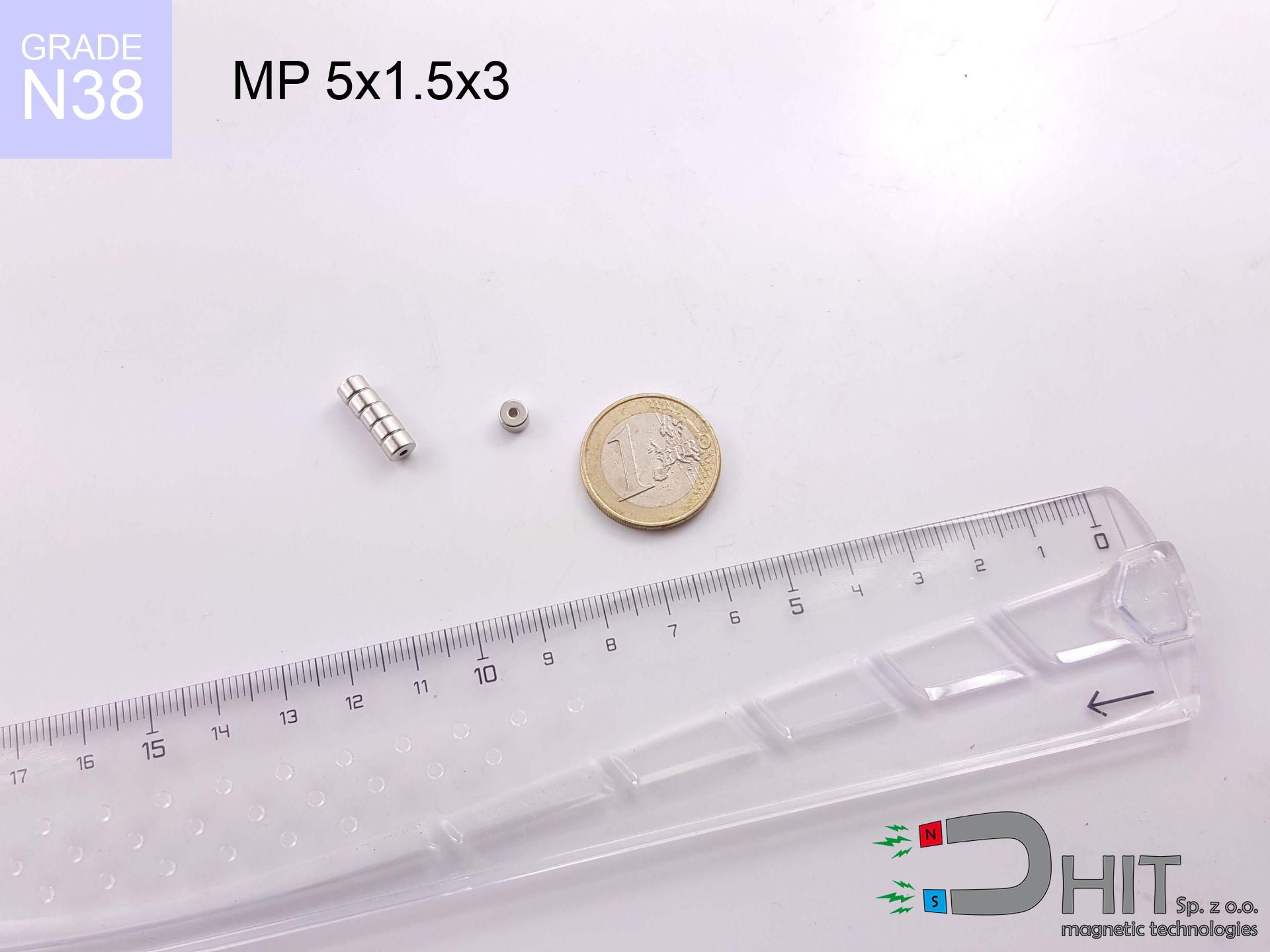
MP 5x1.5x3 / N38 - ring magnet
ring magnet
Catalog no 030451
GTIN/EAN: 5906301812357
Diameter
5 mm [±0,1 mm]
internal diameter Ø
1.5 mm [±0,1 mm]
Height
3 mm [±0,1 mm]
Weight
0.4 g
Magnetization Direction
↑ axial
Load capacity
0.77 kg / 7.50 N
Magnetic Induction
475.16 mT / 4752 Gs
Coating
[NiCuNi] Nickel
0.344 ZŁ with VAT / pcs + price for transport
0.280 ZŁ net + 23% VAT / pcs
bulk discounts:
Need more?
Contact us by phone
+48 22 499 98 98
or let us know through
our online form
the contact page.
Weight and structure of a magnet can be reviewed with our
magnetic mass calculator.
Orders submitted before 14:00 will be dispatched today!
Technical - MP 5x1.5x3 / N38 - ring magnet
Specification / characteristics - MP 5x1.5x3 / N38 - ring magnet
| properties | values |
|---|---|
| Cat. no. | 030451 |
| GTIN/EAN | 5906301812357 |
| Production/Distribution | Dhit sp. z o.o. |
| Country of origin | Poland / China / Germany |
| Customs code | 85059029 |
| Diameter | 5 mm [±0,1 mm] |
| internal diameter Ø | 1.5 mm [±0,1 mm] |
| Height | 3 mm [±0,1 mm] |
| Weight | 0.4 g |
| Magnetization Direction | ↑ axial |
| Load capacity ~ ? | 0.77 kg / 7.50 N |
| Magnetic Induction ~ ? | 475.16 mT / 4752 Gs |
| Coating | [NiCuNi] Nickel |
| Manufacturing Tolerance | ±0.1 mm |
Magnetic properties of material N38
| properties | values | units |
|---|---|---|
| remenance Br [min. - max.] ? | 12.2-12.6 | kGs |
| remenance Br [min. - max.] ? | 1220-1260 | mT |
| coercivity bHc ? | 10.8-11.5 | kOe |
| coercivity bHc ? | 860-915 | kA/m |
| actual internal force iHc | ≥ 12 | kOe |
| actual internal force iHc | ≥ 955 | kA/m |
| energy density [min. - max.] ? | 36-38 | BH max MGOe |
| energy density [min. - max.] ? | 287-303 | BH max KJ/m |
| max. temperature ? | ≤ 80 | °C |
Physical properties of sintered neodymium magnets Nd2Fe14B at 20°C
| properties | values | units |
|---|---|---|
| Vickers hardness | ≥550 | Hv |
| Density | ≥7.4 | g/cm3 |
| Curie Temperature TC | 312 - 380 | °C |
| Curie Temperature TF | 593 - 716 | °F |
| Specific resistance | 150 | μΩ⋅cm |
| Bending strength | 250 | MPa |
| Compressive strength | 1000~1100 | MPa |
| Thermal expansion parallel (∥) to orientation (M) | (3-4) x 10-6 | °C-1 |
| Thermal expansion perpendicular (⊥) to orientation (M) | -(1-3) x 10-6 | °C-1 |
| Young's modulus | 1.7 x 10⁴ | kg/mm² |
Engineering simulation of the assembly - data
Presented values constitute the outcome of a mathematical calculation. Results rely on models for the material Nd2Fe14B. Actual conditions may deviate from the simulation results. Please consider these calculations as a reference point during assembly planning.
Table 1: Static pull force (pull vs gap) - characteristics
MP 5x1.5x3 / N38
| Distance (mm) | Induction (Gauss) / mT | Pull Force (kg/lbs/g/N) | Risk Status |
|---|---|---|---|
| 0 mm |
6157 Gs
615.7 mT
|
0.77 kg / 1.70 LBS
770.0 g / 7.6 N
|
safe |
| 1 mm |
3880 Gs
388.0 mT
|
0.31 kg / 0.67 LBS
305.8 g / 3.0 N
|
safe |
| 2 mm |
2310 Gs
231.0 mT
|
0.11 kg / 0.24 LBS
108.4 g / 1.1 N
|
safe |
| 3 mm |
1422 Gs
142.2 mT
|
0.04 kg / 0.09 LBS
41.0 g / 0.4 N
|
safe |
| 5 mm |
641 Gs
64.1 mT
|
0.01 kg / 0.02 LBS
8.3 g / 0.1 N
|
safe |
| 10 mm |
174 Gs
17.4 mT
|
0.00 kg / 0.00 LBS
0.6 g / 0.0 N
|
safe |
| 15 mm |
76 Gs
7.6 mT
|
0.00 kg / 0.00 LBS
0.1 g / 0.0 N
|
safe |
| 20 mm |
41 Gs
4.1 mT
|
0.00 kg / 0.00 LBS
0.0 g / 0.0 N
|
safe |
| 30 mm |
16 Gs
1.6 mT
|
0.00 kg / 0.00 LBS
0.0 g / 0.0 N
|
safe |
| 50 mm |
5 Gs
0.5 mT
|
0.00 kg / 0.00 LBS
0.0 g / 0.0 N
|
safe |
Table 2: Shear load (vertical surface)
MP 5x1.5x3 / N38
| Distance (mm) | Friction coefficient | Pull Force (kg/lbs/g/N) |
|---|---|---|
| 0 mm | Stal (~0.2) |
0.15 kg / 0.34 LBS
154.0 g / 1.5 N
|
| 1 mm | Stal (~0.2) |
0.06 kg / 0.14 LBS
62.0 g / 0.6 N
|
| 2 mm | Stal (~0.2) |
0.02 kg / 0.05 LBS
22.0 g / 0.2 N
|
| 3 mm | Stal (~0.2) |
0.01 kg / 0.02 LBS
8.0 g / 0.1 N
|
| 5 mm | Stal (~0.2) |
0.00 kg / 0.00 LBS
2.0 g / 0.0 N
|
| 10 mm | Stal (~0.2) |
0.00 kg / 0.00 LBS
0.0 g / 0.0 N
|
| 15 mm | Stal (~0.2) |
0.00 kg / 0.00 LBS
0.0 g / 0.0 N
|
| 20 mm | Stal (~0.2) |
0.00 kg / 0.00 LBS
0.0 g / 0.0 N
|
| 30 mm | Stal (~0.2) |
0.00 kg / 0.00 LBS
0.0 g / 0.0 N
|
| 50 mm | Stal (~0.2) |
0.00 kg / 0.00 LBS
0.0 g / 0.0 N
|
Table 3: Vertical assembly (shearing) - vertical pull
MP 5x1.5x3 / N38
| Surface type | Friction coefficient / % Mocy | Max load (kg/lbs/g/N) |
|---|---|---|
| Raw steel |
µ = 0.3
30% Nominalnej Siły
|
0.23 kg / 0.51 LBS
231.0 g / 2.3 N
|
| Painted steel (standard) |
µ = 0.2
20% Nominalnej Siły
|
0.15 kg / 0.34 LBS
154.0 g / 1.5 N
|
| Oily/slippery steel |
µ = 0.1
10% Nominalnej Siły
|
0.08 kg / 0.17 LBS
77.0 g / 0.8 N
|
| Magnet with anti-slip rubber |
µ = 0.5
50% Nominalnej Siły
|
0.39 kg / 0.85 LBS
385.0 g / 3.8 N
|
Table 4: Material efficiency (substrate influence) - power losses
MP 5x1.5x3 / N38
| Steel thickness (mm) | % power | Real pull force (kg/lbs/g/N) |
|---|---|---|
| 0.5 mm |
|
0.08 kg / 0.17 LBS
77.0 g / 0.8 N
|
| 1 mm |
|
0.19 kg / 0.42 LBS
192.5 g / 1.9 N
|
| 2 mm |
|
0.39 kg / 0.85 LBS
385.0 g / 3.8 N
|
| 3 mm |
|
0.58 kg / 1.27 LBS
577.5 g / 5.7 N
|
| 5 mm |
|
0.77 kg / 1.70 LBS
770.0 g / 7.6 N
|
| 10 mm |
|
0.77 kg / 1.70 LBS
770.0 g / 7.6 N
|
| 11 mm |
|
0.77 kg / 1.70 LBS
770.0 g / 7.6 N
|
| 12 mm |
|
0.77 kg / 1.70 LBS
770.0 g / 7.6 N
|
Table 5: Thermal stability (stability) - thermal limit
MP 5x1.5x3 / N38
| Ambient temp. (°C) | Power loss | Remaining pull (kg/lbs/g/N) | Status |
|---|---|---|---|
| 20 °C | 0.0% |
0.77 kg / 1.70 LBS
770.0 g / 7.6 N
|
OK |
| 40 °C | -2.2% |
0.75 kg / 1.66 LBS
753.1 g / 7.4 N
|
OK |
| 60 °C | -4.4% |
0.74 kg / 1.62 LBS
736.1 g / 7.2 N
|
OK |
| 80 °C | -6.6% |
0.72 kg / 1.59 LBS
719.2 g / 7.1 N
|
|
| 100 °C | -28.8% |
0.55 kg / 1.21 LBS
548.2 g / 5.4 N
|
Table 6: Magnet-Magnet interaction (repulsion) - field range
MP 5x1.5x3 / N38
| Gap (mm) | Attraction (kg/lbs) (N-S) | Lateral Force (kg/lbs/g/N) | Repulsion (kg/lbs) (N-N) |
|---|---|---|---|
| 0 mm |
2.50 kg / 5.50 LBS
6 171 Gs
|
0.37 kg / 0.83 LBS
374 g / 3.7 N
|
N/A |
| 1 mm |
1.62 kg / 3.58 LBS
9 932 Gs
|
0.24 kg / 0.54 LBS
244 g / 2.4 N
|
1.46 kg / 3.22 LBS
~0 Gs
|
| 2 mm |
0.99 kg / 2.19 LBS
7 760 Gs
|
0.15 kg / 0.33 LBS
149 g / 1.5 N
|
0.89 kg / 1.97 LBS
~0 Gs
|
| 3 mm |
0.59 kg / 1.30 LBS
5 986 Gs
|
0.09 kg / 0.20 LBS
88 g / 0.9 N
|
0.53 kg / 1.17 LBS
~0 Gs
|
| 5 mm |
0.21 kg / 0.47 LBS
3 600 Gs
|
0.03 kg / 0.07 LBS
32 g / 0.3 N
|
0.19 kg / 0.42 LBS
~0 Gs
|
| 10 mm |
0.03 kg / 0.06 LBS
1 281 Gs
|
0.00 kg / 0.01 LBS
4 g / 0.0 N
|
0.02 kg / 0.05 LBS
~0 Gs
|
| 20 mm |
0.00 kg / 0.00 LBS
349 Gs
|
0.00 kg / 0.00 LBS
0 g / 0.0 N
|
0.00 kg / 0.00 LBS
~0 Gs
|
| 50 mm |
0.00 kg / 0.00 LBS
50 Gs
|
0.00 kg / 0.00 LBS
0 g / 0.0 N
|
0.00 kg / 0.00 LBS
~0 Gs
|
| 60 mm |
0.00 kg / 0.00 LBS
33 Gs
|
0.00 kg / 0.00 LBS
0 g / 0.0 N
|
0.00 kg / 0.00 LBS
~0 Gs
|
| 70 mm |
0.00 kg / 0.00 LBS
23 Gs
|
0.00 kg / 0.00 LBS
0 g / 0.0 N
|
0.00 kg / 0.00 LBS
~0 Gs
|
| 80 mm |
0.00 kg / 0.00 LBS
17 Gs
|
0.00 kg / 0.00 LBS
0 g / 0.0 N
|
0.00 kg / 0.00 LBS
~0 Gs
|
| 90 mm |
0.00 kg / 0.00 LBS
13 Gs
|
0.00 kg / 0.00 LBS
0 g / 0.0 N
|
0.00 kg / 0.00 LBS
~0 Gs
|
| 100 mm |
0.00 kg / 0.00 LBS
10 Gs
|
0.00 kg / 0.00 LBS
0 g / 0.0 N
|
0.00 kg / 0.00 LBS
~0 Gs
|
Table 7: Hazards (implants) - warnings
MP 5x1.5x3 / N38
| Object / Device | Limit (Gauss) / mT | Safe distance |
|---|---|---|
| Pacemaker | 5 Gs (0.5 mT) | 5.0 cm |
| Hearing aid | 10 Gs (1.0 mT) | 4.0 cm |
| Mechanical watch | 20 Gs (2.0 mT) | 3.0 cm |
| Mobile device | 40 Gs (4.0 mT) | 2.5 cm |
| Car key | 50 Gs (5.0 mT) | 2.0 cm |
| Payment card | 400 Gs (40.0 mT) | 1.0 cm |
| HDD hard drive | 600 Gs (60.0 mT) | 1.0 cm |
Table 8: Dynamics (kinetic energy) - warning
MP 5x1.5x3 / N38
| Start from (mm) | Speed (km/h) | Energy (J) | Predicted outcome |
|---|---|---|---|
| 10 mm |
44.27 km/h
(12.30 m/s)
|
0.03 J | |
| 30 mm |
76.64 km/h
(21.29 m/s)
|
0.09 J | |
| 50 mm |
98.94 km/h
(27.48 m/s)
|
0.15 J | |
| 100 mm |
139.93 km/h
(38.87 m/s)
|
0.30 J |
Table 9: Surface protection spec
MP 5x1.5x3 / N38
| Technical parameter | Value / Description |
|---|---|
| Coating type | [NiCuNi] Nickel |
| Layer structure | Nickel - Copper - Nickel |
| Layer thickness | 10-20 µm |
| Salt spray test (SST) ? | 24 h |
| Recommended environment | Indoors only (dry) |
Table 10: Electrical data (Pc)
MP 5x1.5x3 / N38
| Parameter | Value | SI Unit / Description |
|---|---|---|
| Magnetic Flux | 811 Mx | 8.1 µWb |
| Pc Coefficient | 1.66 | High (Stable) |
Table 11: Physics of underwater searching
MP 5x1.5x3 / N38
| Environment | Effective steel pull | Effect |
|---|---|---|
| Air (land) | 0.77 kg | Standard |
| Water (riverbed) |
0.88 kg
(+0.11 kg buoyancy gain)
|
+14.5% |
1. Sliding resistance
*Caution: On a vertical wall, the magnet retains merely ~20% of its nominal pull.
2. Plate thickness effect
*Thin steel (e.g. 0.5mm PC case) severely weakens the holding force.
3. Heat tolerance
*For N38 material, the max working temp is 80°C.
4. Demagnetization curve and operating point (B-H)
chart generated for the permeance coefficient Pc (Permeance Coefficient) = 1.66
The chart above illustrates the magnetic characteristics of the material within the second quadrant of the hysteresis loop. The solid red line represents the demagnetization curve (material potential), while the dashed blue line is the load line based on the magnet's geometry. The Pc (Permeance Coefficient), also known as the load line slope, is a dimensionless value that describes the relationship between the magnet's shape and its magnetic stability. The intersection of these two lines (the black dot) is the operating point — it determines the actual magnetic flux density generated by the magnet in this specific configuration. A higher Pc value means the magnet is more 'slender' (tall relative to its area), resulting in a higher operating point and better resistance to irreversible demagnetization caused by external fields or temperature. A value of 0.42 is relatively low (typical for flat magnets), meaning the operating point is closer to the 'knee' of the curve — caution is advised when operating at temperatures near the maximum limit to avoid strength loss.
Material specification
| iron (Fe) | 64% – 68% |
| neodymium (Nd) | 29% – 32% |
| boron (B) | 1.1% – 1.2% |
| dysprosium (Dy) | 0.5% – 2.0% |
| coating (Ni-Cu-Ni) | < 0.05% |
Environmental data
| recyclability (EoL) | 100% |
| recycled raw materials | ~10% (pre-cons) |
| carbon footprint | low / zredukowany |
| waste code (EWC) | 16 02 16 |
View more deals
![UMH 42x9x46 [M6] / N38 - magnetic holder with hook](https://cdn3.dhit.pl/graphics/products/umh-42x9x46-m6-vat.jpg "UMH 42x9x46 [M6] / N38 - magnetic holder with hook")


Advantages and disadvantages of rare earth magnets.
Strengths
- They have stable power, and over nearly 10 years their performance decreases symbolically – ~1% (in testing),
- They retain their magnetic properties even under close interference source,
- In other words, due to the glossy surface of gold, the element looks attractive,
- The surface of neodymium magnets generates a powerful magnetic field – this is one of their assets,
- Thanks to resistance to high temperature, they are capable of working (depending on the shape) even at temperatures up to 230°C and higher...
- Possibility of accurate forming as well as optimizing to specific conditions,
- Wide application in high-tech industry – they serve a role in mass storage devices, brushless drives, diagnostic systems, as well as technologically advanced constructions.
- Compactness – despite small sizes they generate large force, making them ideal for precision applications
Limitations
- To avoid cracks upon strong impacts, we suggest using special steel holders. Such a solution protects the magnet and simultaneously increases its durability.
- Neodymium magnets lose power when exposed to high temperatures. After reaching 80°C, many of them experience permanent weakening of power (a factor is the shape and dimensions of the magnet). We offer magnets specially adapted to work at temperatures up to 230°C marked [AH], which are extremely resistant to heat
- Due to the susceptibility of magnets to corrosion in a humid environment, we recommend using waterproof magnets made of rubber, plastic or other material stable to moisture, when using outdoors
- Due to limitations in producing nuts and complex shapes in magnets, we recommend using a housing - magnetic mechanism.
- Health risk related to microscopic parts of magnets can be dangerous, when accidentally swallowed, which becomes key in the context of child safety. It is also worth noting that tiny parts of these products can complicate diagnosis medical in case of swallowing.
- Due to complex production process, their price is relatively high,
Pull force analysis
Breakaway strength of the magnet in ideal conditions – what it depends on?
- on a base made of structural steel, effectively closing the magnetic field
- whose transverse dimension is min. 10 mm
- with an polished contact surface
- under conditions of gap-free contact (surface-to-surface)
- under axial force vector (90-degree angle)
- at ambient temperature approx. 20 degrees Celsius
Practical aspects of lifting capacity – factors
- Distance – existence of foreign body (paint, tape, air) acts as an insulator, which reduces power rapidly (even by 50% at 0.5 mm).
- Direction of force – highest force is obtained only during perpendicular pulling. The force required to slide of the magnet along the surface is usually several times lower (approx. 1/5 of the lifting capacity).
- Substrate thickness – to utilize 100% power, the steel must be sufficiently thick. Paper-thin metal restricts the lifting capacity (the magnet "punches through" it).
- Material composition – not every steel reacts the same. Alloy additives worsen the interaction with the magnet.
- Surface finish – ideal contact is possible only on polished steel. Any scratches and bumps reduce the real contact area, weakening the magnet.
- Temperature influence – hot environment weakens pulling force. Exceeding the limit temperature can permanently damage the magnet.
Lifting capacity was measured with the use of a polished steel plate of optimal thickness (min. 20 mm), under perpendicular pulling force, in contrast under attempts to slide the magnet the load capacity is reduced by as much as 5 times. Additionally, even a slight gap between the magnet’s surface and the plate lowers the holding force.
Safety rules for work with NdFeB magnets
Risk of cracking
Despite metallic appearance, neodymium is delicate and cannot withstand shocks. Do not hit, as the magnet may shatter into hazardous fragments.
Do not overheat magnets
Control the heat. Exposing the magnet to high heat will permanently weaken its magnetic structure and strength.
Do not give to children
Always store magnets out of reach of children. Ingestion danger is high, and the consequences of magnets clamping inside the body are tragic.
Machining danger
Mechanical processing of neodymium magnets poses a fire hazard. Magnetic powder reacts violently with oxygen and is difficult to extinguish.
Nickel allergy
Allergy Notice: The Ni-Cu-Ni coating contains nickel. If an allergic reaction happens, immediately stop working with magnets and use protective gear.
Warning for heart patients
Warning for patients: Strong magnetic fields disrupt electronics. Keep minimum 30 cm distance or request help to handle the magnets.
Magnetic interference
Be aware: rare earth magnets generate a field that disrupts sensitive sensors. Keep a separation from your mobile, tablet, and navigation systems.
Safe distance
Intense magnetic fields can destroy records on credit cards, hard drives, and other magnetic media. Stay away of at least 10 cm.
Handling rules
Be careful. Neodymium magnets act from a distance and snap with massive power, often faster than you can move away.
Crushing force
Risk of injury: The attraction force is so immense that it can result in hematomas, pinching, and broken bones. Use thick gloves.
Tabela kosztu i czasu dostawy
Płatność przed wysyłką:

GLS kurier
Przesyłka będzie u Ciebie za 2-3 dni
14.99 ZŁ

InPost Paczkomaty 24/7
Przesyłka będzie u Ciebie za 1-2 dni
12.30 ZŁ
Płatność przy odbiorze (pobranie):
GLS kurier
Przesyłka będzie u Ciebie za 1-2 dni
23.00 ZŁ
Rate the product
Your rating