
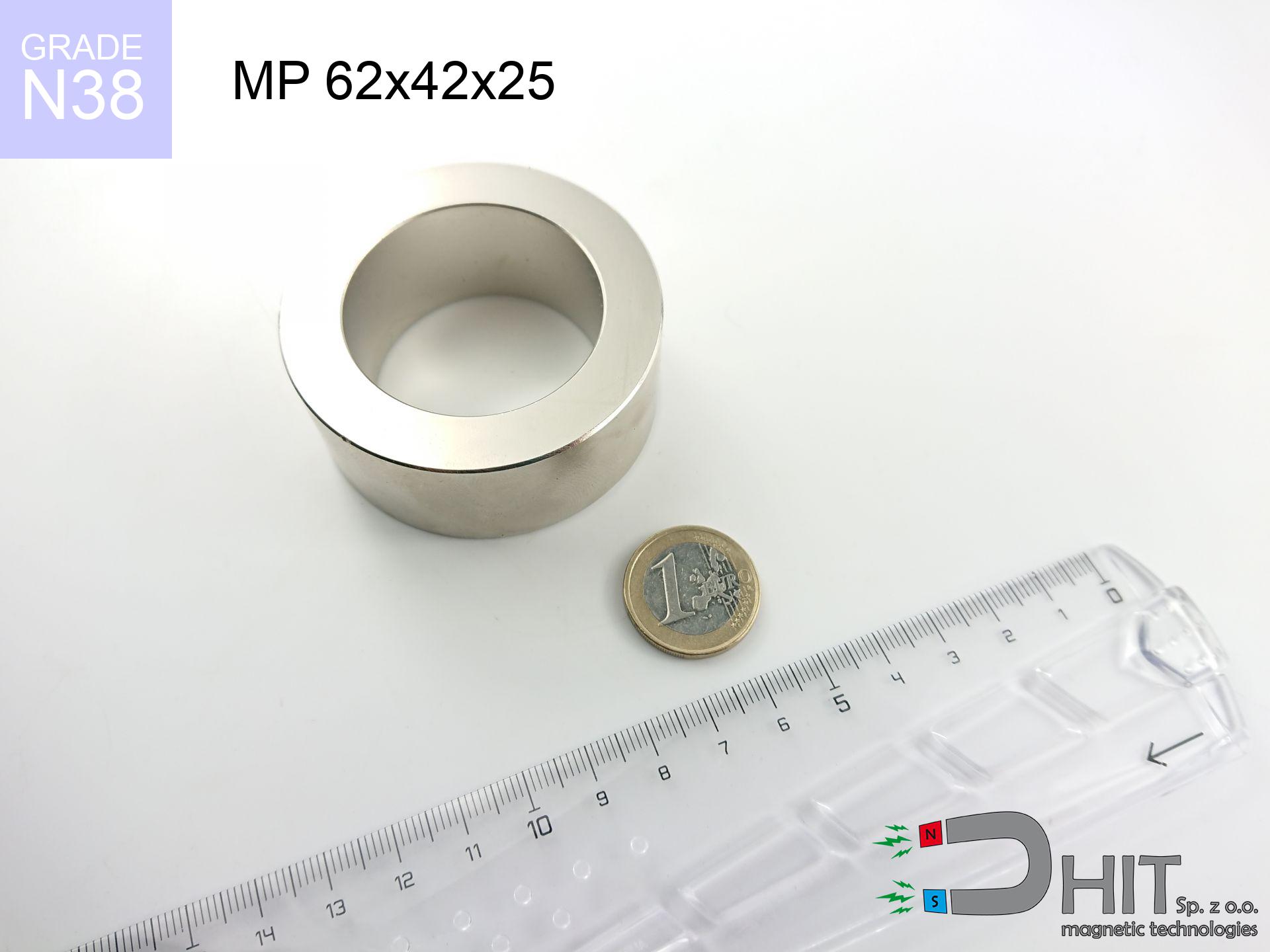
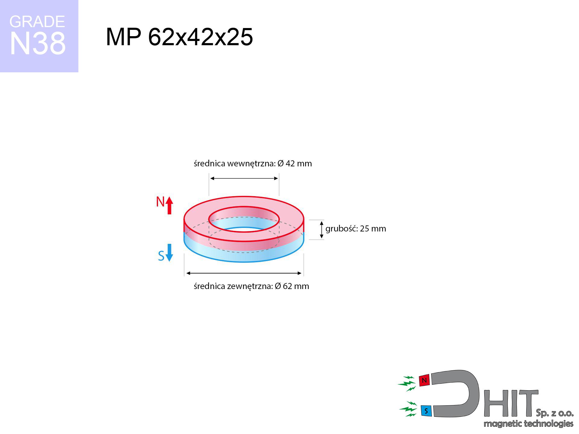
MP 62x42x25 / N38 - ring magnet
ring magnet
Catalog no 030205
GTIN/EAN: 5906301812227
- Diameter
- 62 mm [±0,1 mm]
- internal diameter Ø
- 42 mm [±0,1 mm]
- Height
- 25 mm [±0,1 mm]
- Weight
- 306.31 g
- Magnetization Direction
- ↑ axial
- Coating
- [NiCuNi] Nickel
165.00 zł with VAT / pcs + price for transport
134.15 zł net + 23% VAT / pcs
bulk discounts:
Need more?Engineering report for this magnet
Full PDF analysis: pull and shear force, effect of distance, temperature and plate thickness, safety distances and the demagnetization curve.
Pick up the phone and ask
+48 888 99 98 98
alternatively get in touch using
request form
the contact form page.
Lifting power along with shape of a neodymium magnet can be checked with our
online calculation tool.
Order by 14:00 and we’ll ship today!
Detailed specification - MP 62x42x25 / N38 - ring magnet
Specification / characteristics - MP 62x42x25 / N38 - ring magnet
| properties | values |
|---|---|
| Cat. no. | 030205 |
| GTIN/EAN | 5906301812227 |
| Production/Distribution | Dhit sp. z o.o. |
| Country of origin | Poland / China / Germany |
| Customs code | 85059029 |
| Diameter | 62 mm [±0,1 mm] |
| internal diameter Ø | 42 mm [±0,1 mm] |
| Height | 25 mm [±0,1 mm] |
| Weight | 306.31 g |
| Magnetization Direction | ↑ axial |
| Load capacity ~ ? | 58.67 kg / 575.60 N |
| Magnetic Induction ~ ? | 389.14 mT / 3891 Gs |
| Coating | [NiCuNi] Nickel |
| Manufacturing Tolerance | ±0.1 mm |
Magnetic properties of material N38
| properties | values | units |
|---|---|---|
| remenance Br [min. - max.] ? | 12.2-12.6 | kGs |
| remenance Br [min. - max.] ? | 1220-1260 | mT |
| coercivity bHc ? | 10.8-11.5 | kOe |
| coercivity bHc ? | 860-915 | kA/m |
| actual internal force iHc | ≥ 12 | kOe |
| actual internal force iHc | ≥ 955 | kA/m |
| energy density [min. - max.] ? | 36-38 | BH max MGOe |
| energy density [min. - max.] ? | 287-303 | BH max KJ/m |
| max. temperature ? | ≤ 80 | °C |
Physical properties of sintered neodymium magnets Nd2Fe14B at 20°C
| properties | values | units |
|---|---|---|
| Vickers hardness | ≥550 | Hv |
| Density | ≥7.4 | g/cm3 |
| Curie Temperature TC | 312 - 380 | °C |
| Curie Temperature TF | 593 - 716 | °F |
| Specific resistance | 150 | μΩ⋅cm |
| Bending strength | 250 | MPa |
| Compressive strength | 1000~1100 | MPa |
| Thermal expansion parallel (∥) to orientation (M) | (3-4) x 10-6 | °C-1 |
| Thermal expansion perpendicular (⊥) to orientation (M) | -(1-3) x 10-6 | °C-1 |
| Young's modulus | 1.7 x 10⁴ | kg/mm² |
Physical simulation of the assembly - data
Presented values represent the outcome of a mathematical simulation. Values rely on algorithms for the material Nd2Fe14B. Actual conditions might slightly differ from theoretical values. Treat these calculations as a reference point for designers.
Table 1: Static force (force vs distance) - power drop
MP 62x42x25 / N38
| Distance (mm) | Induction (Gauss) / mT | Pull Force (kg/lbs/g/N) | Risk Status |
|---|---|---|---|
| 0 mm |
4472 Gs
447.2 mT
|
58.67 kg / 129.35 lbs
58670.0 g / 575.6 N
|
critical level |
| 1 mm |
4338 Gs
433.8 mT
|
55.21 kg / 121.72 lbs
55213.2 g / 541.6 N
|
critical level |
| 2 mm |
4201 Gs
420.1 mT
|
51.77 kg / 114.13 lbs
51768.5 g / 507.8 N
|
critical level |
| 3 mm |
4061 Gs
406.1 mT
|
48.39 kg / 106.69 lbs
48394.9 g / 474.8 N
|
critical level |
| 5 mm |
3781 Gs
378.1 mT
|
41.94 kg / 92.47 lbs
41942.4 g / 411.5 N
|
critical level |
| 10 mm |
3097 Gs
309.7 mT
|
28.15 kg / 62.06 lbs
28148.0 g / 276.1 N
|
critical level |
| 15 mm |
2485 Gs
248.5 mT
|
18.12 kg / 39.94 lbs
18118.5 g / 177.7 N
|
critical level |
| 20 mm |
1972 Gs
197.2 mT
|
11.41 kg / 25.16 lbs
11412.7 g / 112.0 N
|
critical level |
| 30 mm |
1239 Gs
123.9 mT
|
4.51 kg / 9.93 lbs
4505.2 g / 44.2 N
|
medium risk |
| 50 mm |
533 Gs
53.3 mT
|
0.83 kg / 1.84 lbs
832.4 g / 8.2 N
|
low risk |
Table 2: Shear capacity (wall)
MP 62x42x25 / N38
| Distance (mm) | Friction coefficient | Pull Force (kg/lbs/g/N) |
|---|---|---|
| 0 mm | Stal (~0.2) |
11.73 kg / 25.87 lbs
11734.0 g / 115.1 N
|
| 1 mm | Stal (~0.2) |
11.04 kg / 24.34 lbs
11042.0 g / 108.3 N
|
| 2 mm | Stal (~0.2) |
10.35 kg / 22.83 lbs
10354.0 g / 101.6 N
|
| 3 mm | Stal (~0.2) |
9.68 kg / 21.34 lbs
9678.0 g / 94.9 N
|
| 5 mm | Stal (~0.2) |
8.39 kg / 18.49 lbs
8388.0 g / 82.3 N
|
| 10 mm | Stal (~0.2) |
5.63 kg / 12.41 lbs
5630.0 g / 55.2 N
|
| 15 mm | Stal (~0.2) |
3.62 kg / 7.99 lbs
3624.0 g / 35.6 N
|
| 20 mm | Stal (~0.2) |
2.28 kg / 5.03 lbs
2282.0 g / 22.4 N
|
| 30 mm | Stal (~0.2) |
0.90 kg / 1.99 lbs
902.0 g / 8.8 N
|
| 50 mm | Stal (~0.2) |
0.17 kg / 0.37 lbs
166.0 g / 1.6 N
|
Table 3: Wall mounting (shearing) - behavior on slippery surfaces
MP 62x42x25 / N38
| Surface type | Friction coefficient / % Mocy | Max load (kg/lbs/g/N) |
|---|---|---|
| Raw steel |
µ = 0.3
30% Nominalnej Siły
|
17.60 kg / 38.80 lbs
17601.0 g / 172.7 N
|
| Painted steel (standard) |
µ = 0.2
20% Nominalnej Siły
|
11.73 kg / 25.87 lbs
11734.0 g / 115.1 N
|
| Oily/slippery steel |
µ = 0.1
10% Nominalnej Siły
|
5.87 kg / 12.93 lbs
5867.0 g / 57.6 N
|
| Magnet with anti-slip rubber |
µ = 0.5
50% Nominalnej Siły
|
29.34 kg / 64.67 lbs
29335.0 g / 287.8 N
|
Table 4: Steel thickness (substrate influence) - sheet metal selection
MP 62x42x25 / N38
| Steel thickness (mm) | % power | Real pull force (kg/lbs/g/N) |
|---|---|---|
| 0.5 mm |
|
1.96 kg / 4.31 lbs
1955.7 g / 19.2 N
|
| 1 mm |
|
4.89 kg / 10.78 lbs
4889.2 g / 48.0 N
|
| 2 mm |
|
9.78 kg / 21.56 lbs
9778.3 g / 95.9 N
|
| 3 mm |
|
14.67 kg / 32.34 lbs
14667.5 g / 143.9 N
|
| 5 mm |
|
24.45 kg / 53.89 lbs
24445.8 g / 239.8 N
|
| 10 mm |
|
48.89 kg / 107.79 lbs
48891.7 g / 479.6 N
|
| 11 mm |
|
53.78 kg / 118.57 lbs
53780.8 g / 527.6 N
|
| 12 mm |
|
58.67 kg / 129.35 lbs
58670.0 g / 575.6 N
|
Table 5: Working in heat (stability) - resistance threshold
MP 62x42x25 / N38
| Ambient temp. (°C) | Power loss | Remaining pull (kg/lbs/g/N) | Status |
|---|---|---|---|
| 20 °C | 0.0% |
58.67 kg / 129.35 lbs
58670.0 g / 575.6 N
|
OK |
| 40 °C | -2.2% |
57.38 kg / 126.50 lbs
57379.3 g / 562.9 N
|
OK |
| 60 °C | -4.4% |
56.09 kg / 123.65 lbs
56088.5 g / 550.2 N
|
OK |
| 80 °C | -6.6% |
54.80 kg / 120.81 lbs
54797.8 g / 537.6 N
|
|
| 100 °C | -28.8% |
41.77 kg / 92.09 lbs
41773.0 g / 409.8 N
|
Table 6: Magnet-Magnet interaction (attraction) - field range
MP 62x42x25 / N38
| Gap (mm) | Attraction (kg/lbs) (N-S) | Shear Strength (kg/lbs/g/N) | Repulsion (kg/lbs) (N-N) |
|---|---|---|---|
| 0 mm |
264.93 kg / 584.07 lbs
5 588 Gs
|
39.74 kg / 87.61 lbs
39740 g / 389.8 N
|
N/A |
| 1 mm |
257.19 kg / 567.00 lbs
8 812 Gs
|
38.58 kg / 85.05 lbs
38578 g / 378.4 N
|
231.47 kg / 510.30 lbs
~0 Gs
|
| 2 mm |
249.32 kg / 549.66 lbs
8 676 Gs
|
37.40 kg / 82.45 lbs
37398 g / 366.9 N
|
224.39 kg / 494.69 lbs
~0 Gs
|
| 3 mm |
241.51 kg / 532.44 lbs
8 539 Gs
|
36.23 kg / 79.87 lbs
36227 g / 355.4 N
|
217.36 kg / 479.19 lbs
~0 Gs
|
| 5 mm |
226.10 kg / 498.47 lbs
8 262 Gs
|
33.92 kg / 74.77 lbs
33915 g / 332.7 N
|
203.49 kg / 448.62 lbs
~0 Gs
|
| 10 mm |
189.40 kg / 417.55 lbs
7 562 Gs
|
28.41 kg / 62.63 lbs
28409 g / 278.7 N
|
170.46 kg / 375.79 lbs
~0 Gs
|
| 20 mm |
127.11 kg / 280.22 lbs
6 195 Gs
|
19.07 kg / 42.03 lbs
19066 g / 187.0 N
|
114.40 kg / 252.20 lbs
~0 Gs
|
| 50 mm |
32.28 kg / 71.17 lbs
3 122 Gs
|
4.84 kg / 10.68 lbs
4843 g / 47.5 N
|
29.06 kg / 64.06 lbs
~0 Gs
|
| 60 mm |
20.34 kg / 44.85 lbs
2 478 Gs
|
3.05 kg / 6.73 lbs
3052 g / 29.9 N
|
18.31 kg / 40.36 lbs
~0 Gs
|
| 70 mm |
12.99 kg / 28.63 lbs
1 980 Gs
|
1.95 kg / 4.29 lbs
1948 g / 19.1 N
|
11.69 kg / 25.77 lbs
~0 Gs
|
| 80 mm |
8.43 kg / 18.59 lbs
1 595 Gs
|
1.26 kg / 2.79 lbs
1265 g / 12.4 N
|
7.59 kg / 16.73 lbs
~0 Gs
|
| 90 mm |
5.58 kg / 12.29 lbs
1 298 Gs
|
0.84 kg / 1.84 lbs
836 g / 8.2 N
|
5.02 kg / 11.06 lbs
~0 Gs
|
| 100 mm |
3.76 kg / 8.29 lbs
1 065 Gs
|
0.56 kg / 1.24 lbs
564 g / 5.5 N
|
3.38 kg / 7.46 lbs
~0 Gs
|
Table 7: Safety (HSE) (implants) - precautionary measures
MP 62x42x25 / N38
| Object / Device | Limit (Gauss) / mT | Safe distance |
|---|---|---|
| Pacemaker | 5 Gs (0.5 mT) | 32.5 cm |
| Hearing aid | 10 Gs (1.0 mT) | 25.5 cm |
| Timepiece | 20 Gs (2.0 mT) | 20.0 cm |
| Mobile device | 40 Gs (4.0 mT) | 15.5 cm |
| Car key | 50 Gs (5.0 mT) | 14.0 cm |
| Payment card | 400 Gs (40.0 mT) | 6.0 cm |
| HDD hard drive | 600 Gs (60.0 mT) | 5.0 cm |
Table 8: Dynamics (kinetic energy) - collision effects
MP 62x42x25 / N38
| Start from (mm) | Speed (km/h) | Energy (J) | Predicted outcome |
|---|---|---|---|
| 10 mm |
18.77 km/h
(5.21 m/s)
|
4.16 J | |
| 30 mm |
23.85 km/h
(6.63 m/s)
|
6.72 J | |
| 50 mm |
24.58 km/h
(6.83 m/s)
|
7.14 J | |
| 100 mm |
24.78 km/h
(6.88 m/s)
|
7.26 J |
Table 9: Surface protection spec
MP 62x42x25 / N38
| Technical parameter | Value / Description |
|---|---|
| Coating type | [NiCuNi] Nickel |
| Layer structure | Nickel - Copper - Nickel |
| Layer thickness | 10-20 µm |
| Salt spray test (SST) ? | 24 h |
| Recommended environment | Indoors only (dry) |
Table 10: Construction data (Pc)
MP 62x42x25 / N38
| Parameter | Value | SI Unit / Description |
|---|---|---|
| Magnetic Flux | 100 906 Mx | 1009.1 µWb |
| Pc Coefficient | 0.64 | High (Stable) |
Table 11: Physics of underwater searching
MP 62x42x25 / N38
| Environment | Effective steel pull | Effect |
|---|---|---|
| Air (land) | 58.67 kg | Standard |
| Water (riverbed) |
67.18 kg
(+8.51 kg buoyancy gain)
|
+14.5% |
1. Shear force
*Caution: On a vertical surface, the magnet holds just ~20% of its nominal pull.
2. Steel saturation
*Thin metal sheet (e.g. computer case) severely weakens the holding force.
3. Thermal stability
*For N38 grade, the max working temp is 80°C.
4. Demagnetization curve and operating point (B-H)
chart generated for the permeance coefficient Pc (Permeance Coefficient) = 0.64
The chart above illustrates the magnetic characteristics of the material within the second quadrant of the hysteresis loop. The solid red line represents the demagnetization curve (material potential), while the dashed blue line is the load line based on the magnet's geometry. The Pc (Permeance Coefficient), also known as the load line slope, is a dimensionless value that describes the relationship between the magnet's shape and its magnetic stability. The intersection of these two lines (the black dot) is the operating point — it determines the actual magnetic flux density generated by the magnet in this specific configuration. A higher Pc value means the magnet is more 'slender' (tall relative to its area), resulting in a higher operating point and better resistance to irreversible demagnetization caused by external fields or temperature. A value of 0.42 is relatively low (typical for flat magnets), meaning the operating point is closer to the 'knee' of the curve — caution is advised when operating at temperatures near the maximum limit to avoid strength loss.
Chemical composition
| iron (Fe) | 64% – 68% |
| neodymium (Nd) | 29% – 32% |
| boron (B) | 1.1% – 1.2% |
| dysprosium (Dy) | 0.5% – 2.0% |
| coating (Ni-Cu-Ni) | < 0.05% |
Ecology and recycling (GPSR)
| recyclability (EoL) | 100% |
| recycled raw materials | ~10% (pre-cons) |
| carbon footprint | low / zredukowany |
| waste code (EWC) | 16 02 16 |
Other products

![MPL 40x10x4x2[7/3.5] / N38 - lamellar magnet](https://cdn3.dhit.pl/graphics/products/mpl40x10x4x27-3.5-suw.jpg "MPL 40x10x4x2[7/3.5] / N38 - lamellar magnet")


Pros and cons of neodymium magnets.
Pros
- They virtually do not lose strength, because even after 10 years the performance loss is only ~1% (based on calculations),
- They are extremely resistant to demagnetization induced by external magnetic fields,
- By covering with a smooth coating of silver, the element presents an nice look,
- Magnetic induction on the working part of the magnet remains maximum,
- Neodymium magnets are characterized by very high magnetic induction on the magnet surface and can work (depending on the form) even at a temperature of 230°C or more...
- Thanks to freedom in designing and the capacity to customize to client solutions,
- Huge importance in high-tech industry – they serve a role in magnetic memories, electric motors, precision medical tools, as well as complex engineering applications.
- Relatively small size with high pulling force – neodymium magnets offer strong magnetic field in compact dimensions, which enables their usage in small systems
Cons
- They are prone to damage upon too strong impacts. To avoid cracks, it is worth protecting magnets using a steel holder. Such protection not only shields the magnet but also increases its resistance to damage
- Neodymium magnets decrease their force under the influence of heating. As soon as 80°C is exceeded, many of them start losing their force. Therefore, we recommend our special magnets marked [AH], which maintain durability even at temperatures up to 230°C
- Due to the susceptibility of magnets to corrosion in a humid environment, we advise using waterproof magnets made of rubber, plastic or other material immune to moisture, in case of application outdoors
- Limited ability of making nuts in the magnet and complicated forms - preferred is casing - magnet mounting.
- Health risk to health – tiny shards of magnets can be dangerous, if swallowed, which becomes key in the context of child health protection. Furthermore, small components of these devices can disrupt the diagnostic process medical in case of swallowing.
- Higher cost of purchase is one of the disadvantages compared to ceramic magnets, especially in budget applications
Holding force characteristics
Magnetic strength at its maximum – what contributes to it?
- on a block made of structural steel, optimally conducting the magnetic flux
- whose thickness is min. 10 mm
- with an ground contact surface
- without any clearance between the magnet and steel
- for force applied at a right angle (in the magnet axis)
- in neutral thermal conditions
Lifting capacity in real conditions – factors
- Clearance – existence of foreign body (rust, tape, gap) acts as an insulator, which reduces capacity steeply (even by 50% at 0.5 mm).
- Force direction – catalog parameter refers to pulling vertically. When attempting to slide, the magnet holds significantly lower power (often approx. 20-30% of nominal force).
- Substrate thickness – to utilize 100% power, the steel must be sufficiently thick. Thin sheet restricts the lifting capacity (the magnet "punches through" it).
- Material composition – different alloys reacts the same. High carbon content worsen the attraction effect.
- Surface structure – the more even the plate, the larger the contact zone and higher the lifting capacity. Unevenness creates an air distance.
- Temperature – temperature increase causes a temporary drop of force. It is worth remembering the thermal limit for a given model.
Lifting capacity testing was performed on a smooth plate of suitable thickness, under a perpendicular pulling force, however under attempts to slide the magnet the holding force is lower. Moreover, even a minimal clearance between the magnet’s surface and the plate lowers the lifting capacity.
Warnings
Skin irritation risks
Some people have a hypersensitivity to Ni, which is the common plating for NdFeB magnets. Frequent touching might lead to skin redness. We strongly advise use safety gloves.
Electronic devices
Equipment safety: Strong magnets can damage payment cards and sensitive devices (pacemakers, hearing aids, timepieces).
Bone fractures
Big blocks can break fingers in a fraction of a second. Never put your hand between two strong magnets.
Magnetic interference
A strong magnetic field interferes with the operation of magnetometers in phones and navigation systems. Maintain magnets near a device to avoid damaging the sensors.
Handling guide
Before use, check safety instructions. Uncontrolled attraction can break the magnet or hurt your hand. Think ahead.
Pacemakers
For implant holders: Strong magnetic fields disrupt medical devices. Maintain minimum 30 cm distance or ask another person to handle the magnets.
Material brittleness
Despite metallic appearance, the material is delicate and cannot withstand shocks. Do not hit, as the magnet may shatter into sharp, dangerous pieces.
Combustion hazard
Combustion risk: Rare earth powder is highly flammable. Avoid machining magnets in home conditions as this risks ignition.
Operating temperature
Avoid heat. Neodymium magnets are susceptible to temperature. If you require resistance above 80°C, inquire about special high-temperature series (H, SH, UH).
Danger to the youngest
Strictly store magnets away from children. Risk of swallowing is high, and the effects of magnets connecting inside the body are fatal.
Tabela kosztu i czasu dostawy
Płatność przed wysyłką:

GLS kurier
Przesyłka będzie u Ciebie za 2-3 dni
14.99 ZŁ

InPost Paczkomaty 24/7
Przesyłka będzie u Ciebie za 1-2 dni
12.30 ZŁ
Płatność przy odbiorze (pobranie):
GLS kurier
Przesyłka będzie u Ciebie za 1-2 dni
23.00 ZŁ
Rate the product
Your rating