
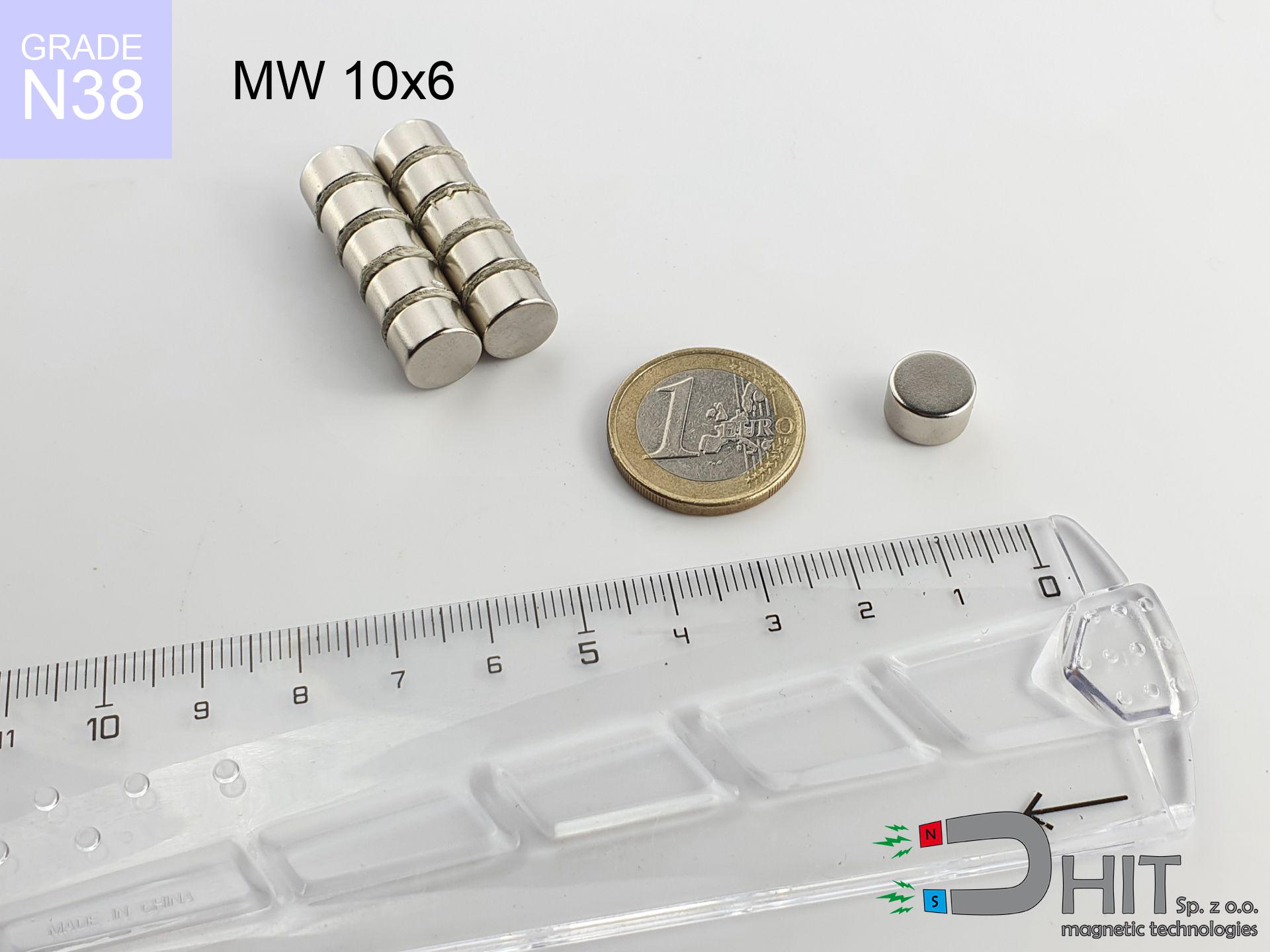
MW 10x6 / N38 - cylindrical magnet
cylindrical magnet
Catalog no 010012
GTIN/EAN: 5906301810117
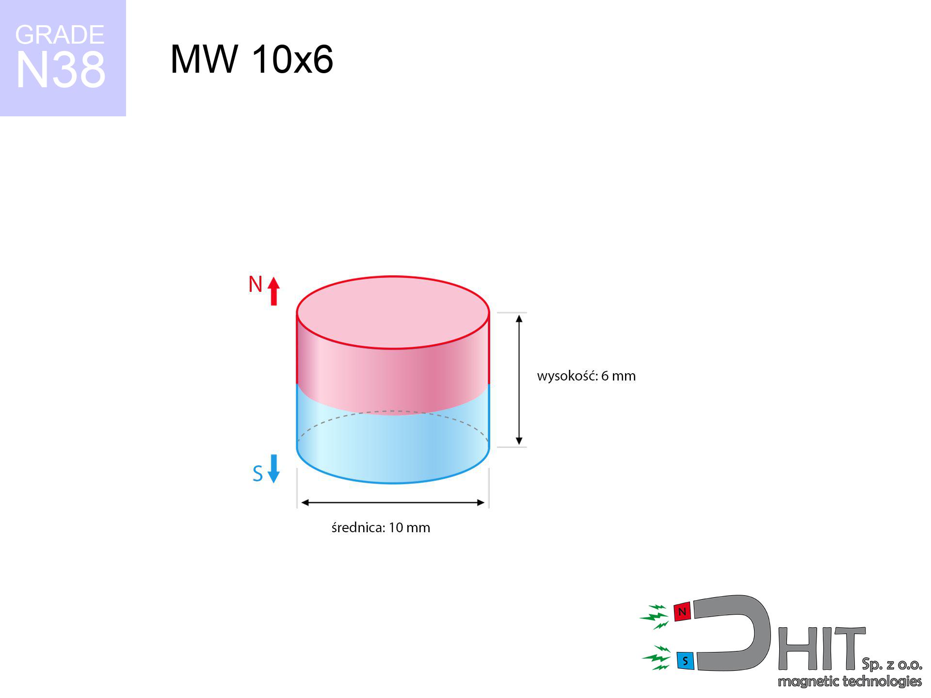
- Diameter Ø
- 10 mm [±0,1 mm]
- Height
- 6 mm [±0,1 mm]
- Weight
- 3.53 g
- Magnetization Direction
- ↑ axial
- Coating
- [NiCuNi] Nickel
1.045 zł with VAT / pcs + price for transport
0.850 zł net + 23% VAT / pcs
bulk discounts:
Need more?Engineering report for this magnet
Full PDF analysis: pull and shear force, effect of distance, temperature and plate thickness, safety distances and the demagnetization curve.
Call us now
+48 22 499 98 98
alternatively contact us via
form
the contact form page.
Strength as well as appearance of neodymium magnets can be analyzed on our
modular calculator.
Orders submitted before 14:00 will be dispatched today!
Technical - MW 10x6 / N38 - cylindrical magnet
Specification / characteristics - MW 10x6 / N38 - cylindrical magnet
| properties | values |
|---|---|
| Cat. no. | 010012 |
| GTIN/EAN | 5906301810117 |
| Production/Distribution | Dhit sp. z o.o. |
| Country of origin | Poland / China / Germany |
| Customs code | 85059029 |
| Diameter Ø | 10 mm [±0,1 mm] |
| Height | 6 mm [±0,1 mm] |
| Weight | 3.53 g |
| Magnetization Direction | ↑ axial |
| Load capacity ~ ? | 3.38 kg / 33.12 N |
| Magnetic Induction ~ ? | 475.73 mT / 4757 Gs |
| Coating | [NiCuNi] Nickel |
| Manufacturing Tolerance | ±0.1 mm |
Magnetic properties of material N38
| properties | values | units |
|---|---|---|
| remenance Br [min. - max.] ? | 12.2-12.6 | kGs |
| remenance Br [min. - max.] ? | 1220-1260 | mT |
| coercivity bHc ? | 10.8-11.5 | kOe |
| coercivity bHc ? | 860-915 | kA/m |
| actual internal force iHc | ≥ 12 | kOe |
| actual internal force iHc | ≥ 955 | kA/m |
| energy density [min. - max.] ? | 36-38 | BH max MGOe |
| energy density [min. - max.] ? | 287-303 | BH max KJ/m |
| max. temperature ? | ≤ 80 | °C |
Physical properties of sintered neodymium magnets Nd2Fe14B at 20°C
| properties | values | units |
|---|---|---|
| Vickers hardness | ≥550 | Hv |
| Density | ≥7.4 | g/cm3 |
| Curie Temperature TC | 312 - 380 | °C |
| Curie Temperature TF | 593 - 716 | °F |
| Specific resistance | 150 | μΩ⋅cm |
| Bending strength | 250 | MPa |
| Compressive strength | 1000~1100 | MPa |
| Thermal expansion parallel (∥) to orientation (M) | (3-4) x 10-6 | °C-1 |
| Thermal expansion perpendicular (⊥) to orientation (M) | -(1-3) x 10-6 | °C-1 |
| Young's modulus | 1.7 x 10⁴ | kg/mm² |
Engineering modeling of the product - report
Presented values constitute the direct effect of a physical simulation. Results are based on models for the class Nd2Fe14B. Operational parameters may deviate from the simulation results. Please consider these calculations as a supplementary guide during assembly planning.
Table 1: Static pull force (pull vs distance) - power drop
MW 10x6 / N38
| Distance (mm) | Induction (Gauss) / mT | Pull Force (kg/lbs/g/N) | Risk Status |
|---|---|---|---|
| 0 mm |
4754 Gs
475.4 mT
|
3.38 kg / 7.45 lbs
3380.0 g / 33.2 N
|
strong |
| 1 mm |
3829 Gs
382.9 mT
|
2.19 kg / 4.83 lbs
2193.1 g / 21.5 N
|
strong |
| 2 mm |
2955 Gs
295.5 mT
|
1.31 kg / 2.88 lbs
1306.0 g / 12.8 N
|
low risk |
| 3 mm |
2230 Gs
223.0 mT
|
0.74 kg / 1.64 lbs
743.7 g / 7.3 N
|
low risk |
| 5 mm |
1260 Gs
126.0 mT
|
0.24 kg / 0.52 lbs
237.5 g / 2.3 N
|
low risk |
| 10 mm |
372 Gs
37.2 mT
|
0.02 kg / 0.05 lbs
20.7 g / 0.2 N
|
low risk |
| 15 mm |
150 Gs
15.0 mT
|
0.00 kg / 0.01 lbs
3.3 g / 0.0 N
|
low risk |
| 20 mm |
74 Gs
7.4 mT
|
0.00 kg / 0.00 lbs
0.8 g / 0.0 N
|
low risk |
| 30 mm |
25 Gs
2.5 mT
|
0.00 kg / 0.00 lbs
0.1 g / 0.0 N
|
low risk |
| 50 mm |
6 Gs
0.6 mT
|
0.00 kg / 0.00 lbs
0.0 g / 0.0 N
|
low risk |
Table 2: Shear force (wall)
MW 10x6 / N38
| Distance (mm) | Friction coefficient | Pull Force (kg/lbs/g/N) |
|---|---|---|
| 0 mm | Stal (~0.2) |
0.68 kg / 1.49 lbs
676.0 g / 6.6 N
|
| 1 mm | Stal (~0.2) |
0.44 kg / 0.97 lbs
438.0 g / 4.3 N
|
| 2 mm | Stal (~0.2) |
0.26 kg / 0.58 lbs
262.0 g / 2.6 N
|
| 3 mm | Stal (~0.2) |
0.15 kg / 0.33 lbs
148.0 g / 1.5 N
|
| 5 mm | Stal (~0.2) |
0.05 kg / 0.11 lbs
48.0 g / 0.5 N
|
| 10 mm | Stal (~0.2) |
0.00 kg / 0.01 lbs
4.0 g / 0.0 N
|
| 15 mm | Stal (~0.2) |
0.00 kg / 0.00 lbs
0.0 g / 0.0 N
|
| 20 mm | Stal (~0.2) |
0.00 kg / 0.00 lbs
0.0 g / 0.0 N
|
| 30 mm | Stal (~0.2) |
0.00 kg / 0.00 lbs
0.0 g / 0.0 N
|
| 50 mm | Stal (~0.2) |
0.00 kg / 0.00 lbs
0.0 g / 0.0 N
|
Table 3: Wall mounting (shearing) - behavior on slippery surfaces
MW 10x6 / N38
| Surface type | Friction coefficient / % Mocy | Max load (kg/lbs/g/N) |
|---|---|---|
| Raw steel |
µ = 0.3
30% Nominalnej Siły
|
1.01 kg / 2.24 lbs
1014.0 g / 9.9 N
|
| Painted steel (standard) |
µ = 0.2
20% Nominalnej Siły
|
0.68 kg / 1.49 lbs
676.0 g / 6.6 N
|
| Oily/slippery steel |
µ = 0.1
10% Nominalnej Siły
|
0.34 kg / 0.75 lbs
338.0 g / 3.3 N
|
| Magnet with anti-slip rubber |
µ = 0.5
50% Nominalnej Siły
|
1.69 kg / 3.73 lbs
1690.0 g / 16.6 N
|
Table 4: Material efficiency (saturation) - sheet metal selection
MW 10x6 / N38
| Steel thickness (mm) | % power | Real pull force (kg/lbs/g/N) |
|---|---|---|
| 0.5 mm |
|
0.34 kg / 0.75 lbs
338.0 g / 3.3 N
|
| 1 mm |
|
0.85 kg / 1.86 lbs
845.0 g / 8.3 N
|
| 2 mm |
|
1.69 kg / 3.73 lbs
1690.0 g / 16.6 N
|
| 3 mm |
|
2.54 kg / 5.59 lbs
2535.0 g / 24.9 N
|
| 5 mm |
|
3.38 kg / 7.45 lbs
3380.0 g / 33.2 N
|
| 10 mm |
|
3.38 kg / 7.45 lbs
3380.0 g / 33.2 N
|
| 11 mm |
|
3.38 kg / 7.45 lbs
3380.0 g / 33.2 N
|
| 12 mm |
|
3.38 kg / 7.45 lbs
3380.0 g / 33.2 N
|
Table 5: Working in heat (stability) - power drop
MW 10x6 / N38
| Ambient temp. (°C) | Power loss | Remaining pull (kg/lbs/g/N) | Status |
|---|---|---|---|
| 20 °C | 0.0% |
3.38 kg / 7.45 lbs
3380.0 g / 33.2 N
|
OK |
| 40 °C | -2.2% |
3.31 kg / 7.29 lbs
3305.6 g / 32.4 N
|
OK |
| 60 °C | -4.4% |
3.23 kg / 7.12 lbs
3231.3 g / 31.7 N
|
OK |
| 80 °C | -6.6% |
3.16 kg / 6.96 lbs
3156.9 g / 31.0 N
|
|
| 100 °C | -28.8% |
2.41 kg / 5.31 lbs
2406.6 g / 23.6 N
|
Table 6: Two magnets (attraction) - forces in the system
MW 10x6 / N38
| Gap (mm) | Attraction (kg/lbs) (N-S) | Shear Force (kg/lbs/g/N) | Repulsion (kg/lbs) (N-N) |
|---|---|---|---|
| 0 mm |
10.94 kg / 24.12 lbs
5 711 Gs
|
1.64 kg / 3.62 lbs
1641 g / 16.1 N
|
N/A |
| 1 mm |
8.94 kg / 19.71 lbs
8 595 Gs
|
1.34 kg / 2.96 lbs
1341 g / 13.2 N
|
8.05 kg / 17.74 lbs
~0 Gs
|
| 2 mm |
7.10 kg / 15.65 lbs
7 658 Gs
|
1.06 kg / 2.35 lbs
1065 g / 10.4 N
|
6.39 kg / 14.09 lbs
~0 Gs
|
| 3 mm |
5.52 kg / 12.17 lbs
6 754 Gs
|
0.83 kg / 1.83 lbs
828 g / 8.1 N
|
4.97 kg / 10.96 lbs
~0 Gs
|
| 5 mm |
3.20 kg / 7.06 lbs
5 143 Gs
|
0.48 kg / 1.06 lbs
480 g / 4.7 N
|
2.88 kg / 6.35 lbs
~0 Gs
|
| 10 mm |
0.77 kg / 1.70 lbs
2 520 Gs
|
0.12 kg / 0.25 lbs
115 g / 1.1 N
|
0.69 kg / 1.53 lbs
~0 Gs
|
| 20 mm |
0.07 kg / 0.15 lbs
745 Gs
|
0.01 kg / 0.02 lbs
10 g / 0.1 N
|
0.06 kg / 0.13 lbs
~0 Gs
|
| 50 mm |
0.00 kg / 0.00 lbs
83 Gs
|
0.00 kg / 0.00 lbs
0 g / 0.0 N
|
0.00 kg / 0.00 lbs
~0 Gs
|
| 60 mm |
0.00 kg / 0.00 lbs
51 Gs
|
0.00 kg / 0.00 lbs
0 g / 0.0 N
|
0.00 kg / 0.00 lbs
~0 Gs
|
| 70 mm |
0.00 kg / 0.00 lbs
33 Gs
|
0.00 kg / 0.00 lbs
0 g / 0.0 N
|
0.00 kg / 0.00 lbs
~0 Gs
|
| 80 mm |
0.00 kg / 0.00 lbs
23 Gs
|
0.00 kg / 0.00 lbs
0 g / 0.0 N
|
0.00 kg / 0.00 lbs
~0 Gs
|
| 90 mm |
0.00 kg / 0.00 lbs
17 Gs
|
0.00 kg / 0.00 lbs
0 g / 0.0 N
|
0.00 kg / 0.00 lbs
~0 Gs
|
| 100 mm |
0.00 kg / 0.00 lbs
12 Gs
|
0.00 kg / 0.00 lbs
0 g / 0.0 N
|
0.00 kg / 0.00 lbs
~0 Gs
|
Table 7: Protective zones (implants) - precautionary measures
MW 10x6 / N38
| Object / Device | Limit (Gauss) / mT | Safe distance |
|---|---|---|
| Pacemaker | 5 Gs (0.5 mT) | 5.5 cm |
| Hearing aid | 10 Gs (1.0 mT) | 4.5 cm |
| Timepiece | 20 Gs (2.0 mT) | 3.5 cm |
| Mobile device | 40 Gs (4.0 mT) | 3.0 cm |
| Car key | 50 Gs (5.0 mT) | 2.5 cm |
| Payment card | 400 Gs (40.0 mT) | 1.0 cm |
| HDD hard drive | 600 Gs (60.0 mT) | 1.0 cm |
Table 8: Impact energy (kinetic energy) - warning
MW 10x6 / N38
| Start from (mm) | Speed (km/h) | Energy (J) | Predicted outcome |
|---|---|---|---|
| 10 mm |
22.13 km/h
(6.15 m/s)
|
0.07 J | |
| 30 mm |
22.23 km/h
(6.17 m/s)
|
0.07 J | |
| 50 mm |
22.23 km/h
(6.17 m/s)
|
0.07 J | |
| 100 mm |
22.23 km/h
(6.17 m/s)
|
0.07 J |
Table 9: Anti-corrosion coating durability
MW 10x6 / N38
| Technical parameter | Value / Description |
|---|---|
| Coating type | [NiCuNi] Nickel |
| Layer structure | Nickel - Copper - Nickel |
| Layer thickness | 10-20 µm |
| Salt spray test (SST) ? | 24 h |
| Recommended environment | Indoors only (dry) |
Table 10: Construction data (Flux)
MW 10x6 / N38
| Parameter | Value | SI Unit / Description |
|---|---|---|
| Magnetic Flux | 3 767 Mx | 37.7 µWb |
| Pc Coefficient | 0.66 | High (Stable) |
Table 11: Hydrostatics and buoyancy
MW 10x6 / N38
| Environment | Effective steel pull | Effect |
|---|---|---|
| Air (land) | 3.38 kg | Standard |
| Water (riverbed) |
3.87 kg
(+0.49 kg buoyancy gain)
|
+14.5% |
1. Wall mount (shear)
*Warning: On a vertical wall, the magnet retains just approx. 20-30% of its max power.
2. Steel thickness impact
*Thin steel (e.g. 0.5mm PC case) significantly limits the holding force.
3. Temperature resistance
*For N38 material, the critical limit is 80°C.
4. Demagnetization curve and operating point (B-H)
chart generated for the permeance coefficient Pc (Permeance Coefficient) = 0.66
This simulation demonstrates the magnetic stability of the selected magnet under specific geometric conditions. The solid red line represents the demagnetization curve (material potential), while the dashed blue line is the load line based on the magnet's geometry. The Pc (Permeance Coefficient), also known as the load line slope, is a dimensionless value that describes the relationship between the magnet's shape and its magnetic stability. The intersection of these two lines (the black dot) is the operating point — it determines the actual magnetic flux density generated by the magnet in this specific configuration. A higher Pc value means the magnet is more 'slender' (tall relative to its area), resulting in a higher operating point and better resistance to irreversible demagnetization caused by external fields or temperature. A value of 0.42 is relatively low (typical for flat magnets), meaning the operating point is closer to the 'knee' of the curve — caution is advised when operating at temperatures near the maximum limit to avoid strength loss.
Material specification
| iron (Fe) | 64% – 68% |
| neodymium (Nd) | 29% – 32% |
| boron (B) | 1.1% – 1.2% |
| dysprosium (Dy) | 0.5% – 2.0% |
| coating (Ni-Cu-Ni) | < 0.05% |
Environmental data
| recyclability (EoL) | 100% |
| recycled raw materials | ~10% (pre-cons) |
| carbon footprint | low / zredukowany |
| waste code (EWC) | 16 02 16 |
Other proposals


![SM 32x225 [2xM8] / N52 - magnetic separator](https://cdn3.dhit.pl/graphics/products/sm-32x225-2xm8-zix.jpg "SM 32x225 [2xM8] / N52 - magnetic separator")

Pros and cons of rare earth magnets.
Benefits
- They have stable power, and over around 10 years their attraction force decreases symbolically – ~1% (according to theory),
- Neodymium magnets are characterized by extremely resistant to demagnetization caused by external interference,
- In other words, due to the aesthetic surface of nickel, the element becomes visually attractive,
- The surface of neodymium magnets generates a maximum magnetic field – this is one of their assets,
- Neodymium magnets are characterized by extremely high magnetic induction on the magnet surface and are able to act (depending on the shape) even at a temperature of 230°C or more...
- Thanks to the option of free forming and customization to individualized solutions, magnetic components can be modeled in a broad palette of geometric configurations, which makes them more universal,
- Wide application in modern industrial fields – they serve a role in magnetic memories, electric drive systems, diagnostic systems, also modern systems.
- Thanks to their power density, small magnets offer high operating force, with minimal size,
Weaknesses
- They are prone to damage upon too strong impacts. To avoid cracks, it is worth securing magnets using a steel holder. Such protection not only protects the magnet but also increases its resistance to damage
- NdFeB magnets demagnetize when exposed to high temperatures. After reaching 80°C, many of them experience permanent drop of strength (a factor is the shape as well as dimensions of the magnet). We offer magnets specially adapted to work at temperatures up to 230°C marked [AH], which are extremely resistant to heat
- Magnets exposed to a humid environment can rust. Therefore when using outdoors, we recommend using waterproof magnets made of rubber, plastic or other material protecting against moisture
- Limited possibility of producing nuts in the magnet and complex shapes - preferred is a housing - magnetic holder.
- Health risk to health – tiny shards of magnets are risky, in case of ingestion, which becomes key in the context of child safety. It is also worth noting that small components of these products can disrupt the diagnostic process medical when they are in the body.
- High unit price – neodymium magnets are more expensive than other types of magnets (e.g. ferrite), which can limit application in large quantities
Lifting parameters
Optimal lifting capacity of a neodymium magnet – what contributes to it?
- using a sheet made of low-carbon steel, serving as a ideal flux conductor
- whose thickness equals approx. 10 mm
- with an ground contact surface
- with total lack of distance (without impurities)
- during detachment in a direction perpendicular to the plane
- in temp. approx. 20°C
Practical aspects of lifting capacity – factors
- Distance – existence of any layer (rust, dirt, air) acts as an insulator, which reduces capacity rapidly (even by 50% at 0.5 mm).
- Loading method – catalog parameter refers to pulling vertically. When slipping, the magnet exhibits significantly lower power (typically approx. 20-30% of maximum force).
- Plate thickness – insufficiently thick sheet does not close the flux, causing part of the flux to be escaped to the other side.
- Material type – ideal substrate is high-permeability steel. Stainless steels may generate lower lifting capacity.
- Surface structure – the smoother and more polished the plate, the larger the contact zone and higher the lifting capacity. Unevenness creates an air distance.
- Operating temperature – neodymium magnets have a negative temperature coefficient. When it is hot they are weaker, and at low temperatures they can be stronger (up to a certain limit).
Lifting capacity testing was conducted on plates with a smooth surface of suitable thickness, under a perpendicular pulling force, whereas under parallel forces the load capacity is reduced by as much as fivefold. Additionally, even a minimal clearance between the magnet and the plate reduces the holding force.
Safe handling of neodymium magnets
Danger to pacemakers
Life threat: Strong magnets can deactivate heart devices and defibrillators. Do not approach if you have electronic implants.
Swallowing risk
Product intended for adults. Tiny parts pose a choking risk, causing intestinal necrosis. Store out of reach of kids and pets.
Crushing force
Risk of injury: The attraction force is so immense that it can cause blood blisters, pinching, and even bone fractures. Use thick gloves.
Magnetic interference
Navigation devices and smartphones are highly susceptible to magnetism. Direct contact with a powerful NdFeB magnet can ruin the internal compass in your phone.
Nickel allergy
Some people experience a contact allergy to Ni, which is the typical protective layer for neodymium magnets. Extended handling may cause an allergic reaction. We strongly advise wear protective gloves.
Risk of cracking
Despite metallic appearance, the material is delicate and not impact-resistant. Do not hit, as the magnet may crumble into sharp, dangerous pieces.
Keep away from computers
Avoid bringing magnets near a purse, computer, or TV. The magnetism can irreversibly ruin these devices and wipe information from cards.
Machining danger
Drilling and cutting of neodymium magnets carries a risk of fire hazard. Magnetic powder reacts violently with oxygen and is hard to extinguish.
Conscious usage
Use magnets consciously. Their powerful strength can surprise even professionals. Be vigilant and respect their power.
Heat sensitivity
Standard neodymium magnets (N-type) lose magnetization when the temperature surpasses 80°C. Damage is permanent.
Tabela kosztu i czasu dostawy
Płatność przed wysyłką:

GLS kurier
Przesyłka będzie u Ciebie za 2-3 dni
14.99 ZŁ

InPost Paczkomaty 24/7
Przesyłka będzie u Ciebie za 1-2 dni
12.30 ZŁ
Płatność przy odbiorze (pobranie):
GLS kurier
Przesyłka będzie u Ciebie za 1-2 dni
23.00 ZŁ
Rate the product
Your rating