

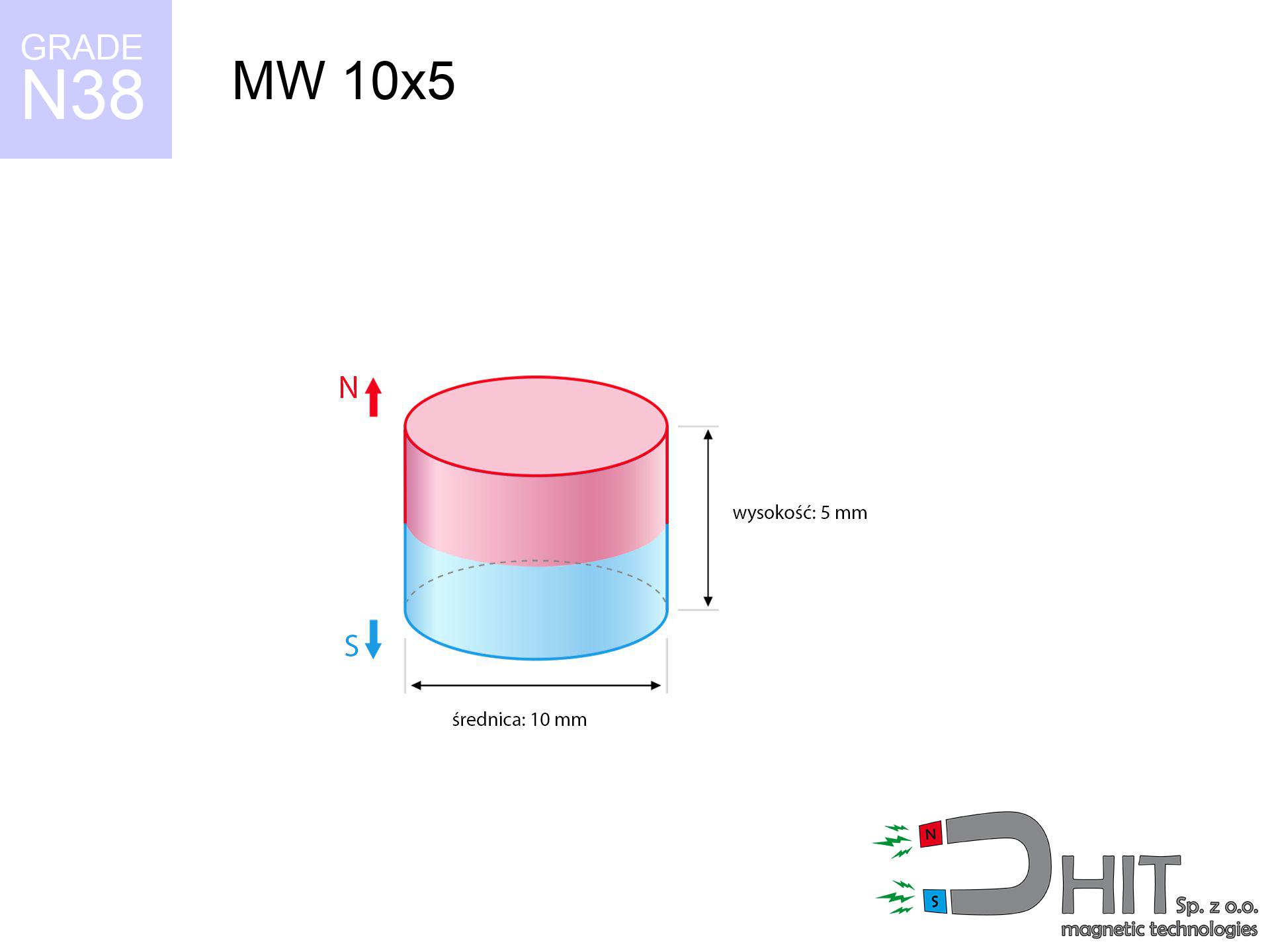
MW 10x5 / N38 - cylindrical magnet
cylindrical magnet
Catalog no 010011
GTIN/EAN: 5906301810100
Diameter Ø
10 mm [±0,1 mm]
Height
5 mm [±0,1 mm]
Weight
2.95 g
Magnetization Direction
↑ axial
Load capacity
3.19 kg / 31.28 N
Magnetic Induction
437.91 mT / 4379 Gs
Coating
[NiCuNi] Nickel
1.513 ZŁ with VAT / pcs + price for transport
1.230 ZŁ net + 23% VAT / pcs
bulk discounts:
Need more?
Call us now
+48 888 99 98 98
otherwise get in touch via
inquiry form
our website.
Parameters as well as appearance of neodymium magnets can be verified on our
online calculation tool.
Orders submitted before 14:00 will be dispatched today!
Product card - MW 10x5 / N38 - cylindrical magnet
Specification / characteristics - MW 10x5 / N38 - cylindrical magnet
| properties | values |
|---|---|
| Cat. no. | 010011 |
| GTIN/EAN | 5906301810100 |
| Production/Distribution | Dhit sp. z o.o. |
| Country of origin | Poland / China / Germany |
| Customs code | 85059029 |
| Diameter Ø | 10 mm [±0,1 mm] |
| Height | 5 mm [±0,1 mm] |
| Weight | 2.95 g |
| Magnetization Direction | ↑ axial |
| Load capacity ~ ? | 3.19 kg / 31.28 N |
| Magnetic Induction ~ ? | 437.91 mT / 4379 Gs |
| Coating | [NiCuNi] Nickel |
| Manufacturing Tolerance | ±0.1 mm |
Magnetic properties of material N38
| properties | values | units |
|---|---|---|
| remenance Br [min. - max.] ? | 12.2-12.6 | kGs |
| remenance Br [min. - max.] ? | 1220-1260 | mT |
| coercivity bHc ? | 10.8-11.5 | kOe |
| coercivity bHc ? | 860-915 | kA/m |
| actual internal force iHc | ≥ 12 | kOe |
| actual internal force iHc | ≥ 955 | kA/m |
| energy density [min. - max.] ? | 36-38 | BH max MGOe |
| energy density [min. - max.] ? | 287-303 | BH max KJ/m |
| max. temperature ? | ≤ 80 | °C |
Physical properties of sintered neodymium magnets Nd2Fe14B at 20°C
| properties | values | units |
|---|---|---|
| Vickers hardness | ≥550 | Hv |
| Density | ≥7.4 | g/cm3 |
| Curie Temperature TC | 312 - 380 | °C |
| Curie Temperature TF | 593 - 716 | °F |
| Specific resistance | 150 | μΩ⋅cm |
| Bending strength | 250 | MPa |
| Compressive strength | 1000~1100 | MPa |
| Thermal expansion parallel (∥) to orientation (M) | (3-4) x 10-6 | °C-1 |
| Thermal expansion perpendicular (⊥) to orientation (M) | -(1-3) x 10-6 | °C-1 |
| Young's modulus | 1.7 x 10⁴ | kg/mm² |
Engineering analysis of the assembly - technical parameters
These values are the result of a physical simulation. Results are based on algorithms for the material Nd2Fe14B. Operational performance may differ from theoretical values. Please consider these calculations as a preliminary roadmap when designing systems.
Table 1: Static force (pull vs gap) - characteristics
MW 10x5 / N38
| Distance (mm) | Induction (Gauss) / mT | Pull Force (kg/lbs/g/N) | Risk Status |
|---|---|---|---|
| 0 mm |
4376 Gs
437.6 mT
|
3.19 kg / 7.03 lbs
3190.0 g / 31.3 N
|
warning |
| 1 mm |
3547 Gs
354.7 mT
|
2.10 kg / 4.62 lbs
2095.9 g / 20.6 N
|
warning |
| 2 mm |
2743 Gs
274.3 mT
|
1.25 kg / 2.76 lbs
1252.9 g / 12.3 N
|
low risk |
| 3 mm |
2068 Gs
206.8 mT
|
0.71 kg / 1.57 lbs
712.2 g / 7.0 N
|
low risk |
| 5 mm |
1161 Gs
116.1 mT
|
0.22 kg / 0.50 lbs
224.7 g / 2.2 N
|
low risk |
| 10 mm |
336 Gs
33.6 mT
|
0.02 kg / 0.04 lbs
18.8 g / 0.2 N
|
low risk |
| 15 mm |
133 Gs
13.3 mT
|
0.00 kg / 0.01 lbs
2.9 g / 0.0 N
|
low risk |
| 20 mm |
65 Gs
6.5 mT
|
0.00 kg / 0.00 lbs
0.7 g / 0.0 N
|
low risk |
| 30 mm |
22 Gs
2.2 mT
|
0.00 kg / 0.00 lbs
0.1 g / 0.0 N
|
low risk |
| 50 mm |
5 Gs
0.5 mT
|
0.00 kg / 0.00 lbs
0.0 g / 0.0 N
|
low risk |
Table 2: Slippage force (vertical surface)
MW 10x5 / N38
| Distance (mm) | Friction coefficient | Pull Force (kg/lbs/g/N) |
|---|---|---|
| 0 mm | Stal (~0.2) |
0.64 kg / 1.41 lbs
638.0 g / 6.3 N
|
| 1 mm | Stal (~0.2) |
0.42 kg / 0.93 lbs
420.0 g / 4.1 N
|
| 2 mm | Stal (~0.2) |
0.25 kg / 0.55 lbs
250.0 g / 2.5 N
|
| 3 mm | Stal (~0.2) |
0.14 kg / 0.31 lbs
142.0 g / 1.4 N
|
| 5 mm | Stal (~0.2) |
0.04 kg / 0.10 lbs
44.0 g / 0.4 N
|
| 10 mm | Stal (~0.2) |
0.00 kg / 0.01 lbs
4.0 g / 0.0 N
|
| 15 mm | Stal (~0.2) |
0.00 kg / 0.00 lbs
0.0 g / 0.0 N
|
| 20 mm | Stal (~0.2) |
0.00 kg / 0.00 lbs
0.0 g / 0.0 N
|
| 30 mm | Stal (~0.2) |
0.00 kg / 0.00 lbs
0.0 g / 0.0 N
|
| 50 mm | Stal (~0.2) |
0.00 kg / 0.00 lbs
0.0 g / 0.0 N
|
Table 3: Wall mounting (shearing) - vertical pull
MW 10x5 / N38
| Surface type | Friction coefficient / % Mocy | Max load (kg/lbs/g/N) |
|---|---|---|
| Raw steel |
µ = 0.3
30% Nominalnej Siły
|
0.96 kg / 2.11 lbs
957.0 g / 9.4 N
|
| Painted steel (standard) |
µ = 0.2
20% Nominalnej Siły
|
0.64 kg / 1.41 lbs
638.0 g / 6.3 N
|
| Oily/slippery steel |
µ = 0.1
10% Nominalnej Siły
|
0.32 kg / 0.70 lbs
319.0 g / 3.1 N
|
| Magnet with anti-slip rubber |
µ = 0.5
50% Nominalnej Siły
|
1.60 kg / 3.52 lbs
1595.0 g / 15.6 N
|
Table 4: Material efficiency (substrate influence) - power losses
MW 10x5 / N38
| Steel thickness (mm) | % power | Real pull force (kg/lbs/g/N) |
|---|---|---|
| 0.5 mm |
|
0.32 kg / 0.70 lbs
319.0 g / 3.1 N
|
| 1 mm |
|
0.80 kg / 1.76 lbs
797.5 g / 7.8 N
|
| 2 mm |
|
1.60 kg / 3.52 lbs
1595.0 g / 15.6 N
|
| 3 mm |
|
2.39 kg / 5.27 lbs
2392.5 g / 23.5 N
|
| 5 mm |
|
3.19 kg / 7.03 lbs
3190.0 g / 31.3 N
|
| 10 mm |
|
3.19 kg / 7.03 lbs
3190.0 g / 31.3 N
|
| 11 mm |
|
3.19 kg / 7.03 lbs
3190.0 g / 31.3 N
|
| 12 mm |
|
3.19 kg / 7.03 lbs
3190.0 g / 31.3 N
|
Table 5: Thermal stability (material behavior) - power drop
MW 10x5 / N38
| Ambient temp. (°C) | Power loss | Remaining pull (kg/lbs/g/N) | Status |
|---|---|---|---|
| 20 °C | 0.0% |
3.19 kg / 7.03 lbs
3190.0 g / 31.3 N
|
OK |
| 40 °C | -2.2% |
3.12 kg / 6.88 lbs
3119.8 g / 30.6 N
|
OK |
| 60 °C | -4.4% |
3.05 kg / 6.72 lbs
3049.6 g / 29.9 N
|
|
| 80 °C | -6.6% |
2.98 kg / 6.57 lbs
2979.5 g / 29.2 N
|
|
| 100 °C | -28.8% |
2.27 kg / 5.01 lbs
2271.3 g / 22.3 N
|
Table 6: Magnet-Magnet interaction (repulsion) - field collision
MW 10x5 / N38
| Gap (mm) | Attraction (kg/lbs) (N-S) | Sliding Force (kg/lbs/g/N) | Repulsion (kg/lbs) (N-N) |
|---|---|---|---|
| 0 mm |
9.27 kg / 20.44 lbs
5 534 Gs
|
1.39 kg / 3.07 lbs
1391 g / 13.6 N
|
N/A |
| 1 mm |
7.63 kg / 16.83 lbs
7 941 Gs
|
1.15 kg / 2.52 lbs
1145 g / 11.2 N
|
6.87 kg / 15.15 lbs
~0 Gs
|
| 2 mm |
6.09 kg / 13.43 lbs
7 094 Gs
|
0.91 kg / 2.01 lbs
914 g / 9.0 N
|
5.48 kg / 12.09 lbs
~0 Gs
|
| 3 mm |
4.75 kg / 10.48 lbs
6 265 Gs
|
0.71 kg / 1.57 lbs
713 g / 7.0 N
|
4.28 kg / 9.43 lbs
~0 Gs
|
| 5 mm |
2.76 kg / 6.08 lbs
4 772 Gs
|
0.41 kg / 0.91 lbs
413 g / 4.1 N
|
2.48 kg / 5.47 lbs
~0 Gs
|
| 10 mm |
0.65 kg / 1.44 lbs
2 323 Gs
|
0.10 kg / 0.22 lbs
98 g / 1.0 N
|
0.59 kg / 1.30 lbs
~0 Gs
|
| 20 mm |
0.05 kg / 0.12 lbs
673 Gs
|
0.01 kg / 0.02 lbs
8 g / 0.1 N
|
0.05 kg / 0.11 lbs
~0 Gs
|
| 50 mm |
0.00 kg / 0.00 lbs
72 Gs
|
0.00 kg / 0.00 lbs
0 g / 0.0 N
|
0.00 kg / 0.00 lbs
~0 Gs
|
| 60 mm |
0.00 kg / 0.00 lbs
44 Gs
|
0.00 kg / 0.00 lbs
0 g / 0.0 N
|
0.00 kg / 0.00 lbs
~0 Gs
|
| 70 mm |
0.00 kg / 0.00 lbs
29 Gs
|
0.00 kg / 0.00 lbs
0 g / 0.0 N
|
0.00 kg / 0.00 lbs
~0 Gs
|
| 80 mm |
0.00 kg / 0.00 lbs
20 Gs
|
0.00 kg / 0.00 lbs
0 g / 0.0 N
|
0.00 kg / 0.00 lbs
~0 Gs
|
| 90 mm |
0.00 kg / 0.00 lbs
14 Gs
|
0.00 kg / 0.00 lbs
0 g / 0.0 N
|
0.00 kg / 0.00 lbs
~0 Gs
|
| 100 mm |
0.00 kg / 0.00 lbs
11 Gs
|
0.00 kg / 0.00 lbs
0 g / 0.0 N
|
0.00 kg / 0.00 lbs
~0 Gs
|
Table 7: Safety (HSE) (electronics) - precautionary measures
MW 10x5 / N38
| Object / Device | Limit (Gauss) / mT | Safe distance |
|---|---|---|
| Pacemaker | 5 Gs (0.5 mT) | 5.5 cm |
| Hearing aid | 10 Gs (1.0 mT) | 4.0 cm |
| Timepiece | 20 Gs (2.0 mT) | 3.5 cm |
| Phone / Smartphone | 40 Gs (4.0 mT) | 2.5 cm |
| Remote | 50 Gs (5.0 mT) | 2.5 cm |
| Payment card | 400 Gs (40.0 mT) | 1.0 cm |
| HDD hard drive | 600 Gs (60.0 mT) | 1.0 cm |
Table 8: Impact energy (cracking risk) - collision effects
MW 10x5 / N38
| Start from (mm) | Speed (km/h) | Energy (J) | Predicted outcome |
|---|---|---|---|
| 10 mm |
33.29 km/h
(9.25 m/s)
|
0.13 J | |
| 30 mm |
57.44 km/h
(15.96 m/s)
|
0.38 J | |
| 50 mm |
74.16 km/h
(20.60 m/s)
|
0.63 J | |
| 100 mm |
104.87 km/h
(29.13 m/s)
|
1.25 J |
Table 9: Coating parameters (durability)
MW 10x5 / N38
| Technical parameter | Value / Description |
|---|---|
| Coating type | [NiCuNi] Nickel |
| Layer structure | Nickel - Copper - Nickel |
| Layer thickness | 10-20 µm |
| Salt spray test (SST) ? | 24 h |
| Recommended environment | Indoors only (dry) |
Table 10: Electrical data (Pc)
MW 10x5 / N38
| Parameter | Value | SI Unit / Description |
|---|---|---|
| Magnetic Flux | 3 489 Mx | 34.9 µWb |
| Pc Coefficient | 0.59 | Low (Flat) |
Table 11: Hydrostatics and buoyancy
MW 10x5 / N38
| Environment | Effective steel pull | Effect |
|---|---|---|
| Air (land) | 3.19 kg | Standard |
| Water (riverbed) |
3.65 kg
(+0.46 kg buoyancy gain)
|
+14.5% |
1. Sliding resistance
*Caution: On a vertical wall, the magnet retains merely ~20% of its perpendicular strength.
2. Steel saturation
*Thin steel (e.g. 0.5mm PC case) severely weakens the holding force.
3. Heat tolerance
*For N38 grade, the max working temp is 80°C.
4. Demagnetization curve and operating point (B-H)
chart generated for the permeance coefficient Pc (Permeance Coefficient) = 0.59
This simulation demonstrates the magnetic stability of the selected magnet under specific geometric conditions. The solid red line represents the demagnetization curve (material potential), while the dashed blue line is the load line based on the magnet's geometry. The Pc (Permeance Coefficient), also known as the load line slope, is a dimensionless value that describes the relationship between the magnet's shape and its magnetic stability. The intersection of these two lines (the black dot) is the operating point — it determines the actual magnetic flux density generated by the magnet in this specific configuration. A higher Pc value means the magnet is more 'slender' (tall relative to its area), resulting in a higher operating point and better resistance to irreversible demagnetization caused by external fields or temperature. A value of 0.42 is relatively low (typical for flat magnets), meaning the operating point is closer to the 'knee' of the curve — caution is advised when operating at temperatures near the maximum limit to avoid strength loss.
Material specification
| iron (Fe) | 64% – 68% |
| neodymium (Nd) | 29% – 32% |
| boron (B) | 1.1% – 1.2% |
| dysprosium (Dy) | 0.5% – 2.0% |
| coating (Ni-Cu-Ni) | < 0.05% |
Environmental data
| recyclability (EoL) | 100% |
| recycled raw materials | ~10% (pre-cons) |
| carbon footprint | low / zredukowany |
| waste code (EWC) | 16 02 16 |
Other offers


![SM 32x300 [2xM8] / N52 - magnetic separator](https://cdn3.dhit.pl/graphics/products/sm-32x300-2xm8-luf.jpg "SM 32x300 [2xM8] / N52 - magnetic separator")

Strengths as well as weaknesses of Nd2Fe14B magnets.
Advantages
- They retain full power for nearly 10 years – the drop is just ~1% (in theory),
- They show high resistance to demagnetization induced by external magnetic fields,
- The use of an shiny layer of noble metals (nickel, gold, silver) causes the element to present itself better,
- Magnetic induction on the working part of the magnet turns out to be strong,
- Thanks to resistance to high temperature, they can operate (depending on the shape) even at temperatures up to 230°C and higher...
- Thanks to modularity in constructing and the capacity to adapt to client solutions,
- Significant place in future technologies – they are used in computer drives, brushless drives, medical devices, and complex engineering applications.
- Compactness – despite small sizes they provide effective action, making them ideal for precision applications
Disadvantages
- They are fragile upon too strong impacts. To avoid cracks, it is worth securing magnets using a steel holder. Such protection not only protects the magnet but also increases its resistance to damage
- Neodymium magnets lose their force under the influence of heating. As soon as 80°C is exceeded, many of them start losing their force. Therefore, we recommend our special magnets marked [AH], which maintain stability even at temperatures up to 230°C
- Magnets exposed to a humid environment can corrode. Therefore when using outdoors, we advise using waterproof magnets made of rubber, plastic or other material resistant to moisture
- Limited possibility of creating nuts in the magnet and complicated shapes - preferred is casing - mounting mechanism.
- Possible danger resulting from small fragments of magnets are risky, when accidentally swallowed, which is particularly important in the context of child safety. It is also worth noting that tiny parts of these devices are able to complicate diagnosis medical after entering the body.
- Due to neodymium price, their price exceeds standard values,
Lifting parameters
Maximum lifting capacity of the magnet – what it depends on?
- using a plate made of low-carbon steel, functioning as a ideal flux conductor
- whose transverse dimension reaches at least 10 mm
- with an polished touching surface
- with direct contact (without impurities)
- under perpendicular application of breakaway force (90-degree angle)
- in temp. approx. 20°C
Practical lifting capacity: influencing factors
- Air gap (between the magnet and the plate), because even a microscopic distance (e.g. 0.5 mm) can cause a decrease in force by up to 50% (this also applies to varnish, rust or dirt).
- Pull-off angle – remember that the magnet has greatest strength perpendicularly. Under shear forces, the capacity drops drastically, often to levels of 20-30% of the maximum value.
- Base massiveness – insufficiently thick steel does not close the flux, causing part of the power to be escaped to the other side.
- Metal type – different alloys reacts the same. Alloy additives weaken the interaction with the magnet.
- Base smoothness – the more even the plate, the larger the contact zone and higher the lifting capacity. Unevenness acts like micro-gaps.
- Heat – NdFeB sinters have a negative temperature coefficient. At higher temperatures they are weaker, and at low temperatures they can be stronger (up to a certain limit).
Holding force was checked on a smooth steel plate of 20 mm thickness, when the force acted perpendicularly, whereas under attempts to slide the magnet the load capacity is reduced by as much as 75%. Additionally, even a minimal clearance between the magnet’s surface and the plate decreases the holding force.
Safety rules for work with NdFeB magnets
Allergic reactions
Allergy Notice: The Ni-Cu-Ni coating contains nickel. If skin irritation occurs, immediately stop working with magnets and wear gloves.
Eye protection
Despite the nickel coating, the material is brittle and cannot withstand shocks. Avoid impacts, as the magnet may crumble into sharp, dangerous pieces.
Hand protection
Watch your fingers. Two powerful magnets will snap together immediately with a force of several hundred kilograms, destroying anything in their path. Be careful!
Heat warning
Watch the temperature. Exposing the magnet to high heat will destroy its magnetic structure and strength.
Fire risk
Powder created during cutting of magnets is combustible. Do not drill into magnets without proper cooling and knowledge.
GPS and phone interference
A powerful magnetic field negatively affects the operation of magnetometers in phones and navigation systems. Do not bring magnets near a device to avoid breaking the sensors.
Conscious usage
Handle with care. Neodymium magnets act from a long distance and snap with massive power, often quicker than you can move away.
Warning for heart patients
Individuals with a pacemaker have to keep an large gap from magnets. The magnetic field can stop the functioning of the life-saving device.
Magnetic media
Device Safety: Strong magnets can damage data carriers and delicate electronics (pacemakers, medical aids, mechanical watches).
Keep away from children
Strictly keep magnets away from children. Risk of swallowing is high, and the consequences of magnets clamping inside the body are life-threatening.
Tabela kosztu i czasu dostawy
Płatność przed wysyłką:

GLS kurier
Przesyłka będzie u Ciebie za 2-3 dni
14.99 ZŁ

InPost Paczkomaty 24/7
Przesyłka będzie u Ciebie za 1-2 dni
12.30 ZŁ
Płatność przy odbiorze (pobranie):
GLS kurier
Przesyłka będzie u Ciebie za 1-2 dni
23.00 ZŁ
Rate the product
Your rating