
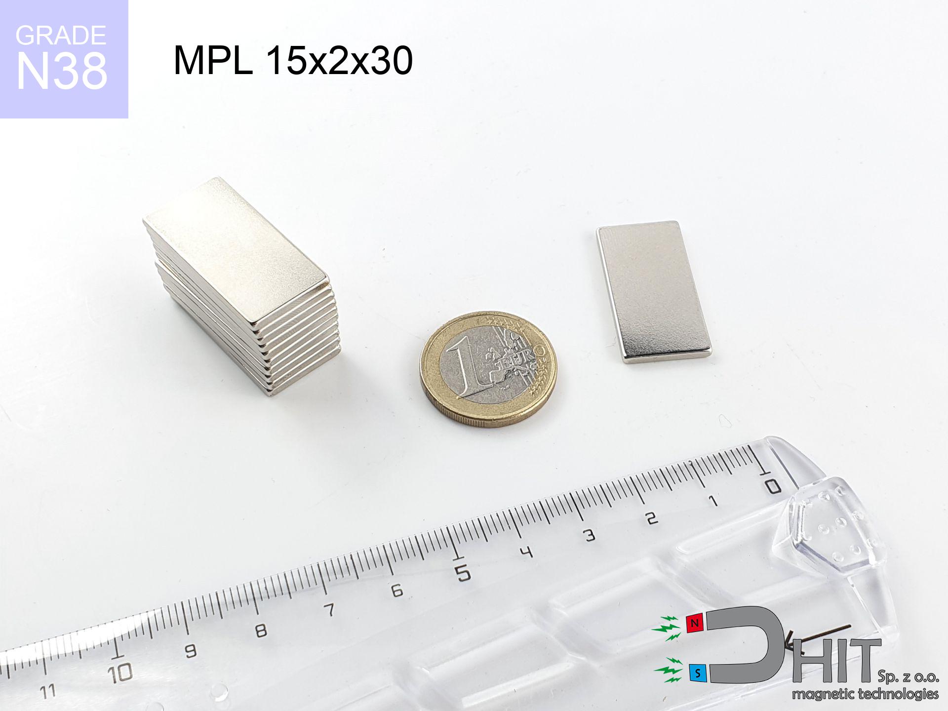
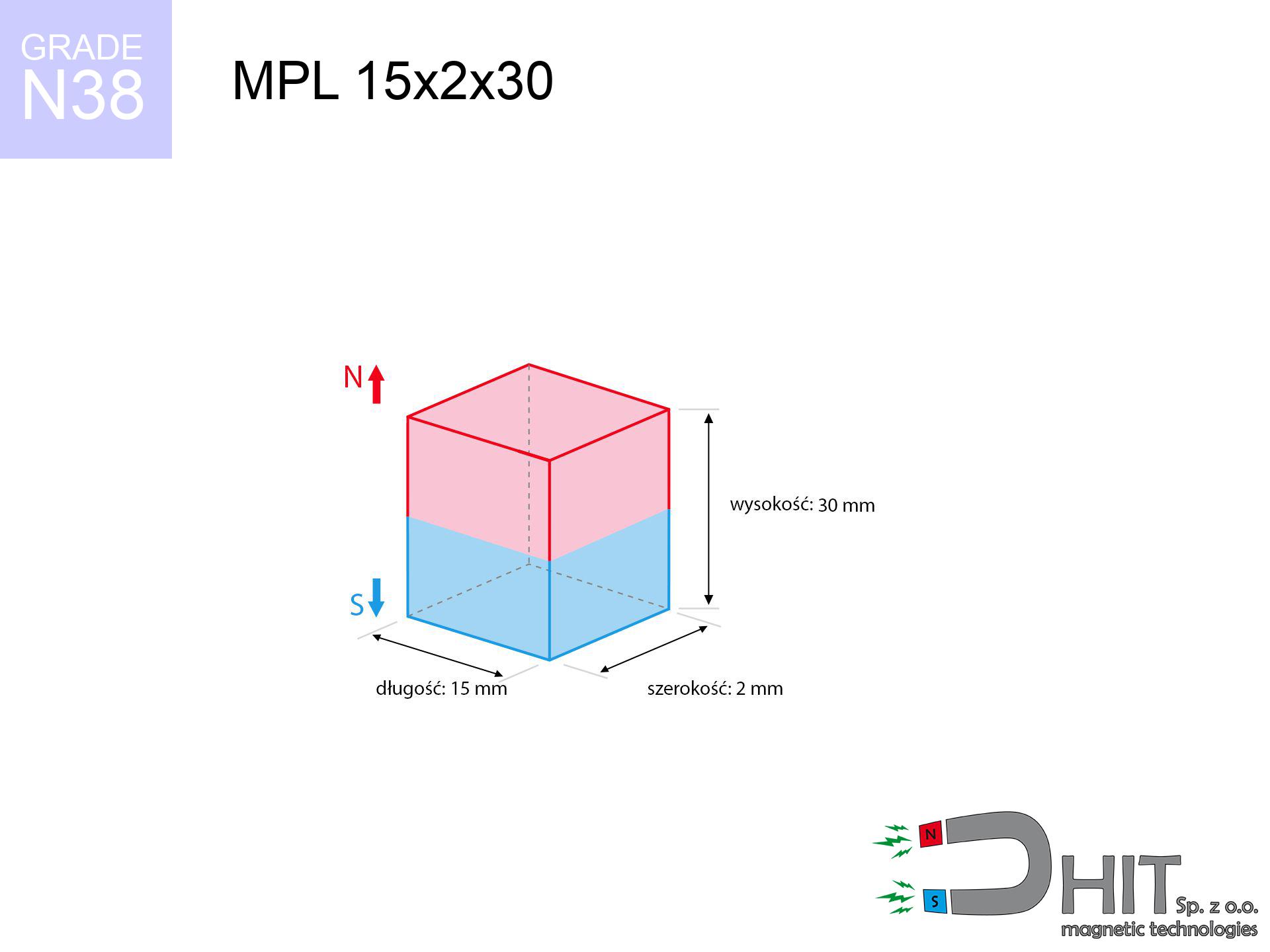
MPL 15x2x30 / N38 - lamellar magnet
lamellar magnet
Catalog no 020121
GTIN/EAN: 5906301811275
length
15 mm [±0,1 mm]
Width
2 mm [±0,1 mm]
Height
30 mm [±0,1 mm]
Weight
6.75 g
Magnetization Direction
→ diametrical
Load capacity
0.68 kg / 6.68 N
Magnetic Induction
614.34 mT / 6143 Gs
Coating
[NiCuNi] Nickel
4.75 ZŁ with VAT / pcs + price for transport
3.86 ZŁ net + 23% VAT / pcs
bulk discounts:
Need more?
Call us now
+48 22 499 98 98
or drop us a message using
our online form
our website.
Strength and appearance of magnets can be estimated using our
magnetic mass calculator.
Same-day processing for orders placed before 14:00.
Detailed specification - MPL 15x2x30 / N38 - lamellar magnet
Specification / characteristics - MPL 15x2x30 / N38 - lamellar magnet
| properties | values |
|---|---|
| Cat. no. | 020121 |
| GTIN/EAN | 5906301811275 |
| Production/Distribution | Dhit sp. z o.o. |
| Country of origin | Poland / China / Germany |
| Customs code | 85059029 |
| length | 15 mm [±0,1 mm] |
| Width | 2 mm [±0,1 mm] |
| Height | 30 mm [±0,1 mm] |
| Weight | 6.75 g |
| Magnetization Direction | → diametrical |
| Load capacity ~ ? | 0.68 kg / 6.68 N |
| Magnetic Induction ~ ? | 614.34 mT / 6143 Gs |
| Coating | [NiCuNi] Nickel |
| Manufacturing Tolerance | ±0.1 mm |
Magnetic properties of material N38
| properties | values | units |
|---|---|---|
| remenance Br [min. - max.] ? | 12.2-12.6 | kGs |
| remenance Br [min. - max.] ? | 1220-1260 | mT |
| coercivity bHc ? | 10.8-11.5 | kOe |
| coercivity bHc ? | 860-915 | kA/m |
| actual internal force iHc | ≥ 12 | kOe |
| actual internal force iHc | ≥ 955 | kA/m |
| energy density [min. - max.] ? | 36-38 | BH max MGOe |
| energy density [min. - max.] ? | 287-303 | BH max KJ/m |
| max. temperature ? | ≤ 80 | °C |
Physical properties of sintered neodymium magnets Nd2Fe14B at 20°C
| properties | values | units |
|---|---|---|
| Vickers hardness | ≥550 | Hv |
| Density | ≥7.4 | g/cm3 |
| Curie Temperature TC | 312 - 380 | °C |
| Curie Temperature TF | 593 - 716 | °F |
| Specific resistance | 150 | μΩ⋅cm |
| Bending strength | 250 | MPa |
| Compressive strength | 1000~1100 | MPa |
| Thermal expansion parallel (∥) to orientation (M) | (3-4) x 10-6 | °C-1 |
| Thermal expansion perpendicular (⊥) to orientation (M) | -(1-3) x 10-6 | °C-1 |
| Young's modulus | 1.7 x 10⁴ | kg/mm² |
Technical simulation of the product - data
The following information are the outcome of a engineering simulation. Results rely on models for the class Nd2Fe14B. Actual performance may deviate from the simulation results. Treat these calculations as a preliminary roadmap for designers.
Table 1: Static force (force vs distance) - power drop
MPL 15x2x30 / N38
| Distance (mm) | Induction (Gauss) / mT | Pull Force (kg/lbs/g/N) | Risk Status |
|---|---|---|---|
| 0 mm |
6128 Gs
612.8 mT
|
0.68 kg / 1.50 LBS
680.0 g / 6.7 N
|
safe |
| 1 mm |
3036 Gs
303.6 mT
|
0.17 kg / 0.37 LBS
166.8 g / 1.6 N
|
safe |
| 2 mm |
1736 Gs
173.6 mT
|
0.05 kg / 0.12 LBS
54.5 g / 0.5 N
|
safe |
| 3 mm |
1150 Gs
115.0 mT
|
0.02 kg / 0.05 LBS
23.9 g / 0.2 N
|
safe |
| 5 mm |
623 Gs
62.3 mT
|
0.01 kg / 0.02 LBS
7.0 g / 0.1 N
|
safe |
| 10 mm |
218 Gs
21.8 mT
|
0.00 kg / 0.00 LBS
0.9 g / 0.0 N
|
safe |
| 15 mm |
103 Gs
10.3 mT
|
0.00 kg / 0.00 LBS
0.2 g / 0.0 N
|
safe |
| 20 mm |
58 Gs
5.8 mT
|
0.00 kg / 0.00 LBS
0.1 g / 0.0 N
|
safe |
| 30 mm |
24 Gs
2.4 mT
|
0.00 kg / 0.00 LBS
0.0 g / 0.0 N
|
safe |
| 50 mm |
7 Gs
0.7 mT
|
0.00 kg / 0.00 LBS
0.0 g / 0.0 N
|
safe |
Table 2: Sliding force (vertical surface)
MPL 15x2x30 / N38
| Distance (mm) | Friction coefficient | Pull Force (kg/lbs/g/N) |
|---|---|---|
| 0 mm | Stal (~0.2) |
0.14 kg / 0.30 LBS
136.0 g / 1.3 N
|
| 1 mm | Stal (~0.2) |
0.03 kg / 0.07 LBS
34.0 g / 0.3 N
|
| 2 mm | Stal (~0.2) |
0.01 kg / 0.02 LBS
10.0 g / 0.1 N
|
| 3 mm | Stal (~0.2) |
0.00 kg / 0.01 LBS
4.0 g / 0.0 N
|
| 5 mm | Stal (~0.2) |
0.00 kg / 0.00 LBS
2.0 g / 0.0 N
|
| 10 mm | Stal (~0.2) |
0.00 kg / 0.00 LBS
0.0 g / 0.0 N
|
| 15 mm | Stal (~0.2) |
0.00 kg / 0.00 LBS
0.0 g / 0.0 N
|
| 20 mm | Stal (~0.2) |
0.00 kg / 0.00 LBS
0.0 g / 0.0 N
|
| 30 mm | Stal (~0.2) |
0.00 kg / 0.00 LBS
0.0 g / 0.0 N
|
| 50 mm | Stal (~0.2) |
0.00 kg / 0.00 LBS
0.0 g / 0.0 N
|
Table 3: Vertical assembly (shearing) - vertical pull
MPL 15x2x30 / N38
| Surface type | Friction coefficient / % Mocy | Max load (kg/lbs/g/N) |
|---|---|---|
| Raw steel |
µ = 0.3
30% Nominalnej Siły
|
0.20 kg / 0.45 LBS
204.0 g / 2.0 N
|
| Painted steel (standard) |
µ = 0.2
20% Nominalnej Siły
|
0.14 kg / 0.30 LBS
136.0 g / 1.3 N
|
| Oily/slippery steel |
µ = 0.1
10% Nominalnej Siły
|
0.07 kg / 0.15 LBS
68.0 g / 0.7 N
|
| Magnet with anti-slip rubber |
µ = 0.5
50% Nominalnej Siły
|
0.34 kg / 0.75 LBS
340.0 g / 3.3 N
|
Table 4: Steel thickness (substrate influence) - power losses
MPL 15x2x30 / N38
| Steel thickness (mm) | % power | Real pull force (kg/lbs/g/N) |
|---|---|---|
| 0.5 mm |
|
0.07 kg / 0.15 LBS
68.0 g / 0.7 N
|
| 1 mm |
|
0.17 kg / 0.37 LBS
170.0 g / 1.7 N
|
| 2 mm |
|
0.34 kg / 0.75 LBS
340.0 g / 3.3 N
|
| 3 mm |
|
0.51 kg / 1.12 LBS
510.0 g / 5.0 N
|
| 5 mm |
|
0.68 kg / 1.50 LBS
680.0 g / 6.7 N
|
| 10 mm |
|
0.68 kg / 1.50 LBS
680.0 g / 6.7 N
|
| 11 mm |
|
0.68 kg / 1.50 LBS
680.0 g / 6.7 N
|
| 12 mm |
|
0.68 kg / 1.50 LBS
680.0 g / 6.7 N
|
Table 5: Thermal stability (stability) - resistance threshold
MPL 15x2x30 / N38
| Ambient temp. (°C) | Power loss | Remaining pull (kg/lbs/g/N) | Status |
|---|---|---|---|
| 20 °C | 0.0% |
0.68 kg / 1.50 LBS
680.0 g / 6.7 N
|
OK |
| 40 °C | -2.2% |
0.67 kg / 1.47 LBS
665.0 g / 6.5 N
|
OK |
| 60 °C | -4.4% |
0.65 kg / 1.43 LBS
650.1 g / 6.4 N
|
OK |
| 80 °C | -6.6% |
0.64 kg / 1.40 LBS
635.1 g / 6.2 N
|
|
| 100 °C | -28.8% |
0.48 kg / 1.07 LBS
484.2 g / 4.7 N
|
Table 6: Two magnets (repulsion) - field collision
MPL 15x2x30 / N38
| Gap (mm) | Attraction (kg/lbs) (N-S) | Shear Strength (kg/lbs/g/N) | Repulsion (kg/lbs) (N-N) |
|---|---|---|---|
| 0 mm |
6.95 kg / 15.31 LBS
6 152 Gs
|
1.04 kg / 2.30 LBS
1042 g / 10.2 N
|
N/A |
| 1 mm |
3.45 kg / 7.62 LBS
8 643 Gs
|
0.52 kg / 1.14 LBS
518 g / 5.1 N
|
3.11 kg / 6.85 LBS
~0 Gs
|
| 2 mm |
1.70 kg / 3.76 LBS
6 071 Gs
|
0.26 kg / 0.56 LBS
256 g / 2.5 N
|
1.53 kg / 3.38 LBS
~0 Gs
|
| 3 mm |
0.93 kg / 2.05 LBS
4 482 Gs
|
0.14 kg / 0.31 LBS
139 g / 1.4 N
|
0.84 kg / 1.84 LBS
~0 Gs
|
| 5 mm |
0.36 kg / 0.79 LBS
2 788 Gs
|
0.05 kg / 0.12 LBS
54 g / 0.5 N
|
0.32 kg / 0.71 LBS
~0 Gs
|
| 10 mm |
0.07 kg / 0.16 LBS
1 247 Gs
|
0.01 kg / 0.02 LBS
11 g / 0.1 N
|
0.06 kg / 0.14 LBS
~0 Gs
|
| 20 mm |
0.01 kg / 0.02 LBS
435 Gs
|
0.00 kg / 0.00 LBS
1 g / 0.0 N
|
0.00 kg / 0.00 LBS
~0 Gs
|
| 50 mm |
0.00 kg / 0.00 LBS
71 Gs
|
0.00 kg / 0.00 LBS
0 g / 0.0 N
|
0.00 kg / 0.00 LBS
~0 Gs
|
| 60 mm |
0.00 kg / 0.00 LBS
47 Gs
|
0.00 kg / 0.00 LBS
0 g / 0.0 N
|
0.00 kg / 0.00 LBS
~0 Gs
|
| 70 mm |
0.00 kg / 0.00 LBS
33 Gs
|
0.00 kg / 0.00 LBS
0 g / 0.0 N
|
0.00 kg / 0.00 LBS
~0 Gs
|
| 80 mm |
0.00 kg / 0.00 LBS
24 Gs
|
0.00 kg / 0.00 LBS
0 g / 0.0 N
|
0.00 kg / 0.00 LBS
~0 Gs
|
| 90 mm |
0.00 kg / 0.00 LBS
18 Gs
|
0.00 kg / 0.00 LBS
0 g / 0.0 N
|
0.00 kg / 0.00 LBS
~0 Gs
|
| 100 mm |
0.00 kg / 0.00 LBS
14 Gs
|
0.00 kg / 0.00 LBS
0 g / 0.0 N
|
0.00 kg / 0.00 LBS
~0 Gs
|
Table 7: Safety (HSE) (electronics) - warnings
MPL 15x2x30 / N38
| Object / Device | Limit (Gauss) / mT | Safe distance |
|---|---|---|
| Pacemaker | 5 Gs (0.5 mT) | 6.0 cm |
| Hearing aid | 10 Gs (1.0 mT) | 4.5 cm |
| Timepiece | 20 Gs (2.0 mT) | 3.5 cm |
| Phone / Smartphone | 40 Gs (4.0 mT) | 2.5 cm |
| Car key | 50 Gs (5.0 mT) | 2.5 cm |
| Payment card | 400 Gs (40.0 mT) | 1.0 cm |
| HDD hard drive | 600 Gs (60.0 mT) | 1.0 cm |
Table 8: Impact energy (kinetic energy) - warning
MPL 15x2x30 / N38
| Start from (mm) | Speed (km/h) | Energy (J) | Predicted outcome |
|---|---|---|---|
| 10 mm |
10.13 km/h
(2.81 m/s)
|
0.03 J | |
| 30 mm |
17.53 km/h
(4.87 m/s)
|
0.08 J | |
| 50 mm |
22.63 km/h
(6.29 m/s)
|
0.13 J | |
| 100 mm |
32.01 km/h
(8.89 m/s)
|
0.27 J |
Table 9: Surface protection spec
MPL 15x2x30 / N38
| Technical parameter | Value / Description |
|---|---|
| Coating type | [NiCuNi] Nickel |
| Layer structure | Nickel - Copper - Nickel |
| Layer thickness | 10-20 µm |
| Salt spray test (SST) ? | 24 h |
| Recommended environment | Indoors only (dry) |
Table 10: Construction data (Flux)
MPL 15x2x30 / N38
| Parameter | Value | SI Unit / Description |
|---|---|---|
| Magnetic Flux | 2 210 Mx | 22.1 µWb |
| Pc Coefficient | 1.54 | High (Stable) |
Table 11: Hydrostatics and buoyancy
MPL 15x2x30 / N38
| Environment | Effective steel pull | Effect |
|---|---|---|
| Air (land) | 0.68 kg | Standard |
| Water (riverbed) |
0.78 kg
(+0.10 kg buoyancy gain)
|
+14.5% |
1. Shear force
*Caution: On a vertical surface, the magnet retains merely approx. 20-30% of its max power.
2. Steel saturation
*Thin steel (e.g. computer case) drastically weakens the holding force.
3. Thermal stability
*For standard magnets, the critical limit is 80°C.
4. Demagnetization curve and operating point (B-H)
chart generated for the permeance coefficient Pc (Permeance Coefficient) = 1.54
The chart above illustrates the magnetic characteristics of the material within the second quadrant of the hysteresis loop. The solid red line represents the demagnetization curve (material potential), while the dashed blue line is the load line based on the magnet's geometry. The Pc (Permeance Coefficient), also known as the load line slope, is a dimensionless value that describes the relationship between the magnet's shape and its magnetic stability. The intersection of these two lines (the black dot) is the operating point — it determines the actual magnetic flux density generated by the magnet in this specific configuration. A higher Pc value means the magnet is more 'slender' (tall relative to its area), resulting in a higher operating point and better resistance to irreversible demagnetization caused by external fields or temperature. A value of 0.42 is relatively low (typical for flat magnets), meaning the operating point is closer to the 'knee' of the curve — caution is advised when operating at temperatures near the maximum limit to avoid strength loss.
Material specification
| iron (Fe) | 64% – 68% |
| neodymium (Nd) | 29% – 32% |
| boron (B) | 1.1% – 1.2% |
| dysprosium (Dy) | 0.5% – 2.0% |
| coating (Ni-Cu-Ni) | < 0.05% |
Sustainability
| recyclability (EoL) | 100% |
| recycled raw materials | ~10% (pre-cons) |
| carbon footprint | low / zredukowany |
| waste code (EWC) | 16 02 16 |
See also offers

![BM 650x180x70 [4x M8] - magnetic beam](https://cdn3.dhit.pl/graphics/products/bm-650x180x70-4x-m8-laj.jpg "BM 650x180x70 [4x M8] - magnetic beam")


Advantages as well as disadvantages of neodymium magnets.
Strengths
- They virtually do not lose strength, because even after 10 years the performance loss is only ~1% (according to literature),
- They are resistant to demagnetization induced by external magnetic fields,
- The use of an shiny coating of noble metals (nickel, gold, silver) causes the element to be more visually attractive,
- The surface of neodymium magnets generates a intense magnetic field – this is a distinguishing feature,
- Made from properly selected components, these magnets show impressive resistance to high heat, enabling them to function (depending on their form) at temperatures up to 230°C and above...
- Possibility of custom modeling and adapting to concrete requirements,
- Fundamental importance in high-tech industry – they are used in computer drives, electric drive systems, diagnostic systems, and complex engineering applications.
- Compactness – despite small sizes they offer powerful magnetic field, making them ideal for precision applications
Cons
- Susceptibility to cracking is one of their disadvantages. Upon strong impact they can break. We recommend keeping them in a special holder, which not only secures them against impacts but also increases their durability
- Neodymium magnets lose their power under the influence of heating. As soon as 80°C is exceeded, many of them start losing their power. Therefore, we recommend our special magnets marked [AH], which maintain durability even at temperatures up to 230°C
- They oxidize in a humid environment. For use outdoors we suggest using waterproof magnets e.g. in rubber, plastic
- We suggest a housing - magnetic mount, due to difficulties in realizing nuts inside the magnet and complex forms.
- Health risk related to microscopic parts of magnets can be dangerous, in case of ingestion, which gains importance in the context of child safety. Additionally, tiny parts of these magnets are able to disrupt the diagnostic process medical when they are in the body.
- Higher cost of purchase is a significant factor to consider compared to ceramic magnets, especially in budget applications
Pull force analysis
Highest magnetic holding force – what it depends on?
- with the use of a sheet made of low-carbon steel, ensuring maximum field concentration
- whose transverse dimension is min. 10 mm
- characterized by even structure
- without the slightest air gap between the magnet and steel
- for force acting at a right angle (in the magnet axis)
- in temp. approx. 20°C
Lifting capacity in practice – influencing factors
- Gap between magnet and steel – every millimeter of distance (caused e.g. by veneer or unevenness) diminishes the pulling force, often by half at just 0.5 mm.
- Direction of force – maximum parameter is reached only during pulling at a 90° angle. The resistance to sliding of the magnet along the surface is usually many times lower (approx. 1/5 of the lifting capacity).
- Substrate thickness – to utilize 100% power, the steel must be sufficiently thick. Paper-thin metal limits the lifting capacity (the magnet "punches through" it).
- Steel grade – the best choice is pure iron steel. Cast iron may generate lower lifting capacity.
- Surface condition – ground elements ensure maximum contact, which increases force. Uneven metal weaken the grip.
- Temperature – heating the magnet results in weakening of induction. Check the thermal limit for a given model.
Lifting capacity testing was conducted on a smooth plate of optimal thickness, under perpendicular forces, whereas under shearing force the load capacity is reduced by as much as 5 times. In addition, even a minimal clearance between the magnet’s surface and the plate reduces the lifting capacity.
H&S for magnets
Power loss in heat
Do not overheat. NdFeB magnets are sensitive to temperature. If you need resistance above 80°C, inquire about HT versions (H, SH, UH).
Beware of splinters
Beware of splinters. Magnets can fracture upon uncontrolled impact, ejecting sharp fragments into the air. Wear goggles.
Swallowing risk
Always keep magnets away from children. Choking hazard is high, and the effects of magnets connecting inside the body are life-threatening.
Threat to navigation
GPS units and smartphones are extremely susceptible to magnetic fields. Close proximity with a powerful NdFeB magnet can permanently damage the sensors in your phone.
Dust is flammable
Combustion risk: Neodymium dust is highly flammable. Avoid machining magnets without safety gear as this risks ignition.
Data carriers
Device Safety: Strong magnets can ruin data carriers and delicate electronics (pacemakers, medical aids, mechanical watches).
Health Danger
Health Alert: Neodymium magnets can turn off pacemakers and defibrillators. Do not approach if you have electronic implants.
Caution required
Handle with care. Rare earth magnets attract from a long distance and connect with massive power, often quicker than you can react.
Avoid contact if allergic
It is widely known that nickel (standard magnet coating) is a strong allergen. If your skin reacts to metals, refrain from direct skin contact or choose coated magnets.
Crushing force
Pinching hazard: The attraction force is so immense that it can cause hematomas, pinching, and broken bones. Protective gloves are recommended.
Tabela kosztu i czasu dostawy
Płatność przed wysyłką:

GLS kurier
Przesyłka będzie u Ciebie za 2-3 dni
14.99 ZŁ

InPost Paczkomaty 24/7
Przesyłka będzie u Ciebie za 1-2 dni
12.30 ZŁ
Płatność przy odbiorze (pobranie):
GLS kurier
Przesyłka będzie u Ciebie za 1-2 dni
23.00 ZŁ
Rate the product
Your rating