
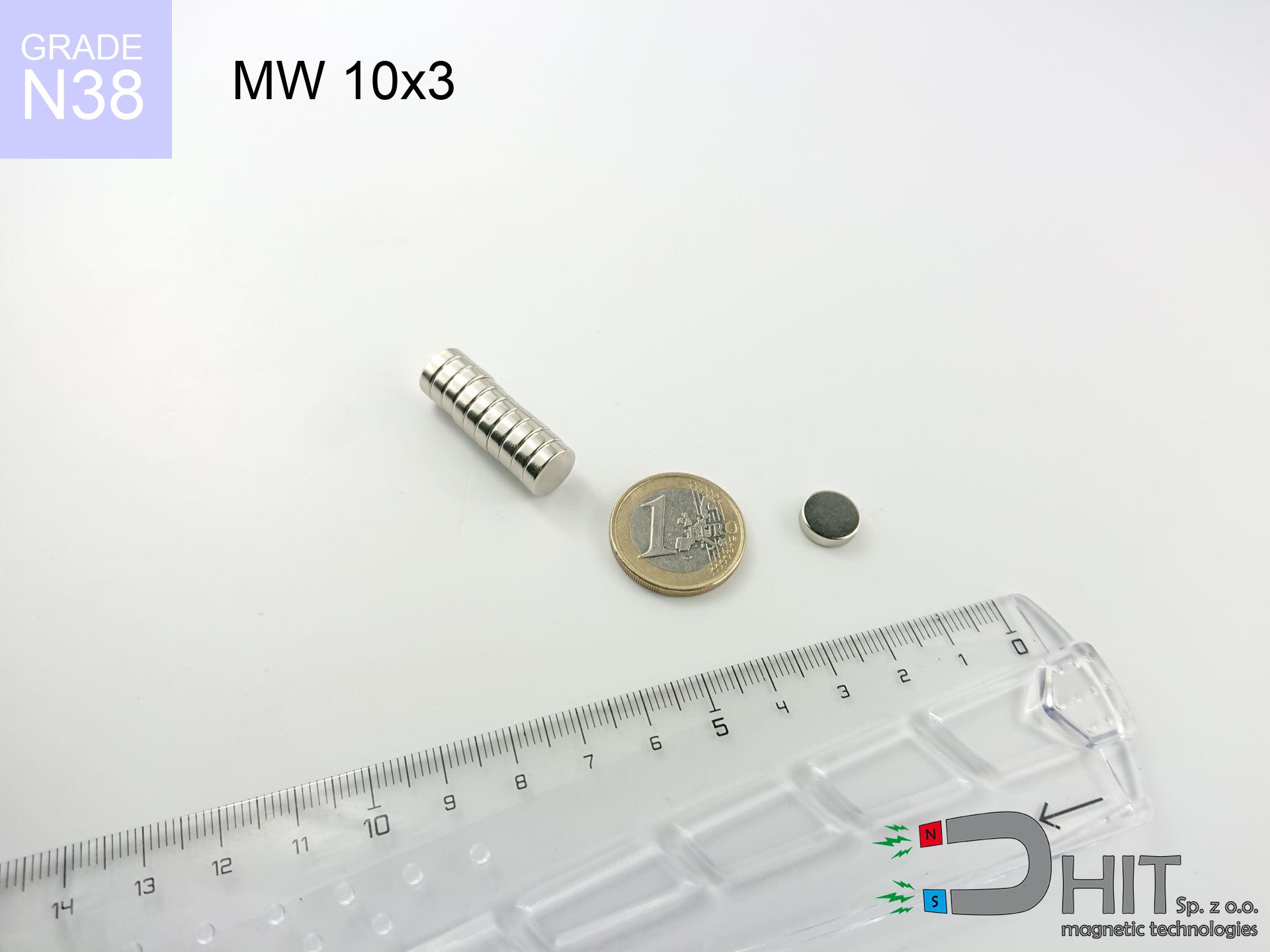
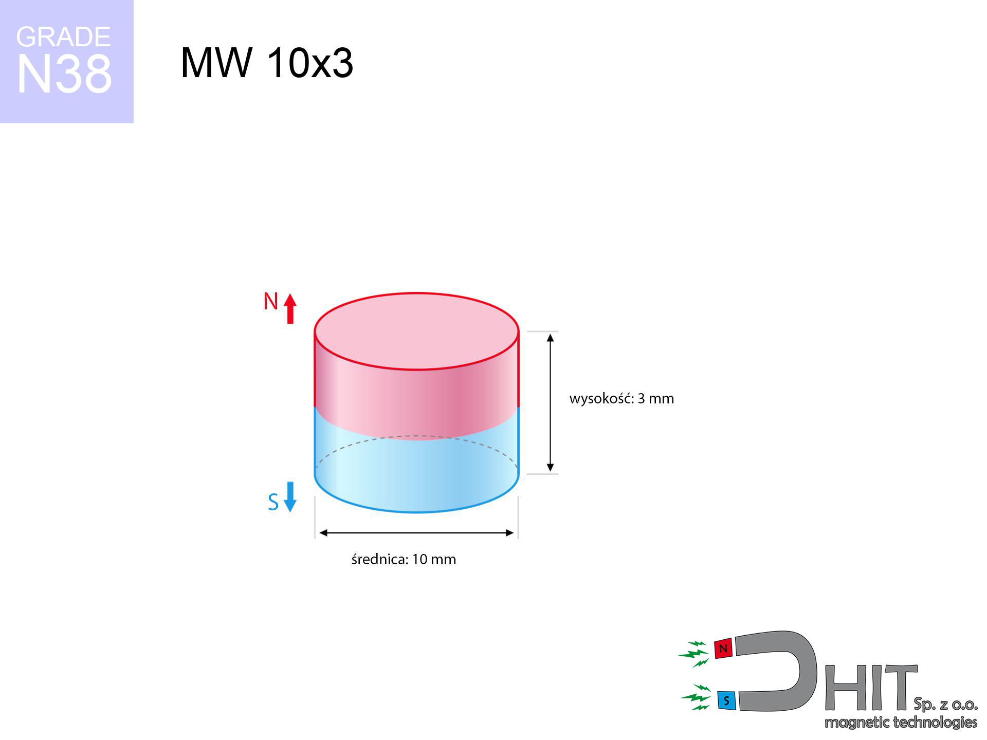
MW 10x3 / N38 - cylindrical magnet
cylindrical magnet
Catalog no 010008
GTIN/EAN: 5906301810070
Diameter Ø
10 mm [±0,1 mm]
Height
3 mm [±0,1 mm]
Weight
1.77 g
Magnetization Direction
↑ axial
Load capacity
2.15 kg / 21.04 N
Magnetic Induction
318.70 mT / 3187 Gs
Coating
[NiCuNi] Nickel
0.726 ZŁ with VAT / pcs + price for transport
0.590 ZŁ net + 23% VAT / pcs
bulk discounts:
Need more?
Call us
+48 888 99 98 98
alternatively send us a note using
inquiry form
our website.
Weight as well as structure of a magnet can be verified with our
our magnetic calculator.
Same-day processing for orders placed before 14:00.
Technical of the product - MW 10x3 / N38 - cylindrical magnet
Specification / characteristics - MW 10x3 / N38 - cylindrical magnet
| properties | values |
|---|---|
| Cat. no. | 010008 |
| GTIN/EAN | 5906301810070 |
| Production/Distribution | Dhit sp. z o.o. |
| Country of origin | Poland / China / Germany |
| Customs code | 85059029 |
| Diameter Ø | 10 mm [±0,1 mm] |
| Height | 3 mm [±0,1 mm] |
| Weight | 1.77 g |
| Magnetization Direction | ↑ axial |
| Load capacity ~ ? | 2.15 kg / 21.04 N |
| Magnetic Induction ~ ? | 318.70 mT / 3187 Gs |
| Coating | [NiCuNi] Nickel |
| Manufacturing Tolerance | ±0.1 mm |
Magnetic properties of material N38
| properties | values | units |
|---|---|---|
| remenance Br [min. - max.] ? | 12.2-12.6 | kGs |
| remenance Br [min. - max.] ? | 1220-1260 | mT |
| coercivity bHc ? | 10.8-11.5 | kOe |
| coercivity bHc ? | 860-915 | kA/m |
| actual internal force iHc | ≥ 12 | kOe |
| actual internal force iHc | ≥ 955 | kA/m |
| energy density [min. - max.] ? | 36-38 | BH max MGOe |
| energy density [min. - max.] ? | 287-303 | BH max KJ/m |
| max. temperature ? | ≤ 80 | °C |
Physical properties of sintered neodymium magnets Nd2Fe14B at 20°C
| properties | values | units |
|---|---|---|
| Vickers hardness | ≥550 | Hv |
| Density | ≥7.4 | g/cm3 |
| Curie Temperature TC | 312 - 380 | °C |
| Curie Temperature TF | 593 - 716 | °F |
| Specific resistance | 150 | μΩ⋅cm |
| Bending strength | 250 | MPa |
| Compressive strength | 1000~1100 | MPa |
| Thermal expansion parallel (∥) to orientation (M) | (3-4) x 10-6 | °C-1 |
| Thermal expansion perpendicular (⊥) to orientation (M) | -(1-3) x 10-6 | °C-1 |
| Young's modulus | 1.7 x 10⁴ | kg/mm² |
Technical modeling of the magnet - technical parameters
Presented values represent the result of a physical simulation. Values rely on algorithms for the class Nd2Fe14B. Real-world parameters may differ from theoretical values. Please consider these data as a reference point during assembly planning.
Table 1: Static force (force vs gap) - interaction chart
MW 10x3 / N38
| Distance (mm) | Induction (Gauss) / mT | Pull Force (kg/lbs/g/N) | Risk Status |
|---|---|---|---|
| 0 mm |
3185 Gs
318.5 mT
|
2.15 kg / 4.74 lbs
2150.0 g / 21.1 N
|
medium risk |
| 1 mm |
2657 Gs
265.7 mT
|
1.50 kg / 3.30 lbs
1496.2 g / 14.7 N
|
low risk |
| 2 mm |
2081 Gs
208.1 mT
|
0.92 kg / 2.02 lbs
918.1 g / 9.0 N
|
low risk |
| 3 mm |
1573 Gs
157.3 mT
|
0.52 kg / 1.16 lbs
524.4 g / 5.1 N
|
low risk |
| 5 mm |
874 Gs
87.4 mT
|
0.16 kg / 0.36 lbs
161.7 g / 1.6 N
|
low risk |
| 10 mm |
241 Gs
24.1 mT
|
0.01 kg / 0.03 lbs
12.3 g / 0.1 N
|
low risk |
| 15 mm |
92 Gs
9.2 mT
|
0.00 kg / 0.00 lbs
1.8 g / 0.0 N
|
low risk |
| 20 mm |
44 Gs
4.4 mT
|
0.00 kg / 0.00 lbs
0.4 g / 0.0 N
|
low risk |
| 30 mm |
14 Gs
1.4 mT
|
0.00 kg / 0.00 lbs
0.0 g / 0.0 N
|
low risk |
| 50 mm |
3 Gs
0.3 mT
|
0.00 kg / 0.00 lbs
0.0 g / 0.0 N
|
low risk |
Table 2: Slippage hold (vertical surface)
MW 10x3 / N38
| Distance (mm) | Friction coefficient | Pull Force (kg/lbs/g/N) |
|---|---|---|
| 0 mm | Stal (~0.2) |
0.43 kg / 0.95 lbs
430.0 g / 4.2 N
|
| 1 mm | Stal (~0.2) |
0.30 kg / 0.66 lbs
300.0 g / 2.9 N
|
| 2 mm | Stal (~0.2) |
0.18 kg / 0.41 lbs
184.0 g / 1.8 N
|
| 3 mm | Stal (~0.2) |
0.10 kg / 0.23 lbs
104.0 g / 1.0 N
|
| 5 mm | Stal (~0.2) |
0.03 kg / 0.07 lbs
32.0 g / 0.3 N
|
| 10 mm | Stal (~0.2) |
0.00 kg / 0.00 lbs
2.0 g / 0.0 N
|
| 15 mm | Stal (~0.2) |
0.00 kg / 0.00 lbs
0.0 g / 0.0 N
|
| 20 mm | Stal (~0.2) |
0.00 kg / 0.00 lbs
0.0 g / 0.0 N
|
| 30 mm | Stal (~0.2) |
0.00 kg / 0.00 lbs
0.0 g / 0.0 N
|
| 50 mm | Stal (~0.2) |
0.00 kg / 0.00 lbs
0.0 g / 0.0 N
|
Table 3: Wall mounting (shearing) - behavior on slippery surfaces
MW 10x3 / N38
| Surface type | Friction coefficient / % Mocy | Max load (kg/lbs/g/N) |
|---|---|---|
| Raw steel |
µ = 0.3
30% Nominalnej Siły
|
0.64 kg / 1.42 lbs
645.0 g / 6.3 N
|
| Painted steel (standard) |
µ = 0.2
20% Nominalnej Siły
|
0.43 kg / 0.95 lbs
430.0 g / 4.2 N
|
| Oily/slippery steel |
µ = 0.1
10% Nominalnej Siły
|
0.22 kg / 0.47 lbs
215.0 g / 2.1 N
|
| Magnet with anti-slip rubber |
µ = 0.5
50% Nominalnej Siły
|
1.08 kg / 2.37 lbs
1075.0 g / 10.5 N
|
Table 4: Material efficiency (saturation) - power losses
MW 10x3 / N38
| Steel thickness (mm) | % power | Real pull force (kg/lbs/g/N) |
|---|---|---|
| 0.5 mm |
|
0.22 kg / 0.47 lbs
215.0 g / 2.1 N
|
| 1 mm |
|
0.54 kg / 1.18 lbs
537.5 g / 5.3 N
|
| 2 mm |
|
1.08 kg / 2.37 lbs
1075.0 g / 10.5 N
|
| 3 mm |
|
1.61 kg / 3.55 lbs
1612.5 g / 15.8 N
|
| 5 mm |
|
2.15 kg / 4.74 lbs
2150.0 g / 21.1 N
|
| 10 mm |
|
2.15 kg / 4.74 lbs
2150.0 g / 21.1 N
|
| 11 mm |
|
2.15 kg / 4.74 lbs
2150.0 g / 21.1 N
|
| 12 mm |
|
2.15 kg / 4.74 lbs
2150.0 g / 21.1 N
|
Table 5: Thermal resistance (stability) - thermal limit
MW 10x3 / N38
| Ambient temp. (°C) | Power loss | Remaining pull (kg/lbs/g/N) | Status |
|---|---|---|---|
| 20 °C | 0.0% |
2.15 kg / 4.74 lbs
2150.0 g / 21.1 N
|
OK |
| 40 °C | -2.2% |
2.10 kg / 4.64 lbs
2102.7 g / 20.6 N
|
OK |
| 60 °C | -4.4% |
2.06 kg / 4.53 lbs
2055.4 g / 20.2 N
|
|
| 80 °C | -6.6% |
2.01 kg / 4.43 lbs
2008.1 g / 19.7 N
|
|
| 100 °C | -28.8% |
1.53 kg / 3.37 lbs
1530.8 g / 15.0 N
|
Table 6: Two magnets (repulsion) - forces in the system
MW 10x3 / N38
| Gap (mm) | Attraction (kg/lbs) (N-S) | Lateral Force (kg/lbs/g/N) | Repulsion (kg/lbs) (N-N) |
|---|---|---|---|
| 0 mm |
4.91 kg / 10.83 lbs
4 754 Gs
|
0.74 kg / 1.62 lbs
737 g / 7.2 N
|
N/A |
| 1 mm |
4.18 kg / 9.22 lbs
5 877 Gs
|
0.63 kg / 1.38 lbs
627 g / 6.2 N
|
3.76 kg / 8.30 lbs
~0 Gs
|
| 2 mm |
3.42 kg / 7.54 lbs
5 314 Gs
|
0.51 kg / 1.13 lbs
513 g / 5.0 N
|
3.08 kg / 6.78 lbs
~0 Gs
|
| 3 mm |
2.71 kg / 5.98 lbs
4 732 Gs
|
0.41 kg / 0.90 lbs
407 g / 4.0 N
|
2.44 kg / 5.38 lbs
~0 Gs
|
| 5 mm |
1.59 kg / 3.52 lbs
3 630 Gs
|
0.24 kg / 0.53 lbs
239 g / 2.3 N
|
1.44 kg / 3.16 lbs
~0 Gs
|
| 10 mm |
0.37 kg / 0.81 lbs
1 747 Gs
|
0.06 kg / 0.12 lbs
55 g / 0.5 N
|
0.33 kg / 0.73 lbs
~0 Gs
|
| 20 mm |
0.03 kg / 0.06 lbs
483 Gs
|
0.00 kg / 0.01 lbs
4 g / 0.0 N
|
0.03 kg / 0.06 lbs
~0 Gs
|
| 50 mm |
0.00 kg / 0.00 lbs
48 Gs
|
0.00 kg / 0.00 lbs
0 g / 0.0 N
|
0.00 kg / 0.00 lbs
~0 Gs
|
| 60 mm |
0.00 kg / 0.00 lbs
29 Gs
|
0.00 kg / 0.00 lbs
0 g / 0.0 N
|
0.00 kg / 0.00 lbs
~0 Gs
|
| 70 mm |
0.00 kg / 0.00 lbs
19 Gs
|
0.00 kg / 0.00 lbs
0 g / 0.0 N
|
0.00 kg / 0.00 lbs
~0 Gs
|
| 80 mm |
0.00 kg / 0.00 lbs
13 Gs
|
0.00 kg / 0.00 lbs
0 g / 0.0 N
|
0.00 kg / 0.00 lbs
~0 Gs
|
| 90 mm |
0.00 kg / 0.00 lbs
9 Gs
|
0.00 kg / 0.00 lbs
0 g / 0.0 N
|
0.00 kg / 0.00 lbs
~0 Gs
|
| 100 mm |
0.00 kg / 0.00 lbs
7 Gs
|
0.00 kg / 0.00 lbs
0 g / 0.0 N
|
0.00 kg / 0.00 lbs
~0 Gs
|
Table 7: Protective zones (implants) - precautionary measures
MW 10x3 / N38
| Object / Device | Limit (Gauss) / mT | Safe distance |
|---|---|---|
| Pacemaker | 5 Gs (0.5 mT) | 4.5 cm |
| Hearing aid | 10 Gs (1.0 mT) | 3.5 cm |
| Timepiece | 20 Gs (2.0 mT) | 3.0 cm |
| Phone / Smartphone | 40 Gs (4.0 mT) | 2.5 cm |
| Remote | 50 Gs (5.0 mT) | 2.0 cm |
| Payment card | 400 Gs (40.0 mT) | 1.0 cm |
| HDD hard drive | 600 Gs (60.0 mT) | 1.0 cm |
Table 8: Collisions (cracking risk) - collision effects
MW 10x3 / N38
| Start from (mm) | Speed (km/h) | Energy (J) | Predicted outcome |
|---|---|---|---|
| 10 mm |
35.27 km/h
(9.80 m/s)
|
0.08 J | |
| 30 mm |
60.88 km/h
(16.91 m/s)
|
0.25 J | |
| 50 mm |
78.60 km/h
(21.83 m/s)
|
0.42 J | |
| 100 mm |
111.15 km/h
(30.88 m/s)
|
0.84 J |
Table 9: Anti-corrosion coating durability
MW 10x3 / N38
| Technical parameter | Value / Description |
|---|---|
| Coating type | [NiCuNi] Nickel |
| Layer structure | Nickel - Copper - Nickel |
| Layer thickness | 10-20 µm |
| Salt spray test (SST) ? | 24 h |
| Recommended environment | Indoors only (dry) |
Table 10: Construction data (Flux)
MW 10x3 / N38
| Parameter | Value | SI Unit / Description |
|---|---|---|
| Magnetic Flux | 2 694 Mx | 26.9 µWb |
| Pc Coefficient | 0.40 | Low (Flat) |
Table 11: Physics of underwater searching
MW 10x3 / N38
| Environment | Effective steel pull | Effect |
|---|---|---|
| Air (land) | 2.15 kg | Standard |
| Water (riverbed) |
2.46 kg
(+0.31 kg buoyancy gain)
|
+14.5% |
1. Vertical hold
*Note: On a vertical wall, the magnet retains only approx. 20-30% of its perpendicular strength.
2. Plate thickness effect
*Thin steel (e.g. 0.5mm PC case) significantly limits the holding force.
3. Temperature resistance
*For N38 material, the max working temp is 80°C.
4. Demagnetization curve and operating point (B-H)
chart generated for the permeance coefficient Pc (Permeance Coefficient) = 0.40
This simulation demonstrates the magnetic stability of the selected magnet under specific geometric conditions. The solid red line represents the demagnetization curve (material potential), while the dashed blue line is the load line based on the magnet's geometry. The Pc (Permeance Coefficient), also known as the load line slope, is a dimensionless value that describes the relationship between the magnet's shape and its magnetic stability. The intersection of these two lines (the black dot) is the operating point — it determines the actual magnetic flux density generated by the magnet in this specific configuration. A higher Pc value means the magnet is more 'slender' (tall relative to its area), resulting in a higher operating point and better resistance to irreversible demagnetization caused by external fields or temperature. A value of 0.42 is relatively low (typical for flat magnets), meaning the operating point is closer to the 'knee' of the curve — caution is advised when operating at temperatures near the maximum limit to avoid strength loss.
Material specification
| iron (Fe) | 64% – 68% |
| neodymium (Nd) | 29% – 32% |
| boron (B) | 1.1% – 1.2% |
| dysprosium (Dy) | 0.5% – 2.0% |
| coating (Ni-Cu-Ni) | < 0.05% |
Environmental data
| recyclability (EoL) | 100% |
| recycled raw materials | ~10% (pre-cons) |
| carbon footprint | low / zredukowany |
| waste code (EWC) | 16 02 16 |
Other deals
![SM 32x375 [2xM8] / N42 - magnetic separator](https://cdn3.dhit.pl/graphics/products/sm-32x375-2xm8-nif.jpg "SM 32x375 [2xM8] / N42 - magnetic separator")

![SM 32x400 [2xM8] / N42 - magnetic separator](https://cdn3.dhit.pl/graphics/products/sm-32x400-2xm8-tep.jpg "SM 32x400 [2xM8] / N42 - magnetic separator")

Pros and cons of neodymium magnets.
Advantages
- They retain full power for almost ten years – the drop is just ~1% (based on simulations),
- They are resistant to demagnetization induced by external field influence,
- The use of an elegant coating of noble metals (nickel, gold, silver) causes the element to present itself better,
- They feature high magnetic induction at the operating surface, making them more effective,
- Neodymium magnets are characterized by very high magnetic induction on the magnet surface and can function (depending on the form) even at a temperature of 230°C or more...
- Thanks to modularity in constructing and the ability to customize to unusual requirements,
- Wide application in high-tech industry – they are utilized in computer drives, electromotive mechanisms, medical equipment, and multitasking production systems.
- Compactness – despite small sizes they generate large force, making them ideal for precision applications
Weaknesses
- To avoid cracks upon strong impacts, we recommend using special steel holders. Such a solution secures the magnet and simultaneously improves its durability.
- We warn that neodymium magnets can reduce their power at high temperatures. To prevent this, we suggest our specialized [AH] magnets, which work effectively even at 230°C.
- Magnets exposed to a humid environment can rust. Therefore when using outdoors, we recommend using water-impermeable magnets made of rubber, plastic or other material resistant to moisture
- Limited ability of making nuts in the magnet and complicated forms - recommended is casing - magnet mounting.
- Possible danger to health – tiny shards of magnets pose a threat, in case of ingestion, which becomes key in the aspect of protecting the youngest. It is also worth noting that tiny parts of these products can be problematic in diagnostics medical in case of swallowing.
- Higher cost of purchase is one of the disadvantages compared to ceramic magnets, especially in budget applications
Pull force analysis
Maximum lifting force for a neodymium magnet – what affects it?
- using a sheet made of high-permeability steel, serving as a magnetic yoke
- whose thickness equals approx. 10 mm
- with a plane free of scratches
- with direct contact (without paint)
- during pulling in a direction perpendicular to the mounting surface
- in neutral thermal conditions
Magnet lifting force in use – key factors
- Air gap (betwixt the magnet and the metal), because even a microscopic distance (e.g. 0.5 mm) leads to a reduction in lifting capacity by up to 50% (this also applies to varnish, rust or dirt).
- Load vector – maximum parameter is obtained only during perpendicular pulling. The resistance to sliding of the magnet along the surface is usually many times smaller (approx. 1/5 of the lifting capacity).
- Substrate thickness – to utilize 100% power, the steel must be adequately massive. Paper-thin metal limits the lifting capacity (the magnet "punches through" it).
- Plate material – mild steel attracts best. Alloy admixtures reduce magnetic properties and holding force.
- Surface condition – ground elements guarantee perfect abutment, which improves force. Uneven metal weaken the grip.
- Operating temperature – NdFeB sinters have a negative temperature coefficient. At higher temperatures they lose power, and in frost they can be stronger (up to a certain limit).
Lifting capacity was assessed by applying a polished steel plate of suitable thickness (min. 20 mm), under vertically applied force, whereas under parallel forces the holding force is lower. Moreover, even a slight gap between the magnet’s surface and the plate reduces the lifting capacity.
Safe handling of neodymium magnets
Crushing force
Large magnets can crush fingers in a fraction of a second. Do not place your hand between two strong magnets.
Danger to the youngest
Absolutely store magnets away from children. Risk of swallowing is high, and the effects of magnets clamping inside the body are fatal.
Caution required
Use magnets consciously. Their powerful strength can surprise even experienced users. Stay alert and do not underestimate their force.
Precision electronics
A strong magnetic field negatively affects the functioning of magnetometers in phones and GPS navigation. Maintain magnets close to a smartphone to avoid breaking the sensors.
Warning for heart patients
Patients with a heart stimulator have to keep an absolute distance from magnets. The magnetic field can disrupt the functioning of the life-saving device.
Beware of splinters
Neodymium magnets are sintered ceramics, meaning they are fragile like glass. Clashing of two magnets will cause them cracking into small pieces.
Power loss in heat
Standard neodymium magnets (grade N) lose magnetization when the temperature surpasses 80°C. The loss of strength is permanent.
Cards and drives
Powerful magnetic fields can corrupt files on payment cards, hard drives, and other magnetic media. Maintain a gap of at least 10 cm.
Machining danger
Dust produced during cutting of magnets is combustible. Avoid drilling into magnets unless you are an expert.
Nickel coating and allergies
A percentage of the population suffer from a sensitization to Ni, which is the standard coating for NdFeB magnets. Extended handling may cause a rash. We recommend use safety gloves.
Tabela kosztu i czasu dostawy
Płatność przed wysyłką:

GLS kurier
Przesyłka będzie u Ciebie za 2-3 dni
14.99 ZŁ

InPost Paczkomaty 24/7
Przesyłka będzie u Ciebie za 1-2 dni
12.30 ZŁ
Płatność przy odbiorze (pobranie):
GLS kurier
Przesyłka będzie u Ciebie za 1-2 dni
23.00 ZŁ
Rate the product
Your rating