
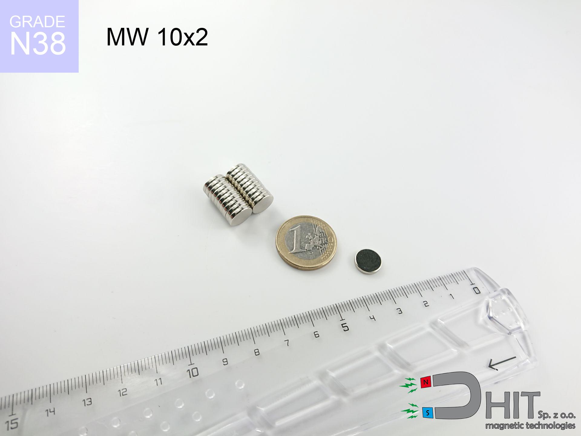
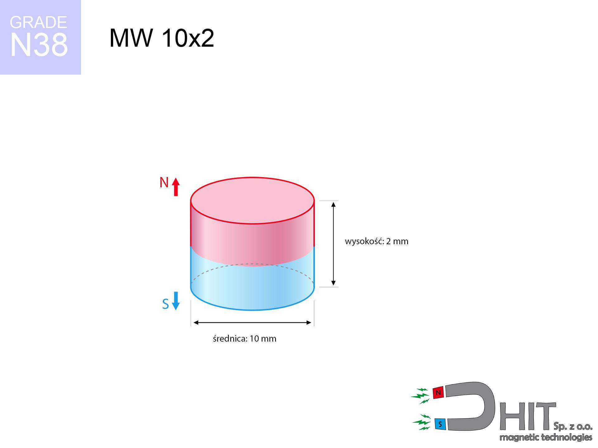
MW 10x2 / N38 - cylindrical magnet
cylindrical magnet
Catalog no 010006
GTIN/EAN: 5906301810056
Diameter Ø
10 mm [±0,1 mm]
Height
2 mm [±0,1 mm]
Weight
1.18 g
Magnetization Direction
↑ axial
Load capacity
1.27 kg / 12.50 N
Magnetic Induction
230.11 mT / 2301 Gs
Coating
[NiCuNi] Nickel
0.467 ZŁ with VAT / pcs + price for transport
0.380 ZŁ net + 23% VAT / pcs
bulk discounts:
Need more?Engineering report for this magnet
Full PDF analysis: pull and shear force, effect of distance, temperature and plate thickness, safety distances and the demagnetization curve.
Call us now
+48 888 99 98 98
alternatively let us know through
request form
our website.
Strength as well as shape of a neodymium magnet can be reviewed on our
our magnetic calculator.
Orders placed before 14:00 will be shipped the same business day.
Detailed specification - MW 10x2 / N38 - cylindrical magnet
Specification / characteristics - MW 10x2 / N38 - cylindrical magnet
| properties | values |
|---|---|
| Cat. no. | 010006 |
| GTIN/EAN | 5906301810056 |
| Production/Distribution | Dhit sp. z o.o. |
| Country of origin | Poland / China / Germany |
| Customs code | 85059029 |
| Diameter Ø | 10 mm [±0,1 mm] |
| Height | 2 mm [±0,1 mm] |
| Weight | 1.18 g |
| Magnetization Direction | ↑ axial |
| Load capacity ~ ? | 1.27 kg / 12.50 N |
| Magnetic Induction ~ ? | 230.11 mT / 2301 Gs |
| Coating | [NiCuNi] Nickel |
| Manufacturing Tolerance | ±0.1 mm |
Magnetic properties of material N38
| properties | values | units |
|---|---|---|
| remenance Br [min. - max.] ? | 12.2-12.6 | kGs |
| remenance Br [min. - max.] ? | 1220-1260 | mT |
| coercivity bHc ? | 10.8-11.5 | kOe |
| coercivity bHc ? | 860-915 | kA/m |
| actual internal force iHc | ≥ 12 | kOe |
| actual internal force iHc | ≥ 955 | kA/m |
| energy density [min. - max.] ? | 36-38 | BH max MGOe |
| energy density [min. - max.] ? | 287-303 | BH max KJ/m |
| max. temperature ? | ≤ 80 | °C |
Physical properties of sintered neodymium magnets Nd2Fe14B at 20°C
| properties | values | units |
|---|---|---|
| Vickers hardness | ≥550 | Hv |
| Density | ≥7.4 | g/cm3 |
| Curie Temperature TC | 312 - 380 | °C |
| Curie Temperature TF | 593 - 716 | °F |
| Specific resistance | 150 | μΩ⋅cm |
| Bending strength | 250 | MPa |
| Compressive strength | 1000~1100 | MPa |
| Thermal expansion parallel (∥) to orientation (M) | (3-4) x 10-6 | °C-1 |
| Thermal expansion perpendicular (⊥) to orientation (M) | -(1-3) x 10-6 | °C-1 |
| Young's modulus | 1.7 x 10⁴ | kg/mm² |
Engineering simulation of the magnet - technical parameters
Presented values constitute the outcome of a physical simulation. Values are based on models for the material Nd2Fe14B. Actual parameters may deviate from the simulation results. Please consider these data as a supplementary guide for designers.
Table 1: Static force (pull vs gap) - characteristics
MW 10x2 / N38
| Distance (mm) | Induction (Gauss) / mT | Pull Force (kg/lbs/g/N) | Risk Status |
|---|---|---|---|
| 0 mm |
2300 Gs
230.0 mT
|
1.27 kg / 2.80 LBS
1270.0 g / 12.5 N
|
weak grip |
| 1 mm |
1974 Gs
197.4 mT
|
0.94 kg / 2.06 LBS
935.3 g / 9.2 N
|
weak grip |
| 2 mm |
1570 Gs
157.0 mT
|
0.59 kg / 1.31 LBS
592.1 g / 5.8 N
|
weak grip |
| 3 mm |
1194 Gs
119.4 mT
|
0.34 kg / 0.75 LBS
342.3 g / 3.4 N
|
weak grip |
| 5 mm |
661 Gs
66.1 mT
|
0.10 kg / 0.23 LBS
104.9 g / 1.0 N
|
weak grip |
| 10 mm |
178 Gs
17.8 mT
|
0.01 kg / 0.02 LBS
7.6 g / 0.1 N
|
weak grip |
| 15 mm |
66 Gs
6.6 mT
|
0.00 kg / 0.00 LBS
1.1 g / 0.0 N
|
weak grip |
| 20 mm |
31 Gs
3.1 mT
|
0.00 kg / 0.00 LBS
0.2 g / 0.0 N
|
weak grip |
| 30 mm |
10 Gs
1.0 mT
|
0.00 kg / 0.00 LBS
0.0 g / 0.0 N
|
weak grip |
| 50 mm |
2 Gs
0.2 mT
|
0.00 kg / 0.00 LBS
0.0 g / 0.0 N
|
weak grip |
Table 2: Vertical hold (wall)
MW 10x2 / N38
| Distance (mm) | Friction coefficient | Pull Force (kg/lbs/g/N) |
|---|---|---|
| 0 mm | Stal (~0.2) |
0.25 kg / 0.56 LBS
254.0 g / 2.5 N
|
| 1 mm | Stal (~0.2) |
0.19 kg / 0.41 LBS
188.0 g / 1.8 N
|
| 2 mm | Stal (~0.2) |
0.12 kg / 0.26 LBS
118.0 g / 1.2 N
|
| 3 mm | Stal (~0.2) |
0.07 kg / 0.15 LBS
68.0 g / 0.7 N
|
| 5 mm | Stal (~0.2) |
0.02 kg / 0.04 LBS
20.0 g / 0.2 N
|
| 10 mm | Stal (~0.2) |
0.00 kg / 0.00 LBS
2.0 g / 0.0 N
|
| 15 mm | Stal (~0.2) |
0.00 kg / 0.00 LBS
0.0 g / 0.0 N
|
| 20 mm | Stal (~0.2) |
0.00 kg / 0.00 LBS
0.0 g / 0.0 N
|
| 30 mm | Stal (~0.2) |
0.00 kg / 0.00 LBS
0.0 g / 0.0 N
|
| 50 mm | Stal (~0.2) |
0.00 kg / 0.00 LBS
0.0 g / 0.0 N
|
Table 3: Vertical assembly (sliding) - behavior on slippery surfaces
MW 10x2 / N38
| Surface type | Friction coefficient / % Mocy | Max load (kg/lbs/g/N) |
|---|---|---|
| Raw steel |
µ = 0.3
30% Nominalnej Siły
|
0.38 kg / 0.84 LBS
381.0 g / 3.7 N
|
| Painted steel (standard) |
µ = 0.2
20% Nominalnej Siły
|
0.25 kg / 0.56 LBS
254.0 g / 2.5 N
|
| Oily/slippery steel |
µ = 0.1
10% Nominalnej Siły
|
0.13 kg / 0.28 LBS
127.0 g / 1.2 N
|
| Magnet with anti-slip rubber |
µ = 0.5
50% Nominalnej Siły
|
0.64 kg / 1.40 LBS
635.0 g / 6.2 N
|
Table 4: Steel thickness (substrate influence) - power losses
MW 10x2 / N38
| Steel thickness (mm) | % power | Real pull force (kg/lbs/g/N) |
|---|---|---|
| 0.5 mm |
|
0.13 kg / 0.28 LBS
127.0 g / 1.2 N
|
| 1 mm |
|
0.32 kg / 0.70 LBS
317.5 g / 3.1 N
|
| 2 mm |
|
0.64 kg / 1.40 LBS
635.0 g / 6.2 N
|
| 3 mm |
|
0.95 kg / 2.10 LBS
952.5 g / 9.3 N
|
| 5 mm |
|
1.27 kg / 2.80 LBS
1270.0 g / 12.5 N
|
| 10 mm |
|
1.27 kg / 2.80 LBS
1270.0 g / 12.5 N
|
| 11 mm |
|
1.27 kg / 2.80 LBS
1270.0 g / 12.5 N
|
| 12 mm |
|
1.27 kg / 2.80 LBS
1270.0 g / 12.5 N
|
Table 5: Thermal stability (stability) - resistance threshold
MW 10x2 / N38
| Ambient temp. (°C) | Power loss | Remaining pull (kg/lbs/g/N) | Status |
|---|---|---|---|
| 20 °C | 0.0% |
1.27 kg / 2.80 LBS
1270.0 g / 12.5 N
|
OK |
| 40 °C | -2.2% |
1.24 kg / 2.74 LBS
1242.1 g / 12.2 N
|
OK |
| 60 °C | -4.4% |
1.21 kg / 2.68 LBS
1214.1 g / 11.9 N
|
|
| 80 °C | -6.6% |
1.19 kg / 2.62 LBS
1186.2 g / 11.6 N
|
|
| 100 °C | -28.8% |
0.90 kg / 1.99 LBS
904.2 g / 8.9 N
|
Table 6: Two magnets (repulsion) - field range
MW 10x2 / N38
| Gap (mm) | Attraction (kg/lbs) (N-S) | Lateral Force (kg/lbs/g/N) | Repulsion (kg/lbs) (N-N) |
|---|---|---|---|
| 0 mm |
2.56 kg / 5.65 LBS
3 867 Gs
|
0.38 kg / 0.85 LBS
384 g / 3.8 N
|
N/A |
| 1 mm |
2.25 kg / 4.96 LBS
4 312 Gs
|
0.34 kg / 0.74 LBS
338 g / 3.3 N
|
2.03 kg / 4.46 LBS
~0 Gs
|
| 2 mm |
1.89 kg / 4.16 LBS
3 948 Gs
|
0.28 kg / 0.62 LBS
283 g / 2.8 N
|
1.70 kg / 3.74 LBS
~0 Gs
|
| 3 mm |
1.52 kg / 3.36 LBS
3 548 Gs
|
0.23 kg / 0.50 LBS
229 g / 2.2 N
|
1.37 kg / 3.02 LBS
~0 Gs
|
| 5 mm |
0.92 kg / 2.02 LBS
2 750 Gs
|
0.14 kg / 0.30 LBS
137 g / 1.3 N
|
0.82 kg / 1.82 LBS
~0 Gs
|
| 10 mm |
0.21 kg / 0.47 LBS
1 322 Gs
|
0.03 kg / 0.07 LBS
32 g / 0.3 N
|
0.19 kg / 0.42 LBS
~0 Gs
|
| 20 mm |
0.02 kg / 0.03 LBS
355 Gs
|
0.00 kg / 0.01 LBS
2 g / 0.0 N
|
0.01 kg / 0.03 LBS
~0 Gs
|
| 50 mm |
0.00 kg / 0.00 LBS
33 Gs
|
0.00 kg / 0.00 LBS
0 g / 0.0 N
|
0.00 kg / 0.00 LBS
~0 Gs
|
| 60 mm |
0.00 kg / 0.00 LBS
20 Gs
|
0.00 kg / 0.00 LBS
0 g / 0.0 N
|
0.00 kg / 0.00 LBS
~0 Gs
|
| 70 mm |
0.00 kg / 0.00 LBS
13 Gs
|
0.00 kg / 0.00 LBS
0 g / 0.0 N
|
0.00 kg / 0.00 LBS
~0 Gs
|
| 80 mm |
0.00 kg / 0.00 LBS
9 Gs
|
0.00 kg / 0.00 LBS
0 g / 0.0 N
|
0.00 kg / 0.00 LBS
~0 Gs
|
| 90 mm |
0.00 kg / 0.00 LBS
6 Gs
|
0.00 kg / 0.00 LBS
0 g / 0.0 N
|
0.00 kg / 0.00 LBS
~0 Gs
|
| 100 mm |
0.00 kg / 0.00 LBS
5 Gs
|
0.00 kg / 0.00 LBS
0 g / 0.0 N
|
0.00 kg / 0.00 LBS
~0 Gs
|
Table 7: Hazards (electronics) - precautionary measures
MW 10x2 / N38
| Object / Device | Limit (Gauss) / mT | Safe distance |
|---|---|---|
| Pacemaker | 5 Gs (0.5 mT) | 4.0 cm |
| Hearing aid | 10 Gs (1.0 mT) | 3.5 cm |
| Mechanical watch | 20 Gs (2.0 mT) | 2.5 cm |
| Phone / Smartphone | 40 Gs (4.0 mT) | 2.0 cm |
| Car key | 50 Gs (5.0 mT) | 2.0 cm |
| Payment card | 400 Gs (40.0 mT) | 1.0 cm |
| HDD hard drive | 600 Gs (60.0 mT) | 1.0 cm |
Table 8: Impact energy (cracking risk) - warning
MW 10x2 / N38
| Start from (mm) | Speed (km/h) | Energy (J) | Predicted outcome |
|---|---|---|---|
| 10 mm |
33.21 km/h
(9.22 m/s)
|
0.05 J | |
| 30 mm |
57.31 km/h
(15.92 m/s)
|
0.15 J | |
| 50 mm |
73.98 km/h
(20.55 m/s)
|
0.25 J | |
| 100 mm |
104.63 km/h
(29.06 m/s)
|
0.50 J |
Table 9: Anti-corrosion coating durability
MW 10x2 / N38
| Technical parameter | Value / Description |
|---|---|
| Coating type | [NiCuNi] Nickel |
| Layer structure | Nickel - Copper - Nickel |
| Layer thickness | 10-20 µm |
| Salt spray test (SST) ? | 24 h |
| Recommended environment | Indoors only (dry) |
Table 10: Electrical data (Flux)
MW 10x2 / N38
| Parameter | Value | SI Unit / Description |
|---|---|---|
| Magnetic Flux | 2 097 Mx | 21.0 µWb |
| Pc Coefficient | 0.29 | Low (Flat) |
Table 11: Underwater work (magnet fishing)
MW 10x2 / N38
| Environment | Effective steel pull | Effect |
|---|---|---|
| Air (land) | 1.27 kg | Standard |
| Water (riverbed) |
1.45 kg
(+0.18 kg buoyancy gain)
|
+14.5% |
1. Shear force
*Caution: On a vertical surface, the magnet holds just approx. 20-30% of its perpendicular strength.
2. Efficiency vs thickness
*Thin steel (e.g. 0.5mm PC case) significantly reduces the holding force.
3. Power loss vs temp
*For standard magnets, the max working temp is 80°C.
4. Demagnetization curve and operating point (B-H)
chart generated for the permeance coefficient Pc (Permeance Coefficient) = 0.29
This simulation demonstrates the magnetic stability of the selected magnet under specific geometric conditions. The solid red line represents the demagnetization curve (material potential), while the dashed blue line is the load line based on the magnet's geometry. The Pc (Permeance Coefficient), also known as the load line slope, is a dimensionless value that describes the relationship between the magnet's shape and its magnetic stability. The intersection of these two lines (the black dot) is the operating point — it determines the actual magnetic flux density generated by the magnet in this specific configuration. A higher Pc value means the magnet is more 'slender' (tall relative to its area), resulting in a higher operating point and better resistance to irreversible demagnetization caused by external fields or temperature. A value of 0.42 is relatively low (typical for flat magnets), meaning the operating point is closer to the 'knee' of the curve — caution is advised when operating at temperatures near the maximum limit to avoid strength loss.
Material specification
| iron (Fe) | 64% – 68% |
| neodymium (Nd) | 29% – 32% |
| boron (B) | 1.1% – 1.2% |
| dysprosium (Dy) | 0.5% – 2.0% |
| coating (Ni-Cu-Ni) | < 0.05% |
Sustainability
| recyclability (EoL) | 100% |
| recycled raw materials | ~10% (pre-cons) |
| carbon footprint | low / zredukowany |
| waste code (EWC) | 16 02 16 |
Other offers


![UMP 75x25 [M10x3] GW F200 PLATINIUM Lina / N52 - search holder](https://cdn3.dhit.pl/graphics/products/ump-75x25-m10x3-gw-f200-platinium-lina-wiz.jpg "UMP 75x25 [M10x3] GW F200 PLATINIUM Lina / N52 - search holder")
Strengths as well as weaknesses of Nd2Fe14B magnets.
Benefits
- Their magnetic field remains stable, and after approximately ten years it drops only by ~1% (theoretically),
- Neodymium magnets are highly resistant to magnetic field loss caused by external magnetic fields,
- Thanks to the smooth finish, the coating of nickel, gold-plated, or silver gives an professional appearance,
- They show high magnetic induction at the operating surface, making them more effective,
- Made from properly selected components, these magnets show impressive resistance to high heat, enabling them to function (depending on their form) at temperatures up to 230°C and above...
- Possibility of detailed creating and modifying to complex requirements,
- Key role in advanced technology sectors – they are utilized in hard drives, motor assemblies, precision medical tools, as well as other advanced devices.
- Relatively small size with high pulling force – neodymium magnets offer strong magnetic field in compact dimensions, which makes them useful in compact constructions
Cons
- At very strong impacts they can crack, therefore we advise placing them in strong housings. A metal housing provides additional protection against damage, as well as increases the magnet's durability.
- NdFeB magnets lose power when exposed to high temperatures. After reaching 80°C, many of them experience permanent drop of power (a factor is the shape and dimensions of the magnet). We offer magnets specially adapted to work at temperatures up to 230°C marked [AH], which are very resistant to heat
- When exposed to humidity, magnets usually rust. To use them in conditions outside, it is recommended to use protective magnets, such as those in rubber or plastics, which prevent oxidation as well as corrosion.
- We recommend cover - magnetic mechanism, due to difficulties in producing nuts inside the magnet and complex forms.
- Potential hazard related to microscopic parts of magnets can be dangerous, if swallowed, which becomes key in the aspect of protecting the youngest. Furthermore, small elements of these products are able to complicate diagnosis medical when they are in the body.
- With large orders the cost of neodymium magnets is economically unviable,
Holding force characteristics
Maximum magnetic pulling force – what contributes to it?
- using a base made of low-carbon steel, serving as a magnetic yoke
- with a thickness minimum 10 mm
- with a plane free of scratches
- with zero gap (without paint)
- under axial force vector (90-degree angle)
- at ambient temperature approx. 20 degrees Celsius
Magnet lifting force in use – key factors
- Clearance – the presence of any layer (paint, dirt, air) interrupts the magnetic circuit, which reduces capacity rapidly (even by 50% at 0.5 mm).
- Force direction – note that the magnet has greatest strength perpendicularly. Under sliding down, the capacity drops significantly, often to levels of 20-30% of the nominal value.
- Substrate thickness – to utilize 100% power, the steel must be sufficiently thick. Thin sheet limits the attraction force (the magnet "punches through" it).
- Metal type – different alloys reacts the same. Alloy additives worsen the attraction effect.
- Surface structure – the smoother and more polished the surface, the larger the contact zone and stronger the hold. Roughness acts like micro-gaps.
- Thermal conditions – NdFeB sinters have a negative temperature coefficient. At higher temperatures they are weaker, and in frost they can be stronger (up to a certain limit).
Lifting capacity was determined with the use of a steel plate with a smooth surface of suitable thickness (min. 20 mm), under vertically applied force, however under attempts to slide the magnet the holding force is lower. In addition, even a minimal clearance between the magnet’s surface and the plate lowers the load capacity.
Safe handling of neodymium magnets
Crushing force
Watch your fingers. Two powerful magnets will snap together immediately with a force of massive weight, crushing everything in their path. Exercise extreme caution!
GPS Danger
Note: neodymium magnets generate a field that interferes with precision electronics. Keep a separation from your mobile, device, and navigation systems.
Allergic reactions
Certain individuals experience a sensitization to Ni, which is the typical protective layer for NdFeB magnets. Extended handling might lead to a rash. We recommend use protective gloves.
Do not underestimate power
Use magnets consciously. Their immense force can shock even experienced users. Plan your moves and do not underestimate their force.
ICD Warning
Health Alert: Neodymium magnets can turn off pacemakers and defibrillators. Stay away if you have medical devices.
Choking Hazard
Product intended for adults. Small elements pose a choking risk, leading to serious injuries. Store out of reach of kids and pets.
Safe distance
Avoid bringing magnets close to a wallet, laptop, or screen. The magnetic field can irreversibly ruin these devices and erase data from cards.
Fire risk
Powder created during grinding of magnets is self-igniting. Do not drill into magnets without proper cooling and knowledge.
Fragile material
NdFeB magnets are ceramic materials, meaning they are prone to chipping. Impact of two magnets leads to them breaking into small pieces.
Permanent damage
Standard neodymium magnets (grade N) lose power when the temperature goes above 80°C. Damage is permanent.
Tabela kosztu i czasu dostawy
Płatność przed wysyłką:

GLS kurier
Przesyłka będzie u Ciebie za 2-3 dni
14.99 ZŁ

InPost Paczkomaty 24/7
Przesyłka będzie u Ciebie za 1-2 dni
12.30 ZŁ
Płatność przy odbiorze (pobranie):
GLS kurier
Przesyłka będzie u Ciebie za 1-2 dni
23.00 ZŁ
Rate the product
Your rating