
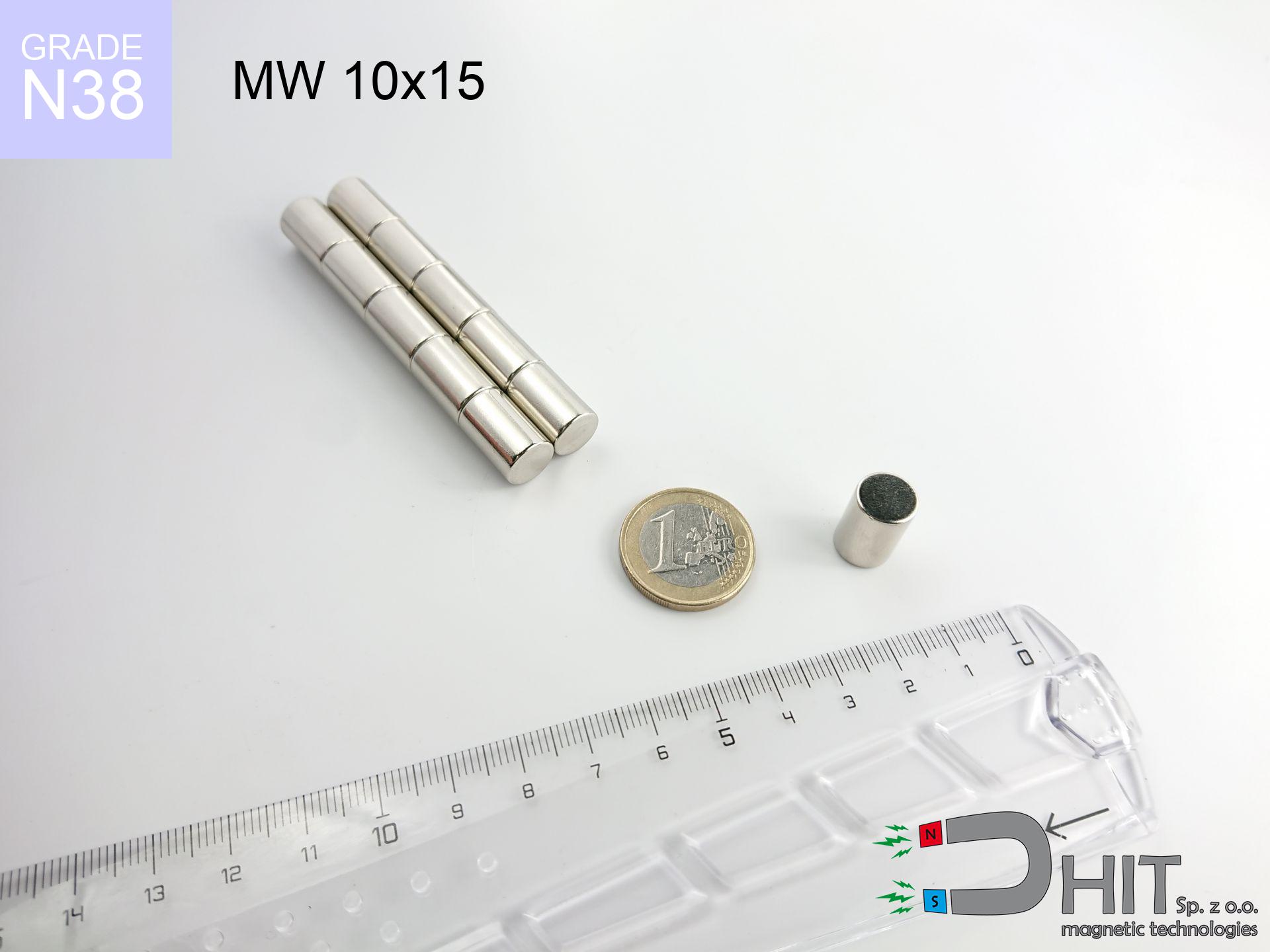
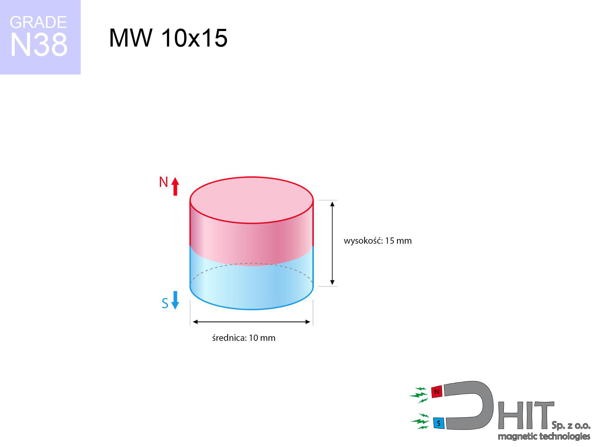
MW 10x15 / N38 - cylindrical magnet
cylindrical magnet
Catalog no 010005
GTIN/EAN: 5906301810049
- Diameter Ø
- 10 mm [±0,1 mm]
- Height
- 15 mm [±0,1 mm]
- Weight
- 8.84 g
- Magnetization Direction
- ↑ axial
- Coating
- [NiCuNi] Nickel
6.15 zł with VAT / pcs + price for transport
5.00 zł net + 23% VAT / pcs
bulk discounts:
Need more?Engineering report for this magnet
Full PDF analysis: pull and shear force, effect of distance, temperature and plate thickness, safety distances and the demagnetization curve.
Contact us by phone
+48 888 99 98 98
otherwise drop us a message through
inquiry form
our website.
Weight along with structure of neodymium magnets can be tested using our
magnetic mass calculator.
Same-day processing for orders placed before 14:00.
Physical properties - MW 10x15 / N38 - cylindrical magnet
Specification / characteristics - MW 10x15 / N38 - cylindrical magnet
| properties | values |
|---|---|
| Cat. no. | 010005 |
| GTIN/EAN | 5906301810049 |
| Production/Distribution | Dhit sp. z o.o. |
| Country of origin | Poland / China / Germany |
| Customs code | 85059029 |
| Diameter Ø | 10 mm [±0,1 mm] |
| Height | 15 mm [±0,1 mm] |
| Weight | 8.84 g |
| Magnetization Direction | ↑ axial |
| Load capacity ~ ? | 2.60 kg / 25.51 N |
| Magnetic Induction ~ ? | 587.44 mT / 5874 Gs |
| Coating | [NiCuNi] Nickel |
| Manufacturing Tolerance | ±0.1 mm |
Magnetic properties of material N38
| properties | values | units |
|---|---|---|
| remenance Br [min. - max.] ? | 12.2-12.6 | kGs |
| remenance Br [min. - max.] ? | 1220-1260 | mT |
| coercivity bHc ? | 10.8-11.5 | kOe |
| coercivity bHc ? | 860-915 | kA/m |
| actual internal force iHc | ≥ 12 | kOe |
| actual internal force iHc | ≥ 955 | kA/m |
| energy density [min. - max.] ? | 36-38 | BH max MGOe |
| energy density [min. - max.] ? | 287-303 | BH max KJ/m |
| max. temperature ? | ≤ 80 | °C |
Physical properties of sintered neodymium magnets Nd2Fe14B at 20°C
| properties | values | units |
|---|---|---|
| Vickers hardness | ≥550 | Hv |
| Density | ≥7.4 | g/cm3 |
| Curie Temperature TC | 312 - 380 | °C |
| Curie Temperature TF | 593 - 716 | °F |
| Specific resistance | 150 | μΩ⋅cm |
| Bending strength | 250 | MPa |
| Compressive strength | 1000~1100 | MPa |
| Thermal expansion parallel (∥) to orientation (M) | (3-4) x 10-6 | °C-1 |
| Thermal expansion perpendicular (⊥) to orientation (M) | -(1-3) x 10-6 | °C-1 |
| Young's modulus | 1.7 x 10⁴ | kg/mm² |
Engineering analysis of the magnet - data
These values constitute the result of a physical calculation. Values were calculated on models for the material Nd2Fe14B. Real-world conditions may deviate from the simulation results. Use these data as a preliminary roadmap for designers.
Table 1: Static pull force (pull vs gap) - characteristics
MW 10x15 / N38
| Distance (mm) | Induction (Gauss) / mT | Pull Force (kg/lbs/g/N) | Risk Status |
|---|---|---|---|
| 0 mm |
5870 Gs
587.0 mT
|
2.60 kg / 5.73 LBS
2600.0 g / 25.5 N
|
medium risk |
| 1 mm |
4702 Gs
470.2 mT
|
1.67 kg / 3.68 LBS
1668.3 g / 16.4 N
|
safe |
| 2 mm |
3645 Gs
364.5 mT
|
1.00 kg / 2.21 LBS
1002.8 g / 9.8 N
|
safe |
| 3 mm |
2784 Gs
278.4 mT
|
0.58 kg / 1.29 LBS
584.8 g / 5.7 N
|
safe |
| 5 mm |
1631 Gs
163.1 mT
|
0.20 kg / 0.44 LBS
200.7 g / 2.0 N
|
safe |
| 10 mm |
534 Gs
53.4 mT
|
0.02 kg / 0.05 LBS
21.5 g / 0.2 N
|
safe |
| 15 mm |
234 Gs
23.4 mT
|
0.00 kg / 0.01 LBS
4.1 g / 0.0 N
|
safe |
| 20 mm |
123 Gs
12.3 mT
|
0.00 kg / 0.00 LBS
1.1 g / 0.0 N
|
safe |
| 30 mm |
46 Gs
4.6 mT
|
0.00 kg / 0.00 LBS
0.2 g / 0.0 N
|
safe |
| 50 mm |
13 Gs
1.3 mT
|
0.00 kg / 0.00 LBS
0.0 g / 0.0 N
|
safe |
Table 2: Vertical capacity (vertical surface)
MW 10x15 / N38
| Distance (mm) | Friction coefficient | Pull Force (kg/lbs/g/N) |
|---|---|---|
| 0 mm | Stal (~0.2) |
0.52 kg / 1.15 LBS
520.0 g / 5.1 N
|
| 1 mm | Stal (~0.2) |
0.33 kg / 0.74 LBS
334.0 g / 3.3 N
|
| 2 mm | Stal (~0.2) |
0.20 kg / 0.44 LBS
200.0 g / 2.0 N
|
| 3 mm | Stal (~0.2) |
0.12 kg / 0.26 LBS
116.0 g / 1.1 N
|
| 5 mm | Stal (~0.2) |
0.04 kg / 0.09 LBS
40.0 g / 0.4 N
|
| 10 mm | Stal (~0.2) |
0.00 kg / 0.01 LBS
4.0 g / 0.0 N
|
| 15 mm | Stal (~0.2) |
0.00 kg / 0.00 LBS
0.0 g / 0.0 N
|
| 20 mm | Stal (~0.2) |
0.00 kg / 0.00 LBS
0.0 g / 0.0 N
|
| 30 mm | Stal (~0.2) |
0.00 kg / 0.00 LBS
0.0 g / 0.0 N
|
| 50 mm | Stal (~0.2) |
0.00 kg / 0.00 LBS
0.0 g / 0.0 N
|
Table 3: Wall mounting (shearing) - vertical pull
MW 10x15 / N38
| Surface type | Friction coefficient / % Mocy | Max load (kg/lbs/g/N) |
|---|---|---|
| Raw steel |
µ = 0.3
30% Nominalnej Siły
|
0.78 kg / 1.72 LBS
780.0 g / 7.7 N
|
| Painted steel (standard) |
µ = 0.2
20% Nominalnej Siły
|
0.52 kg / 1.15 LBS
520.0 g / 5.1 N
|
| Oily/slippery steel |
µ = 0.1
10% Nominalnej Siły
|
0.26 kg / 0.57 LBS
260.0 g / 2.6 N
|
| Magnet with anti-slip rubber |
µ = 0.5
50% Nominalnej Siły
|
1.30 kg / 2.87 LBS
1300.0 g / 12.8 N
|
Table 4: Material efficiency (saturation) - sheet metal selection
MW 10x15 / N38
| Steel thickness (mm) | % power | Real pull force (kg/lbs/g/N) |
|---|---|---|
| 0.5 mm |
|
0.26 kg / 0.57 LBS
260.0 g / 2.6 N
|
| 1 mm |
|
0.65 kg / 1.43 LBS
650.0 g / 6.4 N
|
| 2 mm |
|
1.30 kg / 2.87 LBS
1300.0 g / 12.8 N
|
| 3 mm |
|
1.95 kg / 4.30 LBS
1950.0 g / 19.1 N
|
| 5 mm |
|
2.60 kg / 5.73 LBS
2600.0 g / 25.5 N
|
| 10 mm |
|
2.60 kg / 5.73 LBS
2600.0 g / 25.5 N
|
| 11 mm |
|
2.60 kg / 5.73 LBS
2600.0 g / 25.5 N
|
| 12 mm |
|
2.60 kg / 5.73 LBS
2600.0 g / 25.5 N
|
Table 5: Working in heat (stability) - thermal limit
MW 10x15 / N38
| Ambient temp. (°C) | Power loss | Remaining pull (kg/lbs/g/N) | Status |
|---|---|---|---|
| 20 °C | 0.0% |
2.60 kg / 5.73 LBS
2600.0 g / 25.5 N
|
OK |
| 40 °C | -2.2% |
2.54 kg / 5.61 LBS
2542.8 g / 24.9 N
|
OK |
| 60 °C | -4.4% |
2.49 kg / 5.48 LBS
2485.6 g / 24.4 N
|
OK |
| 80 °C | -6.6% |
2.43 kg / 5.35 LBS
2428.4 g / 23.8 N
|
|
| 100 °C | -28.8% |
1.85 kg / 4.08 LBS
1851.2 g / 18.2 N
|
Table 6: Two magnets (attraction) - field collision
MW 10x15 / N38
| Gap (mm) | Attraction (kg/lbs) (N-S) | Shear Force (kg/lbs/g/N) | Repulsion (kg/lbs) (N-N) |
|---|---|---|---|
| 0 mm |
16.68 kg / 36.78 LBS
6 103 Gs
|
2.50 kg / 5.52 LBS
2502 g / 24.5 N
|
N/A |
| 1 mm |
13.52 kg / 29.80 LBS
10 567 Gs
|
2.03 kg / 4.47 LBS
2028 g / 19.9 N
|
12.17 kg / 26.82 LBS
~0 Gs
|
| 2 mm |
10.70 kg / 23.60 LBS
9 404 Gs
|
1.61 kg / 3.54 LBS
1606 g / 15.8 N
|
9.63 kg / 21.24 LBS
~0 Gs
|
| 3 mm |
8.35 kg / 18.40 LBS
8 304 Gs
|
1.25 kg / 2.76 LBS
1252 g / 12.3 N
|
7.51 kg / 16.56 LBS
~0 Gs
|
| 5 mm |
4.92 kg / 10.85 LBS
6 377 Gs
|
0.74 kg / 1.63 LBS
738 g / 7.2 N
|
4.43 kg / 9.77 LBS
~0 Gs
|
| 10 mm |
1.29 kg / 2.84 LBS
3 262 Gs
|
0.19 kg / 0.43 LBS
193 g / 1.9 N
|
1.16 kg / 2.56 LBS
~0 Gs
|
| 20 mm |
0.14 kg / 0.30 LBS
1 068 Gs
|
0.02 kg / 0.05 LBS
21 g / 0.2 N
|
0.12 kg / 0.27 LBS
~0 Gs
|
| 50 mm |
0.00 kg / 0.01 LBS
145 Gs
|
0.00 kg / 0.00 LBS
0 g / 0.0 N
|
0.00 kg / 0.00 LBS
~0 Gs
|
| 60 mm |
0.00 kg / 0.00 LBS
93 Gs
|
0.00 kg / 0.00 LBS
0 g / 0.0 N
|
0.00 kg / 0.00 LBS
~0 Gs
|
| 70 mm |
0.00 kg / 0.00 LBS
63 Gs
|
0.00 kg / 0.00 LBS
0 g / 0.0 N
|
0.00 kg / 0.00 LBS
~0 Gs
|
| 80 mm |
0.00 kg / 0.00 LBS
45 Gs
|
0.00 kg / 0.00 LBS
0 g / 0.0 N
|
0.00 kg / 0.00 LBS
~0 Gs
|
| 90 mm |
0.00 kg / 0.00 LBS
33 Gs
|
0.00 kg / 0.00 LBS
0 g / 0.0 N
|
0.00 kg / 0.00 LBS
~0 Gs
|
| 100 mm |
0.00 kg / 0.00 LBS
25 Gs
|
0.00 kg / 0.00 LBS
0 g / 0.0 N
|
0.00 kg / 0.00 LBS
~0 Gs
|
Table 7: Safety (HSE) (implants) - warnings
MW 10x15 / N38
| Object / Device | Limit (Gauss) / mT | Safe distance |
|---|---|---|
| Pacemaker | 5 Gs (0.5 mT) | 7.5 cm |
| Hearing aid | 10 Gs (1.0 mT) | 5.5 cm |
| Mechanical watch | 20 Gs (2.0 mT) | 4.5 cm |
| Phone / Smartphone | 40 Gs (4.0 mT) | 3.5 cm |
| Remote | 50 Gs (5.0 mT) | 3.0 cm |
| Payment card | 400 Gs (40.0 mT) | 1.5 cm |
| HDD hard drive | 600 Gs (60.0 mT) | 1.0 cm |
Table 8: Impact energy (kinetic energy) - collision effects
MW 10x15 / N38
| Start from (mm) | Speed (km/h) | Energy (J) | Predicted outcome |
|---|---|---|---|
| 10 mm |
12.35 km/h
(3.43 m/s)
|
0.05 J | |
| 30 mm |
12.43 km/h
(3.45 m/s)
|
0.05 J | |
| 50 mm |
12.43 km/h
(3.45 m/s)
|
0.05 J | |
| 100 mm |
12.43 km/h
(3.45 m/s)
|
0.05 J |
Table 9: Surface protection spec
MW 10x15 / N38
| Technical parameter | Value / Description |
|---|---|
| Coating type | [NiCuNi] Nickel |
| Layer structure | Nickel - Copper - Nickel |
| Layer thickness | 10-20 µm |
| Salt spray test (SST) ? | 24 h |
| Recommended environment | Indoors only (dry) |
Table 10: Construction data (Flux)
MW 10x15 / N38
| Parameter | Value | SI Unit / Description |
|---|---|---|
| Magnetic Flux | 4 950 Mx | 49.5 µWb |
| Pc Coefficient | 1.09 | High (Stable) |
Table 11: Hydrostatics and buoyancy
MW 10x15 / N38
| Environment | Effective steel pull | Effect |
|---|---|---|
| Air (land) | 2.60 kg | Standard |
| Water (riverbed) |
2.98 kg
(+0.38 kg buoyancy gain)
|
+14.5% |
1. Vertical hold
*Warning: On a vertical surface, the magnet retains only ~20% of its perpendicular strength.
2. Plate thickness effect
*Thin metal sheet (e.g. 0.5mm PC case) drastically reduces the holding force.
3. Heat tolerance
*For N38 grade, the max working temp is 80°C.
4. Demagnetization curve and operating point (B-H)
chart generated for the permeance coefficient Pc (Permeance Coefficient) = 1.09
The chart above illustrates the magnetic characteristics of the material within the second quadrant of the hysteresis loop. The solid red line represents the demagnetization curve (material potential), while the dashed blue line is the load line based on the magnet's geometry. The Pc (Permeance Coefficient), also known as the load line slope, is a dimensionless value that describes the relationship between the magnet's shape and its magnetic stability. The intersection of these two lines (the black dot) is the operating point — it determines the actual magnetic flux density generated by the magnet in this specific configuration. A higher Pc value means the magnet is more 'slender' (tall relative to its area), resulting in a higher operating point and better resistance to irreversible demagnetization caused by external fields or temperature. A value of 0.42 is relatively low (typical for flat magnets), meaning the operating point is closer to the 'knee' of the curve — caution is advised when operating at temperatures near the maximum limit to avoid strength loss.
Material specification
| iron (Fe) | 64% – 68% |
| neodymium (Nd) | 29% – 32% |
| boron (B) | 1.1% – 1.2% |
| dysprosium (Dy) | 0.5% – 2.0% |
| coating (Ni-Cu-Ni) | < 0.05% |
Sustainability
| recyclability (EoL) | 100% |
| recycled raw materials | ~10% (pre-cons) |
| carbon footprint | low / zredukowany |
| waste code (EWC) | 16 02 16 |
Other proposals
![UMGZ 32x18x8 [M6] GZ / N38 - magnetic holder external thread](https://cdn3.dhit.pl/graphics/products/um-32x18x8-m6-gz-jix.jpg "UMGZ 32x18x8 [M6] GZ / N38 - magnetic holder external thread")


Strengths as well as weaknesses of rare earth magnets.
Benefits
- They have constant strength, and over nearly 10 years their performance decreases symbolically – ~1% (in testing),
- They are resistant to demagnetization induced by external magnetic fields,
- In other words, due to the shiny layer of nickel, the element is aesthetically pleasing,
- Magnets are distinguished by exceptionally strong magnetic induction on the outer layer,
- Thanks to resistance to high temperature, they are capable of working (depending on the form) even at temperatures up to 230°C and higher...
- Considering the possibility of precise molding and adaptation to unique solutions, NdFeB magnets can be manufactured in a variety of shapes and sizes, which expands the range of possible applications,
- Significant place in advanced technology sectors – they are commonly used in computer drives, electric drive systems, advanced medical instruments, as well as multitasking production systems.
- Compactness – despite small sizes they offer powerful magnetic field, making them ideal for precision applications
Disadvantages
- Susceptibility to cracking is one of their disadvantages. Upon strong impact they can break. We recommend keeping them in a strong case, which not only secures them against impacts but also raises their durability
- We warn that neodymium magnets can lose their power at high temperatures. To prevent this, we recommend our specialized [AH] magnets, which work effectively even at 230°C.
- When exposed to humidity, magnets usually rust. For applications outside, it is recommended to use protective magnets, such as magnets in rubber or plastics, which prevent oxidation as well as corrosion.
- Due to limitations in producing threads and complicated forms in magnets, we propose using a housing - magnetic mechanism.
- Potential hazard resulting from small fragments of magnets are risky, in case of ingestion, which becomes key in the context of child health protection. Additionally, small components of these products can disrupt the diagnostic process medical in case of swallowing.
- High unit price – neodymium magnets have a higher price than other types of magnets (e.g. ferrite), which increases costs of application in large quantities
Lifting parameters
Optimal lifting capacity of a neodymium magnet – what it depends on?
- using a sheet made of high-permeability steel, acting as a circuit closing element
- whose thickness equals approx. 10 mm
- with an ideally smooth contact surface
- with total lack of distance (without coatings)
- under perpendicular force direction (90-degree angle)
- at room temperature
Key elements affecting lifting force
- Distance – existence of foreign body (paint, tape, gap) acts as an insulator, which reduces power steeply (even by 50% at 0.5 mm).
- Loading method – declared lifting capacity refers to detachment vertically. When applying parallel force, the magnet holds much less (typically approx. 20-30% of maximum force).
- Metal thickness – thin material does not allow full use of the magnet. Magnetic flux penetrates through instead of converting into lifting capacity.
- Steel grade – ideal substrate is high-permeability steel. Stainless steels may attract less.
- Base smoothness – the smoother and more polished the surface, the better the adhesion and stronger the hold. Unevenness creates an air distance.
- Temperature influence – hot environment weakens pulling force. Exceeding the limit temperature can permanently damage the magnet.
Holding force was tested on a smooth steel plate of 20 mm thickness, when the force acted perpendicularly, however under parallel forces the holding force is lower. In addition, even a minimal clearance between the magnet and the plate reduces the lifting capacity.
Safety rules for work with NdFeB magnets
Electronic devices
Data protection: Strong magnets can damage data carriers and sensitive devices (pacemakers, medical aids, mechanical watches).
Power loss in heat
Control the heat. Exposing the magnet to high heat will permanently weaken its magnetic structure and pulling force.
Metal Allergy
Medical facts indicate that the nickel plating (the usual finish) is a potent allergen. If your skin reacts to metals, avoid direct skin contact and choose encased magnets.
Caution required
Use magnets consciously. Their huge power can shock even experienced users. Plan your moves and respect their power.
Crushing risk
Watch your fingers. Two powerful magnets will join immediately with a force of several hundred kilograms, crushing anything in their path. Exercise extreme caution!
Danger to the youngest
These products are not suitable for play. Swallowing several magnets may result in them pinching intestinal walls, which constitutes a direct threat to life and necessitates urgent medical intervention.
Do not drill into magnets
Fire hazard: Neodymium dust is highly flammable. Avoid machining magnets in home conditions as this risks ignition.
Magnet fragility
Despite metallic appearance, the material is brittle and not impact-resistant. Do not hit, as the magnet may crumble into hazardous fragments.
ICD Warning
For implant holders: Strong magnetic fields affect electronics. Maintain minimum 30 cm distance or ask another person to handle the magnets.
Phone sensors
GPS units and smartphones are highly sensitive to magnetic fields. Direct contact with a powerful NdFeB magnet can ruin the sensors in your phone.
Tabela kosztu i czasu dostawy
Płatność przed wysyłką:

GLS kurier
Przesyłka będzie u Ciebie za 2-3 dni
14.99 ZŁ

InPost Paczkomaty 24/7
Przesyłka będzie u Ciebie za 1-2 dni
12.30 ZŁ
Płatność przy odbiorze (pobranie):
GLS kurier
Przesyłka będzie u Ciebie za 1-2 dni
23.00 ZŁ
Rate the product
Your rating