
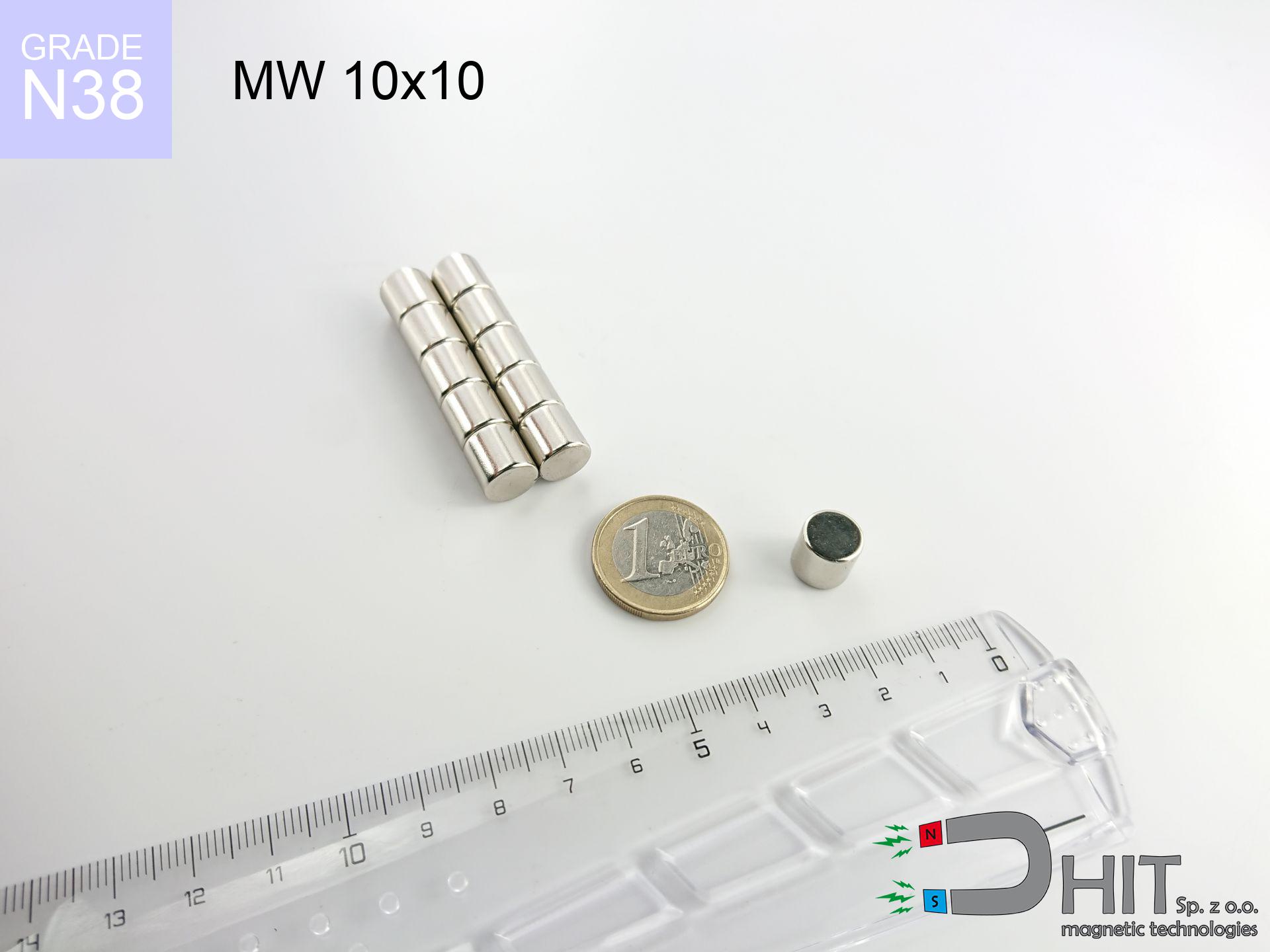
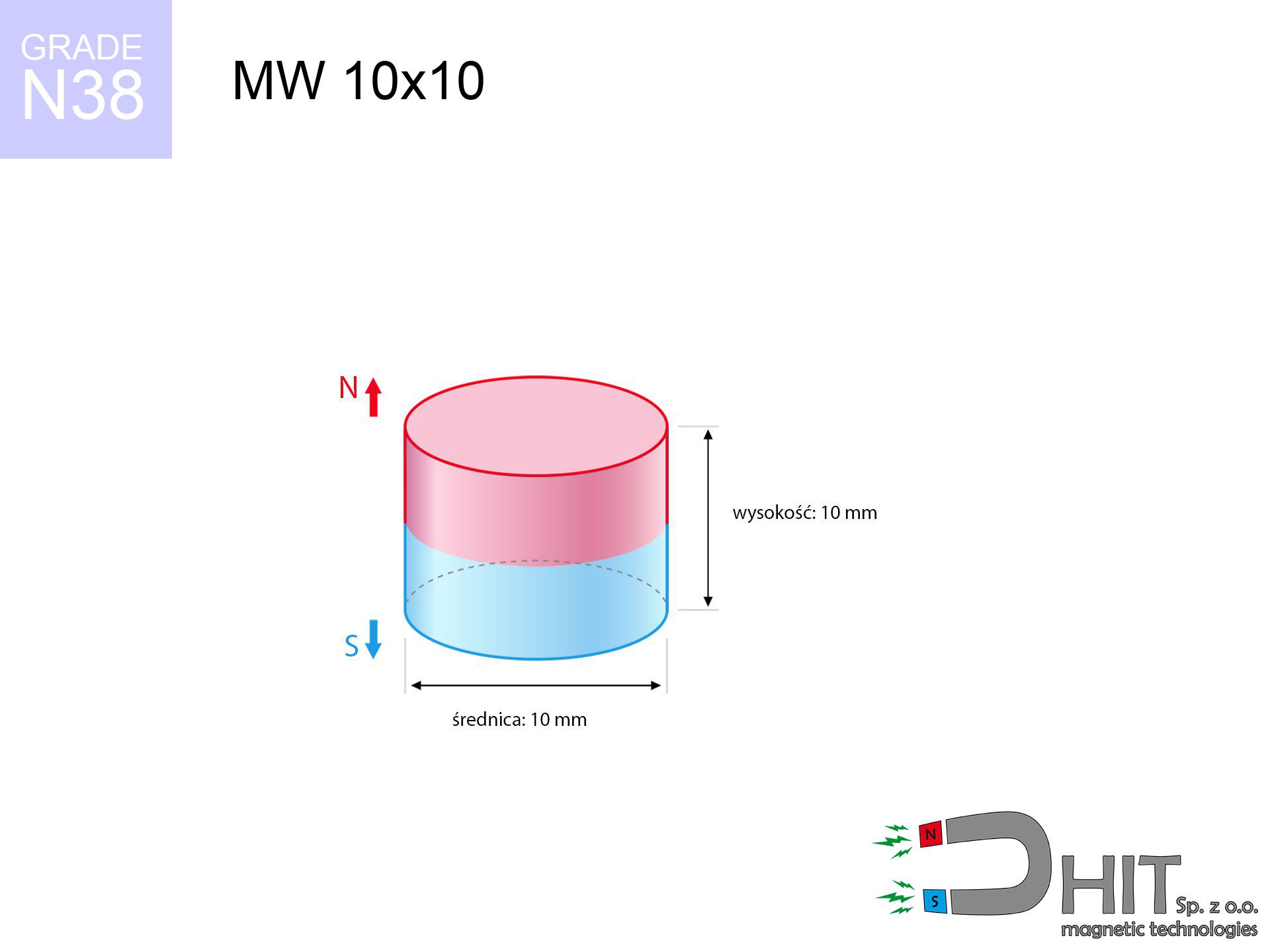
MW 10x10 / N38 - cylindrical magnet
cylindrical magnet
Catalog no 010004
GTIN/EAN: 5906301810032
- Diameter Ø
- 10 mm [±0,1 mm]
- Height
- 10 mm [±0,1 mm]
- Weight
- 5.89 g
- Magnetization Direction
- ↑ axial
- Coating
- [NiCuNi] Nickel
4.31 zł with VAT / pcs + price for transport
3.50 zł net + 23% VAT / pcs
bulk discounts:
Need more?Engineering report for this magnet
Full PDF analysis: pull and shear force, effect of distance, temperature and plate thickness, safety distances and the demagnetization curve.
Contact us by phone
+48 888 99 98 98
or get in touch by means of
inquiry form
the contact form page.
Parameters along with shape of a magnet can be analyzed using our
force calculator.
Same-day processing for orders placed before 14:00.
Technical - MW 10x10 / N38 - cylindrical magnet
Specification / characteristics - MW 10x10 / N38 - cylindrical magnet
| properties | values |
|---|---|
| Cat. no. | 010004 |
| GTIN/EAN | 5906301810032 |
| Production/Distribution | Dhit sp. z o.o. |
| Country of origin | Poland / China / Germany |
| Customs code | 85059029 |
| Diameter Ø | 10 mm [±0,1 mm] |
| Height | 10 mm [±0,1 mm] |
| Weight | 5.89 g |
| Magnetization Direction | ↑ axial |
| Load capacity ~ ? | 3.18 kg / 31.19 N |
| Magnetic Induction ~ ? | 553.84 mT / 5538 Gs |
| Coating | [NiCuNi] Nickel |
| Manufacturing Tolerance | ±0.1 mm |
Magnetic properties of material N38
| properties | values | units |
|---|---|---|
| remenance Br [min. - max.] ? | 12.2-12.6 | kGs |
| remenance Br [min. - max.] ? | 1220-1260 | mT |
| coercivity bHc ? | 10.8-11.5 | kOe |
| coercivity bHc ? | 860-915 | kA/m |
| actual internal force iHc | ≥ 12 | kOe |
| actual internal force iHc | ≥ 955 | kA/m |
| energy density [min. - max.] ? | 36-38 | BH max MGOe |
| energy density [min. - max.] ? | 287-303 | BH max KJ/m |
| max. temperature ? | ≤ 80 | °C |
Physical properties of sintered neodymium magnets Nd2Fe14B at 20°C
| properties | values | units |
|---|---|---|
| Vickers hardness | ≥550 | Hv |
| Density | ≥7.4 | g/cm3 |
| Curie Temperature TC | 312 - 380 | °C |
| Curie Temperature TF | 593 - 716 | °F |
| Specific resistance | 150 | μΩ⋅cm |
| Bending strength | 250 | MPa |
| Compressive strength | 1000~1100 | MPa |
| Thermal expansion parallel (∥) to orientation (M) | (3-4) x 10-6 | °C-1 |
| Thermal expansion perpendicular (⊥) to orientation (M) | -(1-3) x 10-6 | °C-1 |
| Young's modulus | 1.7 x 10⁴ | kg/mm² |
Physical simulation of the product - technical parameters
Presented information are the outcome of a mathematical analysis. Values were calculated on models for the class Nd2Fe14B. Real-world parameters may differ. Treat these calculations as a preliminary roadmap during assembly planning.
Table 1: Static pull force (pull vs gap) - interaction chart
MW 10x10 / N38
| Distance (mm) | Induction (Gauss) / mT | Pull Force (kg/lbs/g/N) | Risk Status |
|---|---|---|---|
| 0 mm |
5534 Gs
553.4 mT
|
3.18 kg / 7.01 LBS
3180.0 g / 31.2 N
|
warning |
| 1 mm |
4428 Gs
442.8 mT
|
2.04 kg / 4.49 LBS
2036.1 g / 20.0 N
|
warning |
| 2 mm |
3420 Gs
342.0 mT
|
1.21 kg / 2.68 LBS
1214.8 g / 11.9 N
|
low risk |
| 3 mm |
2597 Gs
259.7 mT
|
0.70 kg / 1.54 LBS
700.2 g / 6.9 N
|
low risk |
| 5 mm |
1498 Gs
149.8 mT
|
0.23 kg / 0.51 LBS
232.9 g / 2.3 N
|
low risk |
| 10 mm |
469 Gs
46.9 mT
|
0.02 kg / 0.05 LBS
22.9 g / 0.2 N
|
low risk |
| 15 mm |
198 Gs
19.8 mT
|
0.00 kg / 0.01 LBS
4.1 g / 0.0 N
|
low risk |
| 20 mm |
101 Gs
10.1 mT
|
0.00 kg / 0.00 LBS
1.1 g / 0.0 N
|
low risk |
| 30 mm |
36 Gs
3.6 mT
|
0.00 kg / 0.00 LBS
0.1 g / 0.0 N
|
low risk |
| 50 mm |
9 Gs
0.9 mT
|
0.00 kg / 0.00 LBS
0.0 g / 0.0 N
|
low risk |
Table 2: Shear load (vertical surface)
MW 10x10 / N38
| Distance (mm) | Friction coefficient | Pull Force (kg/lbs/g/N) |
|---|---|---|
| 0 mm | Stal (~0.2) |
0.64 kg / 1.40 LBS
636.0 g / 6.2 N
|
| 1 mm | Stal (~0.2) |
0.41 kg / 0.90 LBS
408.0 g / 4.0 N
|
| 2 mm | Stal (~0.2) |
0.24 kg / 0.53 LBS
242.0 g / 2.4 N
|
| 3 mm | Stal (~0.2) |
0.14 kg / 0.31 LBS
140.0 g / 1.4 N
|
| 5 mm | Stal (~0.2) |
0.05 kg / 0.10 LBS
46.0 g / 0.5 N
|
| 10 mm | Stal (~0.2) |
0.00 kg / 0.01 LBS
4.0 g / 0.0 N
|
| 15 mm | Stal (~0.2) |
0.00 kg / 0.00 LBS
0.0 g / 0.0 N
|
| 20 mm | Stal (~0.2) |
0.00 kg / 0.00 LBS
0.0 g / 0.0 N
|
| 30 mm | Stal (~0.2) |
0.00 kg / 0.00 LBS
0.0 g / 0.0 N
|
| 50 mm | Stal (~0.2) |
0.00 kg / 0.00 LBS
0.0 g / 0.0 N
|
Table 3: Wall mounting (shearing) - behavior on slippery surfaces
MW 10x10 / N38
| Surface type | Friction coefficient / % Mocy | Max load (kg/lbs/g/N) |
|---|---|---|
| Raw steel |
µ = 0.3
30% Nominalnej Siły
|
0.95 kg / 2.10 LBS
954.0 g / 9.4 N
|
| Painted steel (standard) |
µ = 0.2
20% Nominalnej Siły
|
0.64 kg / 1.40 LBS
636.0 g / 6.2 N
|
| Oily/slippery steel |
µ = 0.1
10% Nominalnej Siły
|
0.32 kg / 0.70 LBS
318.0 g / 3.1 N
|
| Magnet with anti-slip rubber |
µ = 0.5
50% Nominalnej Siły
|
1.59 kg / 3.51 LBS
1590.0 g / 15.6 N
|
Table 4: Material efficiency (saturation) - sheet metal selection
MW 10x10 / N38
| Steel thickness (mm) | % power | Real pull force (kg/lbs/g/N) |
|---|---|---|
| 0.5 mm |
|
0.32 kg / 0.70 LBS
318.0 g / 3.1 N
|
| 1 mm |
|
0.80 kg / 1.75 LBS
795.0 g / 7.8 N
|
| 2 mm |
|
1.59 kg / 3.51 LBS
1590.0 g / 15.6 N
|
| 3 mm |
|
2.39 kg / 5.26 LBS
2385.0 g / 23.4 N
|
| 5 mm |
|
3.18 kg / 7.01 LBS
3180.0 g / 31.2 N
|
| 10 mm |
|
3.18 kg / 7.01 LBS
3180.0 g / 31.2 N
|
| 11 mm |
|
3.18 kg / 7.01 LBS
3180.0 g / 31.2 N
|
| 12 mm |
|
3.18 kg / 7.01 LBS
3180.0 g / 31.2 N
|
Table 5: Thermal stability (material behavior) - power drop
MW 10x10 / N38
| Ambient temp. (°C) | Power loss | Remaining pull (kg/lbs/g/N) | Status |
|---|---|---|---|
| 20 °C | 0.0% |
3.18 kg / 7.01 LBS
3180.0 g / 31.2 N
|
OK |
| 40 °C | -2.2% |
3.11 kg / 6.86 LBS
3110.0 g / 30.5 N
|
OK |
| 60 °C | -4.4% |
3.04 kg / 6.70 LBS
3040.1 g / 29.8 N
|
OK |
| 80 °C | -6.6% |
2.97 kg / 6.55 LBS
2970.1 g / 29.1 N
|
|
| 100 °C | -28.8% |
2.26 kg / 4.99 LBS
2264.2 g / 22.2 N
|
Table 6: Magnet-Magnet interaction (repulsion) - forces in the system
MW 10x10 / N38
| Gap (mm) | Attraction (kg/lbs) (N-S) | Lateral Force (kg/lbs/g/N) | Repulsion (kg/lbs) (N-N) |
|---|---|---|---|
| 0 mm |
14.83 kg / 32.69 LBS
6 003 Gs
|
2.22 kg / 4.90 LBS
2224 g / 21.8 N
|
N/A |
| 1 mm |
12.01 kg / 26.48 LBS
9 962 Gs
|
1.80 kg / 3.97 LBS
1802 g / 17.7 N
|
10.81 kg / 23.83 LBS
~0 Gs
|
| 2 mm |
9.50 kg / 20.93 LBS
8 857 Gs
|
1.42 kg / 3.14 LBS
1424 g / 14.0 N
|
8.55 kg / 18.84 LBS
~0 Gs
|
| 3 mm |
7.38 kg / 16.27 LBS
7 809 Gs
|
1.11 kg / 2.44 LBS
1107 g / 10.9 N
|
6.64 kg / 14.64 LBS
~0 Gs
|
| 5 mm |
4.31 kg / 9.50 LBS
5 968 Gs
|
0.65 kg / 1.43 LBS
647 g / 6.3 N
|
3.88 kg / 8.55 LBS
~0 Gs
|
| 10 mm |
1.09 kg / 2.39 LBS
2 996 Gs
|
0.16 kg / 0.36 LBS
163 g / 1.6 N
|
0.98 kg / 2.16 LBS
~0 Gs
|
| 20 mm |
0.11 kg / 0.24 LBS
939 Gs
|
0.02 kg / 0.04 LBS
16 g / 0.2 N
|
0.10 kg / 0.21 LBS
~0 Gs
|
| 50 mm |
0.00 kg / 0.00 LBS
116 Gs
|
0.00 kg / 0.00 LBS
0 g / 0.0 N
|
0.00 kg / 0.00 LBS
~0 Gs
|
| 60 mm |
0.00 kg / 0.00 LBS
73 Gs
|
0.00 kg / 0.00 LBS
0 g / 0.0 N
|
0.00 kg / 0.00 LBS
~0 Gs
|
| 70 mm |
0.00 kg / 0.00 LBS
49 Gs
|
0.00 kg / 0.00 LBS
0 g / 0.0 N
|
0.00 kg / 0.00 LBS
~0 Gs
|
| 80 mm |
0.00 kg / 0.00 LBS
34 Gs
|
0.00 kg / 0.00 LBS
0 g / 0.0 N
|
0.00 kg / 0.00 LBS
~0 Gs
|
| 90 mm |
0.00 kg / 0.00 LBS
25 Gs
|
0.00 kg / 0.00 LBS
0 g / 0.0 N
|
0.00 kg / 0.00 LBS
~0 Gs
|
| 100 mm |
0.00 kg / 0.00 LBS
19 Gs
|
0.00 kg / 0.00 LBS
0 g / 0.0 N
|
0.00 kg / 0.00 LBS
~0 Gs
|
Table 7: Protective zones (implants) - precautionary measures
MW 10x10 / N38
| Object / Device | Limit (Gauss) / mT | Safe distance |
|---|---|---|
| Pacemaker | 5 Gs (0.5 mT) | 6.5 cm |
| Hearing aid | 10 Gs (1.0 mT) | 5.0 cm |
| Timepiece | 20 Gs (2.0 mT) | 4.0 cm |
| Mobile device | 40 Gs (4.0 mT) | 3.0 cm |
| Remote | 50 Gs (5.0 mT) | 3.0 cm |
| Payment card | 400 Gs (40.0 mT) | 1.5 cm |
| HDD hard drive | 600 Gs (60.0 mT) | 1.0 cm |
Table 8: Dynamics (kinetic energy) - collision effects
MW 10x10 / N38
| Start from (mm) | Speed (km/h) | Energy (J) | Predicted outcome |
|---|---|---|---|
| 10 mm |
16.62 km/h
(4.62 m/s)
|
0.06 J | |
| 30 mm |
16.70 km/h
(4.64 m/s)
|
0.06 J | |
| 50 mm |
16.71 km/h
(4.64 m/s)
|
0.06 J | |
| 100 mm |
16.71 km/h
(4.64 m/s)
|
0.06 J |
Table 9: Corrosion resistance
MW 10x10 / N38
| Technical parameter | Value / Description |
|---|---|
| Coating type | [NiCuNi] Nickel |
| Layer structure | Nickel - Copper - Nickel |
| Layer thickness | 10-20 µm |
| Salt spray test (SST) ? | 24 h |
| Recommended environment | Indoors only (dry) |
Table 10: Construction data (Flux)
MW 10x10 / N38
| Parameter | Value | SI Unit / Description |
|---|---|---|
| Magnetic Flux | 4 481 Mx | 44.8 µWb |
| Pc Coefficient | 0.89 | High (Stable) |
Table 11: Hydrostatics and buoyancy
MW 10x10 / N38
| Environment | Effective steel pull | Effect |
|---|---|---|
| Air (land) | 3.18 kg | Standard |
| Water (riverbed) |
3.64 kg
(+0.46 kg buoyancy gain)
|
+14.5% |
1. Wall mount (shear)
*Note: On a vertical surface, the magnet retains merely a fraction of its perpendicular strength.
2. Plate thickness effect
*Thin steel (e.g. computer case) severely limits the holding force.
3. Thermal stability
*For standard magnets, the safety limit is 80°C.
4. Demagnetization curve and operating point (B-H)
chart generated for the permeance coefficient Pc (Permeance Coefficient) = 0.89
This simulation demonstrates the magnetic stability of the selected magnet under specific geometric conditions. The solid red line represents the demagnetization curve (material potential), while the dashed blue line is the load line based on the magnet's geometry. The Pc (Permeance Coefficient), also known as the load line slope, is a dimensionless value that describes the relationship between the magnet's shape and its magnetic stability. The intersection of these two lines (the black dot) is the operating point — it determines the actual magnetic flux density generated by the magnet in this specific configuration. A higher Pc value means the magnet is more 'slender' (tall relative to its area), resulting in a higher operating point and better resistance to irreversible demagnetization caused by external fields or temperature. A value of 0.42 is relatively low (typical for flat magnets), meaning the operating point is closer to the 'knee' of the curve — caution is advised when operating at temperatures near the maximum limit to avoid strength loss.
Chemical composition
| iron (Fe) | 64% – 68% |
| neodymium (Nd) | 29% – 32% |
| boron (B) | 1.1% – 1.2% |
| dysprosium (Dy) | 0.5% – 2.0% |
| coating (Ni-Cu-Ni) | < 0.05% |
Environmental data
| recyclability (EoL) | 100% |
| recycled raw materials | ~10% (pre-cons) |
| carbon footprint | low / zredukowany |
| waste code (EWC) | 16 02 16 |
Other offers


![UMP 94x28 [3xM10] GW F300 GOLD / N38 - search holder](https://cdn3.dhit.pl/graphics/products/ump-94x28-m10-gw-f300-vux.jpg "UMP 94x28 [3xM10] GW F300 GOLD / N38 - search holder")
![UMP 94x40 [3xM10] GW F550 Silver Black / N52 - search holder](https://cdn3.dhit.pl/graphics/products/ump-94x40-3xm10-gw-f550-fad.jpg "UMP 94x40 [3xM10] GW F550 Silver Black / N52 - search holder")
Advantages and disadvantages of rare earth magnets.
Strengths
- They retain attractive force for nearly ten years – the drop is just ~1% (based on simulations),
- They are resistant to demagnetization induced by presence of other magnetic fields,
- The use of an elegant layer of noble metals (nickel, gold, silver) causes the element to be more visually attractive,
- Magnets possess excellent magnetic induction on the surface,
- Through (appropriate) combination of ingredients, they can achieve high thermal resistance, enabling action at temperatures approaching 230°C and above...
- Thanks to modularity in designing and the ability to adapt to individual projects,
- Universal use in future technologies – they serve a role in mass storage devices, motor assemblies, precision medical tools, as well as industrial machines.
- Thanks to concentrated force, small magnets offer high operating force, with minimal size,
Cons
- To avoid cracks upon strong impacts, we suggest using special steel holders. Such a solution protects the magnet and simultaneously increases its durability.
- Neodymium magnets lose their strength under the influence of heating. As soon as 80°C is exceeded, many of them start losing their force. Therefore, we recommend our special magnets marked [AH], which maintain durability even at temperatures up to 230°C
- When exposed to humidity, magnets usually rust. For applications outside, it is recommended to use protective magnets, such as magnets in rubber or plastics, which secure oxidation and corrosion.
- We suggest cover - magnetic holder, due to difficulties in realizing nuts inside the magnet and complex shapes.
- Potential hazard related to microscopic parts of magnets can be dangerous, if swallowed, which becomes key in the aspect of protecting the youngest. It is also worth noting that small components of these magnets are able to be problematic in diagnostics medical when they are in the body.
- Higher cost of purchase is a significant factor to consider compared to ceramic magnets, especially in budget applications
Pull force analysis
Maximum holding power of the magnet – what it depends on?
- with the application of a sheet made of low-carbon steel, ensuring maximum field concentration
- possessing a thickness of at least 10 mm to ensure full flux closure
- with an polished contact surface
- with zero gap (without coatings)
- under perpendicular force vector (90-degree angle)
- at conditions approx. 20°C
Lifting capacity in real conditions – factors
- Gap (between the magnet and the metal), as even a microscopic clearance (e.g. 0.5 mm) results in a drastic drop in lifting capacity by up to 50% (this also applies to paint, rust or dirt).
- Loading method – catalog parameter refers to detachment vertically. When slipping, the magnet exhibits much less (typically approx. 20-30% of maximum force).
- Wall thickness – thin material does not allow full use of the magnet. Magnetic flux penetrates through instead of generating force.
- Metal type – not every steel reacts the same. Alloy additives weaken the attraction effect.
- Surface finish – ideal contact is obtained only on smooth steel. Any scratches and bumps create air cushions, weakening the magnet.
- Temperature influence – hot environment weakens pulling force. Exceeding the limit temperature can permanently damage the magnet.
Holding force was tested on a smooth steel plate of 20 mm thickness, when a perpendicular force was applied, whereas under shearing force the holding force is lower. In addition, even a small distance between the magnet’s surface and the plate decreases the lifting capacity.
Precautions when working with NdFeB magnets
Danger to pacemakers
Patients with a ICD should maintain an large gap from magnets. The magnetic field can stop the operation of the implant.
Warning for allergy sufferers
Allergy Notice: The Ni-Cu-Ni coating contains nickel. If an allergic reaction happens, immediately stop handling magnets and wear gloves.
Hand protection
Pinching hazard: The pulling power is so great that it can result in blood blisters, pinching, and even bone fractures. Protective gloves are recommended.
Handling rules
Exercise caution. Rare earth magnets attract from a distance and connect with huge force, often quicker than you can react.
Electronic hazard
Avoid bringing magnets close to a purse, laptop, or screen. The magnetic field can destroy these devices and erase data from cards.
Maximum temperature
Do not overheat. NdFeB magnets are susceptible to heat. If you need operation above 80°C, look for HT versions (H, SH, UH).
Choking Hazard
Strictly keep magnets out of reach of children. Risk of swallowing is significant, and the effects of magnets clamping inside the body are tragic.
Eye protection
Watch out for shards. Magnets can explode upon violent connection, ejecting shards into the air. We recommend safety glasses.
Magnetic interference
A powerful magnetic field negatively affects the operation of compasses in smartphones and navigation systems. Keep magnets near a device to avoid breaking the sensors.
Fire risk
Fire hazard: Rare earth powder is highly flammable. Avoid machining magnets in home conditions as this risks ignition.
Tabela kosztu i czasu dostawy
Płatność przed wysyłką:

GLS kurier
Przesyłka będzie u Ciebie za 2-3 dni
14.99 ZŁ

InPost Paczkomaty 24/7
Przesyłka będzie u Ciebie za 1-2 dni
12.30 ZŁ
Płatność przy odbiorze (pobranie):
GLS kurier
Przesyłka będzie u Ciebie za 1-2 dni
23.00 ZŁ
Rate the product
Your rating