
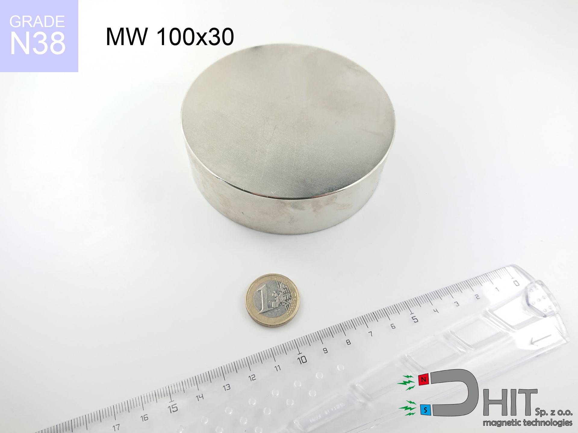
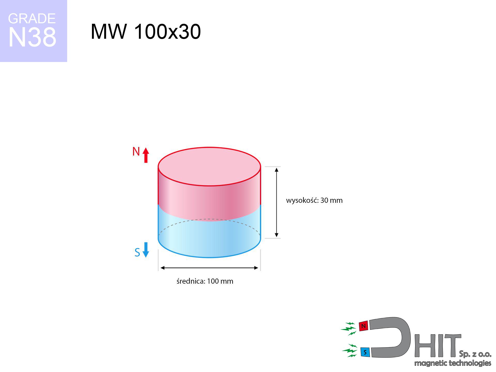
MW 100x30 / N38 - cylindrical magnet
cylindrical magnet
Catalog no 010002
GTIN/EAN: 5906301810025
Diameter Ø
100 mm [±0,1 mm]
Height
30 mm [±0,1 mm]
Weight
1767.15 g
Magnetization Direction
↑ axial
Load capacity
215.17 kg / 2110.78 N
Magnetic Induction
318.96 mT / 3190 Gs
Coating
[NiCuNi] Nickel
650.01 ZŁ with VAT / pcs + price for transport
528.46 ZŁ net + 23% VAT / pcs
bulk discounts:
Need more?
Pick up the phone and ask
+48 22 499 98 98
or contact us through
form
the contact page.
Force and shape of a magnet can be calculated with our
magnetic mass calculator.
Orders placed before 14:00 will be shipped the same business day.
Detailed specification - MW 100x30 / N38 - cylindrical magnet
Specification / characteristics - MW 100x30 / N38 - cylindrical magnet
| properties | values |
|---|---|
| Cat. no. | 010002 |
| GTIN/EAN | 5906301810025 |
| Production/Distribution | Dhit sp. z o.o. |
| Country of origin | Poland / China / Germany |
| Customs code | 85059029 |
| Diameter Ø | 100 mm [±0,1 mm] |
| Height | 30 mm [±0,1 mm] |
| Weight | 1767.15 g |
| Magnetization Direction | ↑ axial |
| Load capacity ~ ? | 215.17 kg / 2110.78 N |
| Magnetic Induction ~ ? | 318.96 mT / 3190 Gs |
| Coating | [NiCuNi] Nickel |
| Manufacturing Tolerance | ±0.1 mm |
Magnetic properties of material N38
| properties | values | units |
|---|---|---|
| remenance Br [min. - max.] ? | 12.2-12.6 | kGs |
| remenance Br [min. - max.] ? | 1220-1260 | mT |
| coercivity bHc ? | 10.8-11.5 | kOe |
| coercivity bHc ? | 860-915 | kA/m |
| actual internal force iHc | ≥ 12 | kOe |
| actual internal force iHc | ≥ 955 | kA/m |
| energy density [min. - max.] ? | 36-38 | BH max MGOe |
| energy density [min. - max.] ? | 287-303 | BH max KJ/m |
| max. temperature ? | ≤ 80 | °C |
Physical properties of sintered neodymium magnets Nd2Fe14B at 20°C
| properties | values | units |
|---|---|---|
| Vickers hardness | ≥550 | Hv |
| Density | ≥7.4 | g/cm3 |
| Curie Temperature TC | 312 - 380 | °C |
| Curie Temperature TF | 593 - 716 | °F |
| Specific resistance | 150 | μΩ⋅cm |
| Bending strength | 250 | MPa |
| Compressive strength | 1000~1100 | MPa |
| Thermal expansion parallel (∥) to orientation (M) | (3-4) x 10-6 | °C-1 |
| Thermal expansion perpendicular (⊥) to orientation (M) | -(1-3) x 10-6 | °C-1 |
| Young's modulus | 1.7 x 10⁴ | kg/mm² |
Engineering analysis of the product - technical parameters
Presented information are the result of a physical analysis. Values are based on models for the material Nd2Fe14B. Real-world performance might slightly differ from theoretical values. Use these calculations as a supplementary guide during assembly planning.
Table 1: Static force (force vs distance) - characteristics
MW 100x30 / N38
| Distance (mm) | Induction (Gauss) / mT | Pull Force (kg/lbs/g/N) | Risk Status |
|---|---|---|---|
| 0 mm |
3189 Gs
318.9 mT
|
215.17 kg / 474.37 pounds
215170.0 g / 2110.8 N
|
crushing |
| 1 mm |
3143 Gs
314.3 mT
|
208.96 kg / 460.68 pounds
208959.6 g / 2049.9 N
|
crushing |
| 2 mm |
3094 Gs
309.4 mT
|
202.53 kg / 446.51 pounds
202531.7 g / 1986.8 N
|
crushing |
| 3 mm |
3044 Gs
304.4 mT
|
195.98 kg / 432.07 pounds
195982.5 g / 1922.6 N
|
crushing |
| 5 mm |
2939 Gs
293.9 mT
|
182.65 kg / 402.68 pounds
182651.7 g / 1791.8 N
|
crushing |
| 10 mm |
2657 Gs
265.7 mT
|
149.35 kg / 329.26 pounds
149349.8 g / 1465.1 N
|
crushing |
| 15 mm |
2366 Gs
236.6 mT
|
118.41 kg / 261.05 pounds
118412.6 g / 1161.6 N
|
crushing |
| 20 mm |
2081 Gs
208.1 mT
|
91.64 kg / 202.03 pounds
91640.5 g / 899.0 N
|
crushing |
| 30 mm |
1573 Gs
157.3 mT
|
52.34 kg / 115.40 pounds
52344.5 g / 513.5 N
|
crushing |
| 50 mm |
874 Gs
87.4 mT
|
16.14 kg / 35.58 pounds
16140.3 g / 158.3 N
|
crushing |
Table 2: Shear hold (wall)
MW 100x30 / N38
| Distance (mm) | Friction coefficient | Pull Force (kg/lbs/g/N) |
|---|---|---|
| 0 mm | Stal (~0.2) |
43.03 kg / 94.87 pounds
43034.0 g / 422.2 N
|
| 1 mm | Stal (~0.2) |
41.79 kg / 92.14 pounds
41792.0 g / 410.0 N
|
| 2 mm | Stal (~0.2) |
40.51 kg / 89.30 pounds
40506.0 g / 397.4 N
|
| 3 mm | Stal (~0.2) |
39.20 kg / 86.41 pounds
39196.0 g / 384.5 N
|
| 5 mm | Stal (~0.2) |
36.53 kg / 80.53 pounds
36530.0 g / 358.4 N
|
| 10 mm | Stal (~0.2) |
29.87 kg / 65.85 pounds
29870.0 g / 293.0 N
|
| 15 mm | Stal (~0.2) |
23.68 kg / 52.21 pounds
23682.0 g / 232.3 N
|
| 20 mm | Stal (~0.2) |
18.33 kg / 40.41 pounds
18328.0 g / 179.8 N
|
| 30 mm | Stal (~0.2) |
10.47 kg / 23.08 pounds
10468.0 g / 102.7 N
|
| 50 mm | Stal (~0.2) |
3.23 kg / 7.12 pounds
3228.0 g / 31.7 N
|
Table 3: Wall mounting (sliding) - vertical pull
MW 100x30 / N38
| Surface type | Friction coefficient / % Mocy | Max load (kg/lbs/g/N) |
|---|---|---|
| Raw steel |
µ = 0.3
30% Nominalnej Siły
|
64.55 kg / 142.31 pounds
64551.0 g / 633.2 N
|
| Painted steel (standard) |
µ = 0.2
20% Nominalnej Siły
|
43.03 kg / 94.87 pounds
43034.0 g / 422.2 N
|
| Oily/slippery steel |
µ = 0.1
10% Nominalnej Siły
|
21.52 kg / 47.44 pounds
21517.0 g / 211.1 N
|
| Magnet with anti-slip rubber |
µ = 0.5
50% Nominalnej Siły
|
107.59 kg / 237.18 pounds
107585.0 g / 1055.4 N
|
Table 4: Steel thickness (substrate influence) - power losses
MW 100x30 / N38
| Steel thickness (mm) | % power | Real pull force (kg/lbs/g/N) |
|---|---|---|
| 0.5 mm |
|
7.17 kg / 15.81 pounds
7172.3 g / 70.4 N
|
| 1 mm |
|
17.93 kg / 39.53 pounds
17930.8 g / 175.9 N
|
| 2 mm |
|
35.86 kg / 79.06 pounds
35861.7 g / 351.8 N
|
| 3 mm |
|
53.79 kg / 118.59 pounds
53792.5 g / 527.7 N
|
| 5 mm |
|
89.65 kg / 197.65 pounds
89654.2 g / 879.5 N
|
| 10 mm |
|
179.31 kg / 395.31 pounds
179308.3 g / 1759.0 N
|
| 11 mm |
|
197.24 kg / 434.84 pounds
197239.2 g / 1934.9 N
|
| 12 mm |
|
215.17 kg / 474.37 pounds
215170.0 g / 2110.8 N
|
Table 5: Thermal resistance (material behavior) - thermal limit
MW 100x30 / N38
| Ambient temp. (°C) | Power loss | Remaining pull (kg/lbs/g/N) | Status |
|---|---|---|---|
| 20 °C | 0.0% |
215.17 kg / 474.37 pounds
215170.0 g / 2110.8 N
|
OK |
| 40 °C | -2.2% |
210.44 kg / 463.93 pounds
210436.3 g / 2064.4 N
|
OK |
| 60 °C | -4.4% |
205.70 kg / 453.50 pounds
205702.5 g / 2017.9 N
|
|
| 80 °C | -6.6% |
200.97 kg / 443.06 pounds
200968.8 g / 1971.5 N
|
|
| 100 °C | -28.8% |
153.20 kg / 337.75 pounds
153201.0 g / 1502.9 N
|
Table 6: Magnet-Magnet interaction (repulsion) - field range
MW 100x30 / N38
| Gap (mm) | Attraction (kg/lbs) (N-S) | Shear Strength (kg/lbs/g/N) | Repulsion (kg/lbs) (N-N) |
|---|---|---|---|
| 0 mm |
492.55 kg / 1085.88 pounds
4 762 Gs
|
73.88 kg / 162.88 pounds
73882 g / 724.8 N
|
N/A |
| 1 mm |
485.56 kg / 1070.47 pounds
6 333 Gs
|
72.83 kg / 160.57 pounds
72834 g / 714.5 N
|
437.00 kg / 963.42 pounds
~0 Gs
|
| 2 mm |
478.33 kg / 1054.54 pounds
6 286 Gs
|
71.75 kg / 158.18 pounds
71749 g / 703.9 N
|
430.50 kg / 949.08 pounds
~0 Gs
|
| 3 mm |
471.01 kg / 1038.40 pounds
6 238 Gs
|
70.65 kg / 155.76 pounds
70652 g / 693.1 N
|
423.91 kg / 934.56 pounds
~0 Gs
|
| 5 mm |
456.15 kg / 1005.64 pounds
6 139 Gs
|
68.42 kg / 150.85 pounds
68422 g / 671.2 N
|
410.53 kg / 905.07 pounds
~0 Gs
|
| 10 mm |
418.11 kg / 921.77 pounds
5 877 Gs
|
62.72 kg / 138.27 pounds
62716 g / 615.2 N
|
376.30 kg / 829.59 pounds
~0 Gs
|
| 20 mm |
341.88 kg / 753.71 pounds
5 314 Gs
|
51.28 kg / 113.06 pounds
51282 g / 503.1 N
|
307.69 kg / 678.34 pounds
~0 Gs
|
| 50 mm |
159.49 kg / 351.61 pounds
3 630 Gs
|
23.92 kg / 52.74 pounds
23923 g / 234.7 N
|
143.54 kg / 316.45 pounds
~0 Gs
|
| 60 mm |
119.82 kg / 264.16 pounds
3 146 Gs
|
17.97 kg / 39.62 pounds
17973 g / 176.3 N
|
107.84 kg / 237.75 pounds
~0 Gs
|
| 70 mm |
89.40 kg / 197.09 pounds
2 718 Gs
|
13.41 kg / 29.56 pounds
13410 g / 131.6 N
|
80.46 kg / 177.38 pounds
~0 Gs
|
| 80 mm |
66.51 kg / 146.64 pounds
2 344 Gs
|
9.98 kg / 22.00 pounds
9977 g / 97.9 N
|
59.86 kg / 131.97 pounds
~0 Gs
|
| 90 mm |
49.50 kg / 109.14 pounds
2 022 Gs
|
7.43 kg / 16.37 pounds
7426 g / 72.8 N
|
44.55 kg / 98.22 pounds
~0 Gs
|
| 100 mm |
36.95 kg / 81.45 pounds
1 747 Gs
|
5.54 kg / 12.22 pounds
5542 g / 54.4 N
|
33.25 kg / 73.31 pounds
~0 Gs
|
Table 7: Hazards (electronics) - precautionary measures
MW 100x30 / N38
| Object / Device | Limit (Gauss) / mT | Safe distance |
|---|---|---|
| Pacemaker | 5 Gs (0.5 mT) | 44.0 cm |
| Hearing aid | 10 Gs (1.0 mT) | 34.5 cm |
| Timepiece | 20 Gs (2.0 mT) | 27.0 cm |
| Mobile device | 40 Gs (4.0 mT) | 21.0 cm |
| Remote | 50 Gs (5.0 mT) | 19.0 cm |
| Payment card | 400 Gs (40.0 mT) | 8.0 cm |
| HDD hard drive | 600 Gs (60.0 mT) | 6.5 cm |
Table 8: Collisions (cracking risk) - warning
MW 100x30 / N38
| Start from (mm) | Speed (km/h) | Energy (J) | Predicted outcome |
|---|---|---|---|
| 10 mm |
15.21 km/h
(4.22 m/s)
|
15.77 J | |
| 30 mm |
22.01 km/h
(6.11 m/s)
|
33.03 J | |
| 50 mm |
26.02 km/h
(7.23 m/s)
|
46.17 J | |
| 100 mm |
35.32 km/h
(9.81 m/s)
|
85.04 J |
Table 9: Corrosion resistance
MW 100x30 / N38
| Technical parameter | Value / Description |
|---|---|
| Coating type | [NiCuNi] Nickel |
| Layer structure | Nickel - Copper - Nickel |
| Layer thickness | 10-20 µm |
| Salt spray test (SST) ? | 24 h |
| Recommended environment | Indoors only (dry) |
Table 10: Construction data (Pc)
MW 100x30 / N38
| Parameter | Value | SI Unit / Description |
|---|---|---|
| Magnetic Flux | 269 425 Mx | 2694.3 µWb |
| Pc Coefficient | 0.40 | Low (Flat) |
Table 11: Submerged application
MW 100x30 / N38
| Environment | Effective steel pull | Effect |
|---|---|---|
| Air (land) | 215.17 kg | Standard |
| Water (riverbed) |
246.37 kg
(+31.20 kg buoyancy gain)
|
+14.5% |
1. Sliding resistance
*Warning: On a vertical wall, the magnet retains merely ~20% of its nominal pull.
2. Steel saturation
*Thin metal sheet (e.g. computer case) severely reduces the holding force.
3. Power loss vs temp
*For N38 grade, the critical limit is 80°C.
4. Demagnetization curve and operating point (B-H)
chart generated for the permeance coefficient Pc (Permeance Coefficient) = 0.40
This simulation demonstrates the magnetic stability of the selected magnet under specific geometric conditions. The solid red line represents the demagnetization curve (material potential), while the dashed blue line is the load line based on the magnet's geometry. The Pc (Permeance Coefficient), also known as the load line slope, is a dimensionless value that describes the relationship between the magnet's shape and its magnetic stability. The intersection of these two lines (the black dot) is the operating point — it determines the actual magnetic flux density generated by the magnet in this specific configuration. A higher Pc value means the magnet is more 'slender' (tall relative to its area), resulting in a higher operating point and better resistance to irreversible demagnetization caused by external fields or temperature. A value of 0.42 is relatively low (typical for flat magnets), meaning the operating point is closer to the 'knee' of the curve — caution is advised when operating at temperatures near the maximum limit to avoid strength loss.
Material specification
| iron (Fe) | 64% – 68% |
| neodymium (Nd) | 29% – 32% |
| boron (B) | 1.1% – 1.2% |
| dysprosium (Dy) | 0.5% – 2.0% |
| coating (Ni-Cu-Ni) | < 0.05% |
Sustainability
| recyclability (EoL) | 100% |
| recycled raw materials | ~10% (pre-cons) |
| carbon footprint | low / zredukowany |
| waste code (EWC) | 16 02 16 |
View also deals

![UI 39x9x7 [BA] - badge holder](https://cdn3.dhit.pl/graphics/products/ui39x9x7-dav.jpg "UI 39x9x7 [BA] - badge holder")
![UMH 25x8x45 [M5] / N38 - magnetic holder with hook](https://cdn3.dhit.pl/graphics/products/umh-25x8x45-m5-cep.jpg "UMH 25x8x45 [M5] / N38 - magnetic holder with hook")

Pros and cons of neodymium magnets.
Benefits
- Their power remains stable, and after approximately ten years it drops only by ~1% (according to research),
- They are resistant to demagnetization induced by external field influence,
- In other words, due to the reflective layer of gold, the element gains a professional look,
- They feature high magnetic induction at the operating surface, which increases their power,
- Through (adequate) combination of ingredients, they can achieve high thermal resistance, allowing for action at temperatures approaching 230°C and above...
- Thanks to versatility in forming and the capacity to modify to specific needs,
- Key role in high-tech industry – they find application in data components, drive modules, advanced medical instruments, also multitasking production systems.
- Thanks to efficiency per cm³, small magnets offer high operating force, occupying minimum space,
Weaknesses
- They are prone to damage upon too strong impacts. To avoid cracks, it is worth protecting magnets in a protective case. Such protection not only protects the magnet but also improves its resistance to damage
- NdFeB magnets demagnetize when exposed to high temperatures. After reaching 80°C, many of them experience permanent drop of power (a factor is the shape and dimensions of the magnet). We offer magnets specially adapted to work at temperatures up to 230°C marked [AH], which are very resistant to heat
- Due to the susceptibility of magnets to corrosion in a humid environment, we suggest using waterproof magnets made of rubber, plastic or other material resistant to moisture, in case of application outdoors
- We suggest a housing - magnetic mount, due to difficulties in producing nuts inside the magnet and complicated shapes.
- Possible danger resulting from small fragments of magnets are risky, when accidentally swallowed, which becomes key in the context of child safety. Additionally, tiny parts of these devices can disrupt the diagnostic process medical after entering the body.
- Due to neodymium price, their price is higher than average,
Holding force characteristics
Highest magnetic holding force – what contributes to it?
- on a plate made of structural steel, effectively closing the magnetic flux
- with a cross-section of at least 10 mm
- with a surface free of scratches
- with total lack of distance (without impurities)
- during pulling in a direction perpendicular to the mounting surface
- in temp. approx. 20°C
Practical lifting capacity: influencing factors
- Gap between magnet and steel – even a fraction of a millimeter of separation (caused e.g. by veneer or dirt) significantly weakens the pulling force, often by half at just 0.5 mm.
- Loading method – declared lifting capacity refers to detachment vertically. When slipping, the magnet exhibits much less (typically approx. 20-30% of nominal force).
- Metal thickness – the thinner the sheet, the weaker the hold. Magnetic flux penetrates through instead of generating force.
- Steel grade – ideal substrate is high-permeability steel. Cast iron may attract less.
- Surface finish – ideal contact is obtained only on smooth steel. Rough texture create air cushions, reducing force.
- Temperature – heating the magnet results in weakening of force. It is worth remembering the thermal limit for a given model.
Lifting capacity was assessed by applying a steel plate with a smooth surface of suitable thickness (min. 20 mm), under vertically applied force, whereas under attempts to slide the magnet the lifting capacity is smaller. Moreover, even a slight gap between the magnet and the plate decreases the holding force.
Safety rules for work with neodymium magnets
Implant safety
Health Alert: Strong magnets can deactivate pacemakers and defibrillators. Do not approach if you have electronic implants.
Adults only
Only for adults. Tiny parts can be swallowed, causing serious injuries. Keep away from kids and pets.
Dust explosion hazard
Mechanical processing of neodymium magnets carries a risk of fire hazard. Neodymium dust reacts violently with oxygen and is hard to extinguish.
Electronic hazard
Avoid bringing magnets close to a purse, laptop, or TV. The magnetism can destroy these devices and wipe information from cards.
Crushing risk
Pinching hazard: The attraction force is so immense that it can result in hematomas, crushing, and even bone fractures. Use thick gloves.
Shattering risk
Despite metallic appearance, neodymium is delicate and not impact-resistant. Avoid impacts, as the magnet may shatter into hazardous fragments.
Nickel coating and allergies
Warning for allergy sufferers: The nickel-copper-nickel coating contains nickel. If an allergic reaction appears, cease handling magnets and wear gloves.
Caution required
Handle magnets with awareness. Their huge power can shock even experienced users. Be vigilant and do not underestimate their force.
Permanent damage
Keep cool. Neodymium magnets are susceptible to heat. If you need operation above 80°C, ask us about special high-temperature series (H, SH, UH).
Phone sensors
Remember: neodymium magnets generate a field that disrupts sensitive sensors. Maintain a separation from your mobile, device, and navigation systems.
Tabela kosztu i czasu dostawy
Płatność przed wysyłką:

GLS kurier
Przesyłka będzie u Ciebie za 2-3 dni
14.99 ZŁ

InPost Paczkomaty 24/7
Przesyłka będzie u Ciebie za 1-2 dni
12.30 ZŁ
Płatność przy odbiorze (pobranie):
GLS kurier
Przesyłka będzie u Ciebie za 1-2 dni
23.00 ZŁ
Rate the product
Your rating