

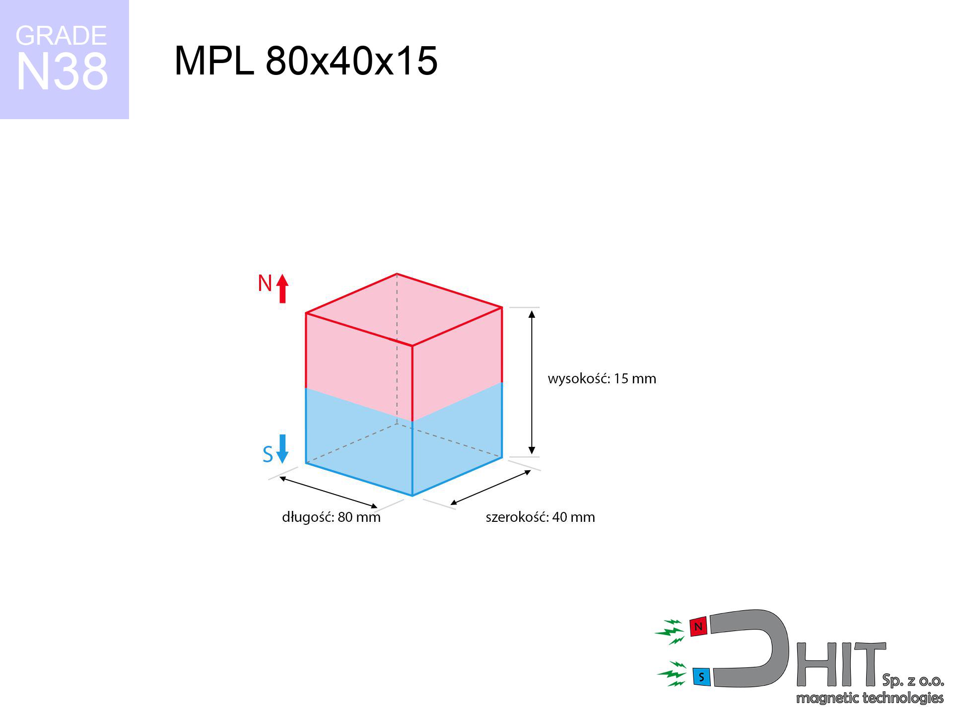
MPL 80x40x15 / N38 - lamellar magnet
lamellar magnet
Catalog no 020177
GTIN/EAN: 5906301811831
length
80 mm [±0,1 mm]
Width
40 mm [±0,1 mm]
Height
15 mm [±0,1 mm]
Weight
360 g
Magnetization Direction
↑ axial
Load capacity
73.57 kg / 721.75 N
Magnetic Induction
285.78 mT / 2858 Gs
Coating
[NiCuNi] Nickel
139.54 ZŁ with VAT / pcs + price for transport
113.45 ZŁ net + 23% VAT / pcs
bulk discounts:
Need more?
Give us a call
+48 888 99 98 98
otherwise send us a note through
our online form
the contact form page.
Specifications along with appearance of magnetic components can be estimated with our
magnetic mass calculator.
Same-day shipping for orders placed before 14:00.
Technical details - MPL 80x40x15 / N38 - lamellar magnet
Specification / characteristics - MPL 80x40x15 / N38 - lamellar magnet
| properties | values |
|---|---|
| Cat. no. | 020177 |
| GTIN/EAN | 5906301811831 |
| Production/Distribution | Dhit sp. z o.o. |
| Country of origin | Poland / China / Germany |
| Customs code | 85059029 |
| length | 80 mm [±0,1 mm] |
| Width | 40 mm [±0,1 mm] |
| Height | 15 mm [±0,1 mm] |
| Weight | 360 g |
| Magnetization Direction | ↑ axial |
| Load capacity ~ ? | 73.57 kg / 721.75 N |
| Magnetic Induction ~ ? | 285.78 mT / 2858 Gs |
| Coating | [NiCuNi] Nickel |
| Manufacturing Tolerance | ±0.1 mm |
Magnetic properties of material N38
| properties | values | units |
|---|---|---|
| remenance Br [min. - max.] ? | 12.2-12.6 | kGs |
| remenance Br [min. - max.] ? | 1220-1260 | mT |
| coercivity bHc ? | 10.8-11.5 | kOe |
| coercivity bHc ? | 860-915 | kA/m |
| actual internal force iHc | ≥ 12 | kOe |
| actual internal force iHc | ≥ 955 | kA/m |
| energy density [min. - max.] ? | 36-38 | BH max MGOe |
| energy density [min. - max.] ? | 287-303 | BH max KJ/m |
| max. temperature ? | ≤ 80 | °C |
Physical properties of sintered neodymium magnets Nd2Fe14B at 20°C
| properties | values | units |
|---|---|---|
| Vickers hardness | ≥550 | Hv |
| Density | ≥7.4 | g/cm3 |
| Curie Temperature TC | 312 - 380 | °C |
| Curie Temperature TF | 593 - 716 | °F |
| Specific resistance | 150 | μΩ⋅cm |
| Bending strength | 250 | MPa |
| Compressive strength | 1000~1100 | MPa |
| Thermal expansion parallel (∥) to orientation (M) | (3-4) x 10-6 | °C-1 |
| Thermal expansion perpendicular (⊥) to orientation (M) | -(1-3) x 10-6 | °C-1 |
| Young's modulus | 1.7 x 10⁴ | kg/mm² |
Technical modeling of the product - report
Presented values represent the outcome of a engineering simulation. Results rely on models for the material Nd2Fe14B. Real-world parameters may differ from theoretical values. Treat these data as a supplementary guide when designing systems.
Table 1: Static force (force vs gap) - characteristics
MPL 80x40x15 / N38
| Distance (mm) | Induction (Gauss) / mT | Pull Force (kg/lbs/g/N) | Risk Status |
|---|---|---|---|
| 0 mm |
2857 Gs
285.7 mT
|
73.57 kg / 162.19 pounds
73570.0 g / 721.7 N
|
crushing |
| 1 mm |
2778 Gs
277.8 mT
|
69.55 kg / 153.32 pounds
69546.1 g / 682.2 N
|
crushing |
| 2 mm |
2693 Gs
269.3 mT
|
65.33 kg / 144.03 pounds
65331.2 g / 640.9 N
|
crushing |
| 3 mm |
2603 Gs
260.3 mT
|
61.05 kg / 134.59 pounds
61047.5 g / 598.9 N
|
crushing |
| 5 mm |
2415 Gs
241.5 mT
|
52.56 kg / 115.87 pounds
52559.7 g / 515.6 N
|
crushing |
| 10 mm |
1943 Gs
194.3 mT
|
34.02 kg / 75.00 pounds
34021.1 g / 333.7 N
|
crushing |
| 15 mm |
1527 Gs
152.7 mT
|
21.01 kg / 46.31 pounds
21007.7 g / 206.1 N
|
crushing |
| 20 mm |
1192 Gs
119.2 mT
|
12.81 kg / 28.24 pounds
12808.1 g / 125.6 N
|
crushing |
| 30 mm |
736 Gs
73.6 mT
|
4.89 kg / 10.77 pounds
4886.6 g / 47.9 N
|
warning |
| 50 mm |
313 Gs
31.3 mT
|
0.88 kg / 1.95 pounds
884.8 g / 8.7 N
|
low risk |
Table 2: Vertical force (vertical surface)
MPL 80x40x15 / N38
| Distance (mm) | Friction coefficient | Pull Force (kg/lbs/g/N) |
|---|---|---|
| 0 mm | Stal (~0.2) |
14.71 kg / 32.44 pounds
14714.0 g / 144.3 N
|
| 1 mm | Stal (~0.2) |
13.91 kg / 30.67 pounds
13910.0 g / 136.5 N
|
| 2 mm | Stal (~0.2) |
13.07 kg / 28.81 pounds
13066.0 g / 128.2 N
|
| 3 mm | Stal (~0.2) |
12.21 kg / 26.92 pounds
12210.0 g / 119.8 N
|
| 5 mm | Stal (~0.2) |
10.51 kg / 23.17 pounds
10512.0 g / 103.1 N
|
| 10 mm | Stal (~0.2) |
6.80 kg / 15.00 pounds
6804.0 g / 66.7 N
|
| 15 mm | Stal (~0.2) |
4.20 kg / 9.26 pounds
4202.0 g / 41.2 N
|
| 20 mm | Stal (~0.2) |
2.56 kg / 5.65 pounds
2562.0 g / 25.1 N
|
| 30 mm | Stal (~0.2) |
0.98 kg / 2.16 pounds
978.0 g / 9.6 N
|
| 50 mm | Stal (~0.2) |
0.18 kg / 0.39 pounds
176.0 g / 1.7 N
|
Table 3: Wall mounting (sliding) - vertical pull
MPL 80x40x15 / N38
| Surface type | Friction coefficient / % Mocy | Max load (kg/lbs/g/N) |
|---|---|---|
| Raw steel |
µ = 0.3
30% Nominalnej Siły
|
22.07 kg / 48.66 pounds
22071.0 g / 216.5 N
|
| Painted steel (standard) |
µ = 0.2
20% Nominalnej Siły
|
14.71 kg / 32.44 pounds
14714.0 g / 144.3 N
|
| Oily/slippery steel |
µ = 0.1
10% Nominalnej Siły
|
7.36 kg / 16.22 pounds
7357.0 g / 72.2 N
|
| Magnet with anti-slip rubber |
µ = 0.5
50% Nominalnej Siły
|
36.79 kg / 81.10 pounds
36785.0 g / 360.9 N
|
Table 4: Steel thickness (substrate influence) - power losses
MPL 80x40x15 / N38
| Steel thickness (mm) | % power | Real pull force (kg/lbs/g/N) |
|---|---|---|
| 0.5 mm |
|
2.45 kg / 5.41 pounds
2452.3 g / 24.1 N
|
| 1 mm |
|
6.13 kg / 13.52 pounds
6130.8 g / 60.1 N
|
| 2 mm |
|
12.26 kg / 27.03 pounds
12261.7 g / 120.3 N
|
| 3 mm |
|
18.39 kg / 40.55 pounds
18392.5 g / 180.4 N
|
| 5 mm |
|
30.65 kg / 67.58 pounds
30654.2 g / 300.7 N
|
| 10 mm |
|
61.31 kg / 135.16 pounds
61308.3 g / 601.4 N
|
| 11 mm |
|
67.44 kg / 148.68 pounds
67439.2 g / 661.6 N
|
| 12 mm |
|
73.57 kg / 162.19 pounds
73570.0 g / 721.7 N
|
Table 5: Thermal stability (material behavior) - power drop
MPL 80x40x15 / N38
| Ambient temp. (°C) | Power loss | Remaining pull (kg/lbs/g/N) | Status |
|---|---|---|---|
| 20 °C | 0.0% |
73.57 kg / 162.19 pounds
73570.0 g / 721.7 N
|
OK |
| 40 °C | -2.2% |
71.95 kg / 158.63 pounds
71951.5 g / 705.8 N
|
OK |
| 60 °C | -4.4% |
70.33 kg / 155.06 pounds
70332.9 g / 690.0 N
|
|
| 80 °C | -6.6% |
68.71 kg / 151.49 pounds
68714.4 g / 674.1 N
|
|
| 100 °C | -28.8% |
52.38 kg / 115.48 pounds
52381.8 g / 513.9 N
|
Table 6: Magnet-Magnet interaction (repulsion) - forces in the system
MPL 80x40x15 / N38
| Gap (mm) | Attraction (kg/lbs) (N-S) | Sliding Force (kg/lbs/g/N) | Repulsion (kg/lbs) (N-N) |
|---|---|---|---|
| 0 mm |
161.08 kg / 355.13 pounds
4 384 Gs
|
24.16 kg / 53.27 pounds
24163 g / 237.0 N
|
N/A |
| 1 mm |
156.77 kg / 345.63 pounds
5 638 Gs
|
23.52 kg / 51.84 pounds
23516 g / 230.7 N
|
141.10 kg / 311.07 pounds
~0 Gs
|
| 2 mm |
152.27 kg / 335.70 pounds
5 556 Gs
|
22.84 kg / 50.36 pounds
22841 g / 224.1 N
|
137.05 kg / 302.13 pounds
~0 Gs
|
| 3 mm |
147.69 kg / 325.60 pounds
5 472 Gs
|
22.15 kg / 48.84 pounds
22153 g / 217.3 N
|
132.92 kg / 293.04 pounds
~0 Gs
|
| 5 mm |
138.36 kg / 305.04 pounds
5 297 Gs
|
20.75 kg / 45.76 pounds
20754 g / 203.6 N
|
124.53 kg / 274.53 pounds
~0 Gs
|
| 10 mm |
115.08 kg / 253.71 pounds
4 830 Gs
|
17.26 kg / 38.06 pounds
17262 g / 169.3 N
|
103.57 kg / 228.34 pounds
~0 Gs
|
| 20 mm |
74.49 kg / 164.22 pounds
3 886 Gs
|
11.17 kg / 24.63 pounds
11174 g / 109.6 N
|
67.04 kg / 147.80 pounds
~0 Gs
|
| 50 mm |
17.20 kg / 37.91 pounds
1 867 Gs
|
2.58 kg / 5.69 pounds
2580 g / 25.3 N
|
15.48 kg / 34.12 pounds
~0 Gs
|
| 60 mm |
10.70 kg / 23.59 pounds
1 473 Gs
|
1.60 kg / 3.54 pounds
1605 g / 15.7 N
|
9.63 kg / 21.23 pounds
~0 Gs
|
| 70 mm |
6.78 kg / 14.94 pounds
1 172 Gs
|
1.02 kg / 2.24 pounds
1017 g / 10.0 N
|
6.10 kg / 13.45 pounds
~0 Gs
|
| 80 mm |
4.38 kg / 9.65 pounds
942 Gs
|
0.66 kg / 1.45 pounds
657 g / 6.4 N
|
3.94 kg / 8.69 pounds
~0 Gs
|
| 90 mm |
2.89 kg / 6.36 pounds
765 Gs
|
0.43 kg / 0.95 pounds
433 g / 4.2 N
|
2.60 kg / 5.72 pounds
~0 Gs
|
| 100 mm |
1.94 kg / 4.27 pounds
627 Gs
|
0.29 kg / 0.64 pounds
291 g / 2.9 N
|
1.74 kg / 3.84 pounds
~0 Gs
|
Table 7: Hazards (implants) - precautionary measures
MPL 80x40x15 / N38
| Object / Device | Limit (Gauss) / mT | Safe distance |
|---|---|---|
| Pacemaker | 5 Gs (0.5 mT) | 26.0 cm |
| Hearing aid | 10 Gs (1.0 mT) | 20.5 cm |
| Timepiece | 20 Gs (2.0 mT) | 16.0 cm |
| Mobile device | 40 Gs (4.0 mT) | 12.5 cm |
| Car key | 50 Gs (5.0 mT) | 11.5 cm |
| Payment card | 400 Gs (40.0 mT) | 4.5 cm |
| HDD hard drive | 600 Gs (60.0 mT) | 3.5 cm |
Table 8: Collisions (cracking risk) - warning
MPL 80x40x15 / N38
| Start from (mm) | Speed (km/h) | Energy (J) | Predicted outcome |
|---|---|---|---|
| 10 mm |
18.11 km/h
(5.03 m/s)
|
4.56 J | |
| 30 mm |
25.99 km/h
(7.22 m/s)
|
9.38 J | |
| 50 mm |
32.48 km/h
(9.02 m/s)
|
14.65 J | |
| 100 mm |
45.61 km/h
(12.67 m/s)
|
28.89 J |
Table 9: Coating parameters (durability)
MPL 80x40x15 / N38
| Technical parameter | Value / Description |
|---|---|
| Coating type | [NiCuNi] Nickel |
| Layer structure | Nickel - Copper - Nickel |
| Layer thickness | 10-20 µm |
| Salt spray test (SST) ? | 24 h |
| Recommended environment | Indoors only (dry) |
Table 10: Electrical data (Pc)
MPL 80x40x15 / N38
| Parameter | Value | SI Unit / Description |
|---|---|---|
| Magnetic Flux | 94 833 Mx | 948.3 µWb |
| Pc Coefficient | 0.33 | Low (Flat) |
Table 11: Underwater work (magnet fishing)
MPL 80x40x15 / N38
| Environment | Effective steel pull | Effect |
|---|---|---|
| Air (land) | 73.57 kg | Standard |
| Water (riverbed) |
84.24 kg
(+10.67 kg buoyancy gain)
|
+14.5% |
1. Shear force
*Warning: On a vertical wall, the magnet holds only approx. 20-30% of its nominal pull.
2. Steel thickness impact
*Thin steel (e.g. computer case) significantly weakens the holding force.
3. Thermal stability
*For N38 grade, the safety limit is 80°C.
4. Demagnetization curve and operating point (B-H)
chart generated for the permeance coefficient Pc (Permeance Coefficient) = 0.33
This simulation demonstrates the magnetic stability of the selected magnet under specific geometric conditions. The solid red line represents the demagnetization curve (material potential), while the dashed blue line is the load line based on the magnet's geometry. The Pc (Permeance Coefficient), also known as the load line slope, is a dimensionless value that describes the relationship between the magnet's shape and its magnetic stability. The intersection of these two lines (the black dot) is the operating point — it determines the actual magnetic flux density generated by the magnet in this specific configuration. A higher Pc value means the magnet is more 'slender' (tall relative to its area), resulting in a higher operating point and better resistance to irreversible demagnetization caused by external fields or temperature. A value of 0.42 is relatively low (typical for flat magnets), meaning the operating point is closer to the 'knee' of the curve — caution is advised when operating at temperatures near the maximum limit to avoid strength loss.
Elemental analysis
| iron (Fe) | 64% – 68% |
| neodymium (Nd) | 29% – 32% |
| boron (B) | 1.1% – 1.2% |
| dysprosium (Dy) | 0.5% – 2.0% |
| coating (Ni-Cu-Ni) | < 0.05% |
Environmental data
| recyclability (EoL) | 100% |
| recycled raw materials | ~10% (pre-cons) |
| carbon footprint | low / zredukowany |
| waste code (EWC) | 16 02 16 |
Check out also products
![SM 32x175 [2xM8] / N42 - magnetic separator](https://cdn3.dhit.pl/graphics/products/sm-32x175-2xm8-tej.jpg "SM 32x175 [2xM8] / N42 - magnetic separator")


![BM 750x180x70 [4x M8] - magnetic beam](https://cdn3.dhit.pl/graphics/products/bm-750x180x70-4x-m8-zif.jpg "BM 750x180x70 [4x M8] - magnetic beam")
Advantages and disadvantages of rare earth magnets.
Pros
- They do not lose magnetism, even during approximately 10 years – the reduction in power is only ~1% (theoretically),
- They have excellent resistance to magnetic field loss when exposed to external fields,
- A magnet with a metallic silver surface has an effective appearance,
- They feature high magnetic induction at the operating surface, which increases their power,
- Thanks to resistance to high temperature, they are able to function (depending on the form) even at temperatures up to 230°C and higher...
- Thanks to modularity in constructing and the capacity to adapt to specific needs,
- Key role in modern technologies – they serve a role in magnetic memories, electric drive systems, medical equipment, also industrial machines.
- Relatively small size with high pulling force – neodymium magnets offer impressive pulling force in compact dimensions, which makes them useful in compact constructions
Disadvantages
- At strong impacts they can break, therefore we recommend placing them in steel cases. A metal housing provides additional protection against damage and increases the magnet's durability.
- Neodymium magnets lose their force under the influence of heating. As soon as 80°C is exceeded, many of them start losing their force. Therefore, we recommend our special magnets marked [AH], which maintain durability even at temperatures up to 230°C
- Due to the susceptibility of magnets to corrosion in a humid environment, we advise using waterproof magnets made of rubber, plastic or other material resistant to moisture, when using outdoors
- We recommend casing - magnetic mechanism, due to difficulties in creating threads inside the magnet and complex forms.
- Possible danger to health – tiny shards of magnets can be dangerous, when accidentally swallowed, which is particularly important in the aspect of protecting the youngest. Additionally, small components of these products can disrupt the diagnostic process medical after entering the body.
- High unit price – neodymium magnets are more expensive than other types of magnets (e.g. ferrite), which hinders application in large quantities
Holding force characteristics
Detachment force of the magnet in optimal conditions – what it depends on?
- using a plate made of low-carbon steel, acting as a magnetic yoke
- possessing a thickness of minimum 10 mm to ensure full flux closure
- with a plane free of scratches
- under conditions of no distance (metal-to-metal)
- under axial force vector (90-degree angle)
- in stable room temperature
Key elements affecting lifting force
- Air gap (betwixt the magnet and the plate), because even a microscopic clearance (e.g. 0.5 mm) results in a drastic drop in force by up to 50% (this also applies to varnish, corrosion or debris).
- Load vector – maximum parameter is available only during pulling at a 90° angle. The resistance to sliding of the magnet along the surface is usually several times lower (approx. 1/5 of the lifting capacity).
- Metal thickness – thin material does not allow full use of the magnet. Magnetic flux passes through the material instead of generating force.
- Steel grade – ideal substrate is high-permeability steel. Hardened steels may have worse magnetic properties.
- Surface structure – the smoother and more polished the surface, the better the adhesion and stronger the hold. Unevenness creates an air distance.
- Operating temperature – neodymium magnets have a sensitivity to temperature. At higher temperatures they lose power, and at low temperatures they can be stronger (up to a certain limit).
Holding force was measured on the plate surface of 20 mm thickness, when a perpendicular force was applied, however under shearing force the lifting capacity is smaller. Moreover, even a slight gap between the magnet and the plate lowers the lifting capacity.
Safe handling of NdFeB magnets
Do not overheat magnets
Monitor thermal conditions. Heating the magnet above 80 degrees Celsius will ruin its magnetic structure and pulling force.
Keep away from computers
Powerful magnetic fields can erase data on credit cards, HDDs, and storage devices. Keep a distance of at least 10 cm.
Respect the power
Be careful. Neodymium magnets attract from a long distance and snap with huge force, often quicker than you can move away.
Dust explosion hazard
Fire hazard: Rare earth powder is highly flammable. Avoid machining magnets in home conditions as this risks ignition.
Material brittleness
Beware of splinters. Magnets can fracture upon violent connection, launching shards into the air. We recommend safety glasses.
Implant safety
People with a ICD have to maintain an safe separation from magnets. The magnetism can interfere with the operation of the implant.
Precision electronics
Remember: neodymium magnets generate a field that disrupts precision electronics. Keep a separation from your phone, tablet, and GPS.
Allergic reactions
Warning for allergy sufferers: The Ni-Cu-Ni coating contains nickel. If an allergic reaction occurs, cease working with magnets and use protective gear.
Swallowing risk
Only for adults. Tiny parts pose a choking risk, causing serious injuries. Store away from kids and pets.
Crushing risk
Big blocks can break fingers instantly. Never place your hand betwixt two attracting surfaces.
Tabela kosztu i czasu dostawy
Płatność przed wysyłką:

GLS kurier
Przesyłka będzie u Ciebie za 2-3 dni
14.99 ZŁ

InPost Paczkomaty 24/7
Przesyłka będzie u Ciebie za 1-2 dni
12.30 ZŁ
Płatność przy odbiorze (pobranie):
GLS kurier
Przesyłka będzie u Ciebie za 1-2 dni
23.00 ZŁ
Rate the product
Your rating