
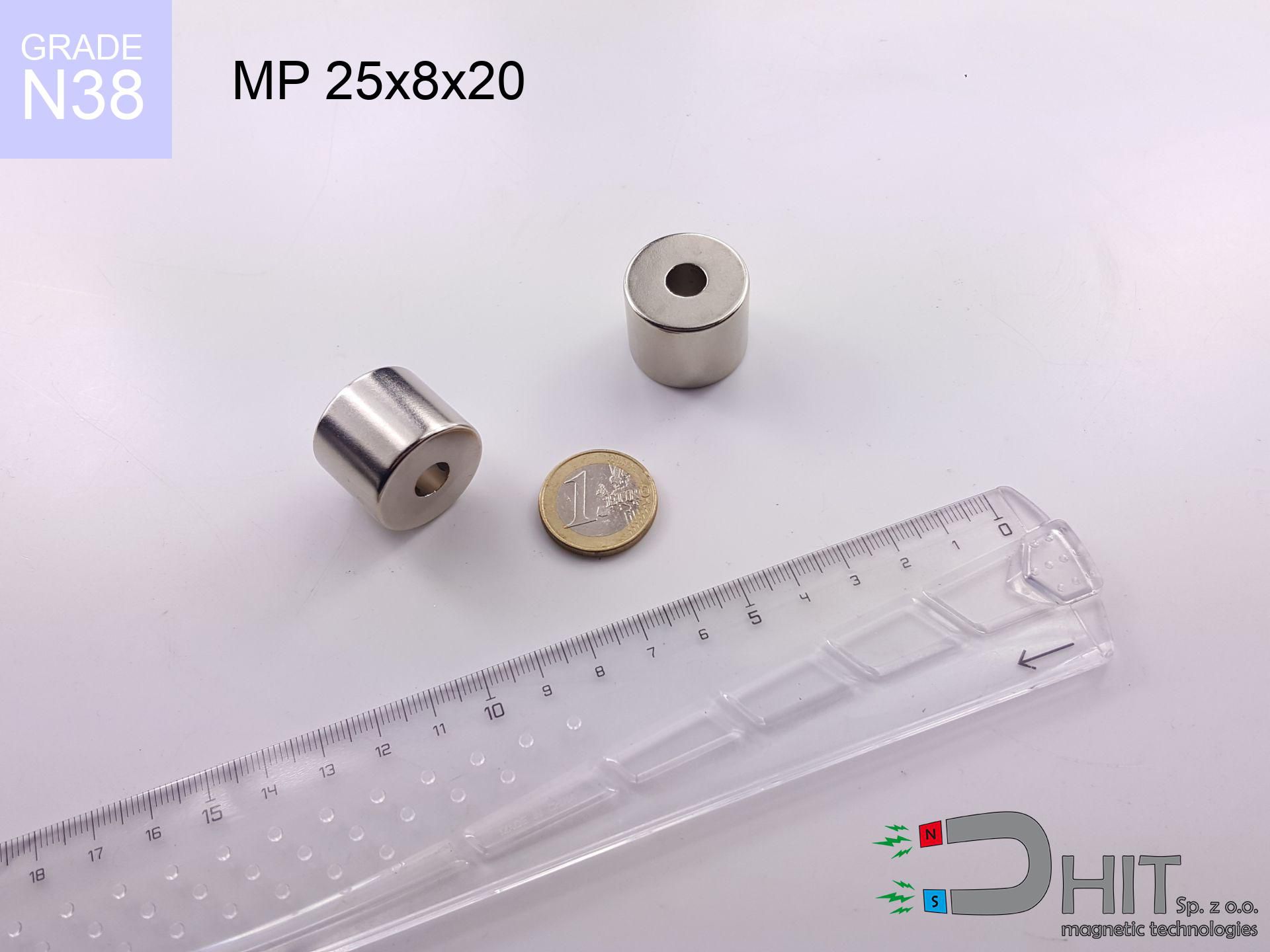
MP 25x8x20 / N38 - ring magnet
ring magnet
Catalog no 030450
GTIN/EAN: 5906301812340
- Diameter
- 25 mm [±0,1 mm]
- internal diameter Ø
- 8 mm [±0,1 mm]
- Height
- 20 mm [±0,1 mm]
- Weight
- 66.09 g
- Magnetization Direction
- ↑ axial
- Coating
- [NiCuNi] Nickel
41.71 zł with VAT / pcs + price for transport
33.91 zł net + 23% VAT / pcs
bulk discounts:
Need more?Engineering report for this magnet
Full PDF analysis: pull and shear force, effect of distance, temperature and plate thickness, safety distances and the demagnetization curve.
Give us a call
+48 888 99 98 98
or drop us a message using
our online form
our website.
Specifications and shape of neodymium magnets can be tested with our
force calculator.
Orders placed before 14:00 will be shipped the same business day.
Technical parameters of the product - MP 25x8x20 / N38 - ring magnet
Specification / characteristics - MP 25x8x20 / N38 - ring magnet
| properties | values |
|---|---|
| Cat. no. | 030450 |
| GTIN/EAN | 5906301812340 |
| Production/Distribution | Dhit sp. z o.o. |
| Country of origin | Poland / China / Germany |
| Customs code | 85059029 |
| Diameter | 25 mm [±0,1 mm] |
| internal diameter Ø | 8 mm [±0,1 mm] |
| Height | 20 mm [±0,1 mm] |
| Weight | 66.09 g |
| Magnetization Direction | ↑ axial |
| Load capacity ~ ? | 19.02 kg / 186.54 N |
| Magnetic Induction ~ ? | 525.50 mT / 5255 Gs |
| Coating | [NiCuNi] Nickel |
| Manufacturing Tolerance | ±0.1 mm |
Magnetic properties of material N38
| properties | values | units |
|---|---|---|
| remenance Br [min. - max.] ? | 12.2-12.6 | kGs |
| remenance Br [min. - max.] ? | 1220-1260 | mT |
| coercivity bHc ? | 10.8-11.5 | kOe |
| coercivity bHc ? | 860-915 | kA/m |
| actual internal force iHc | ≥ 12 | kOe |
| actual internal force iHc | ≥ 955 | kA/m |
| energy density [min. - max.] ? | 36-38 | BH max MGOe |
| energy density [min. - max.] ? | 287-303 | BH max KJ/m |
| max. temperature ? | ≤ 80 | °C |
Physical properties of sintered neodymium magnets Nd2Fe14B at 20°C
| properties | values | units |
|---|---|---|
| Vickers hardness | ≥550 | Hv |
| Density | ≥7.4 | g/cm3 |
| Curie Temperature TC | 312 - 380 | °C |
| Curie Temperature TF | 593 - 716 | °F |
| Specific resistance | 150 | μΩ⋅cm |
| Bending strength | 250 | MPa |
| Compressive strength | 1000~1100 | MPa |
| Thermal expansion parallel (∥) to orientation (M) | (3-4) x 10-6 | °C-1 |
| Thermal expansion perpendicular (⊥) to orientation (M) | -(1-3) x 10-6 | °C-1 |
| Young's modulus | 1.7 x 10⁴ | kg/mm² |
Engineering modeling of the magnet - technical parameters
These information constitute the result of a engineering analysis. Results were calculated on algorithms for the class Nd2Fe14B. Operational parameters might slightly differ. Treat these calculations as a supplementary guide for designers.
Table 1: Static force (pull vs distance) - interaction chart
MP 25x8x20 / N38
| Distance (mm) | Induction (Gauss) / mT | Pull Force (kg/lbs/g/N) | Risk Status |
|---|---|---|---|
| 0 mm |
5777 Gs
577.7 mT
|
19.02 kg / 41.93 pounds
19020.0 g / 186.6 N
|
crushing |
| 1 mm |
5310 Gs
531.0 mT
|
16.07 kg / 35.42 pounds
16067.7 g / 157.6 N
|
crushing |
| 2 mm |
4846 Gs
484.6 mT
|
13.38 kg / 29.50 pounds
13380.1 g / 131.3 N
|
crushing |
| 3 mm |
4397 Gs
439.7 mT
|
11.02 kg / 24.29 pounds
11019.3 g / 108.1 N
|
crushing |
| 5 mm |
3576 Gs
357.6 mT
|
7.29 kg / 16.07 pounds
7287.1 g / 71.5 N
|
strong |
| 10 mm |
2073 Gs
207.3 mT
|
2.45 kg / 5.40 pounds
2448.1 g / 24.0 N
|
strong |
| 15 mm |
1231 Gs
123.1 mT
|
0.86 kg / 1.90 pounds
863.8 g / 8.5 N
|
safe |
| 20 mm |
773 Gs
77.3 mT
|
0.34 kg / 0.75 pounds
340.1 g / 3.3 N
|
safe |
| 30 mm |
356 Gs
35.6 mT
|
0.07 kg / 0.16 pounds
72.1 g / 0.7 N
|
safe |
| 50 mm |
115 Gs
11.5 mT
|
0.01 kg / 0.02 pounds
7.5 g / 0.1 N
|
safe |
Table 2: Shear force (wall)
MP 25x8x20 / N38
| Distance (mm) | Friction coefficient | Pull Force (kg/lbs/g/N) |
|---|---|---|
| 0 mm | Stal (~0.2) |
3.80 kg / 8.39 pounds
3804.0 g / 37.3 N
|
| 1 mm | Stal (~0.2) |
3.21 kg / 7.09 pounds
3214.0 g / 31.5 N
|
| 2 mm | Stal (~0.2) |
2.68 kg / 5.90 pounds
2676.0 g / 26.3 N
|
| 3 mm | Stal (~0.2) |
2.20 kg / 4.86 pounds
2204.0 g / 21.6 N
|
| 5 mm | Stal (~0.2) |
1.46 kg / 3.21 pounds
1458.0 g / 14.3 N
|
| 10 mm | Stal (~0.2) |
0.49 kg / 1.08 pounds
490.0 g / 4.8 N
|
| 15 mm | Stal (~0.2) |
0.17 kg / 0.38 pounds
172.0 g / 1.7 N
|
| 20 mm | Stal (~0.2) |
0.07 kg / 0.15 pounds
68.0 g / 0.7 N
|
| 30 mm | Stal (~0.2) |
0.01 kg / 0.03 pounds
14.0 g / 0.1 N
|
| 50 mm | Stal (~0.2) |
0.00 kg / 0.00 pounds
2.0 g / 0.0 N
|
Table 3: Wall mounting (sliding) - behavior on slippery surfaces
MP 25x8x20 / N38
| Surface type | Friction coefficient / % Mocy | Max load (kg/lbs/g/N) |
|---|---|---|
| Raw steel |
µ = 0.3
30% Nominalnej Siły
|
5.71 kg / 12.58 pounds
5706.0 g / 56.0 N
|
| Painted steel (standard) |
µ = 0.2
20% Nominalnej Siły
|
3.80 kg / 8.39 pounds
3804.0 g / 37.3 N
|
| Oily/slippery steel |
µ = 0.1
10% Nominalnej Siły
|
1.90 kg / 4.19 pounds
1902.0 g / 18.7 N
|
| Magnet with anti-slip rubber |
µ = 0.5
50% Nominalnej Siły
|
9.51 kg / 20.97 pounds
9510.0 g / 93.3 N
|
Table 4: Steel thickness (substrate influence) - power losses
MP 25x8x20 / N38
| Steel thickness (mm) | % power | Real pull force (kg/lbs/g/N) |
|---|---|---|
| 0.5 mm |
|
0.95 kg / 2.10 pounds
951.0 g / 9.3 N
|
| 1 mm |
|
2.38 kg / 5.24 pounds
2377.5 g / 23.3 N
|
| 2 mm |
|
4.76 kg / 10.48 pounds
4755.0 g / 46.6 N
|
| 3 mm |
|
7.13 kg / 15.72 pounds
7132.5 g / 70.0 N
|
| 5 mm |
|
11.89 kg / 26.21 pounds
11887.5 g / 116.6 N
|
| 10 mm |
|
19.02 kg / 41.93 pounds
19020.0 g / 186.6 N
|
| 11 mm |
|
19.02 kg / 41.93 pounds
19020.0 g / 186.6 N
|
| 12 mm |
|
19.02 kg / 41.93 pounds
19020.0 g / 186.6 N
|
Table 5: Working in heat (material behavior) - power drop
MP 25x8x20 / N38
| Ambient temp. (°C) | Power loss | Remaining pull (kg/lbs/g/N) | Status |
|---|---|---|---|
| 20 °C | 0.0% |
19.02 kg / 41.93 pounds
19020.0 g / 186.6 N
|
OK |
| 40 °C | -2.2% |
18.60 kg / 41.01 pounds
18601.6 g / 182.5 N
|
OK |
| 60 °C | -4.4% |
18.18 kg / 40.09 pounds
18183.1 g / 178.4 N
|
OK |
| 80 °C | -6.6% |
17.76 kg / 39.16 pounds
17764.7 g / 174.3 N
|
|
| 100 °C | -28.8% |
13.54 kg / 29.86 pounds
13542.2 g / 132.8 N
|
Table 6: Magnet-Magnet interaction (repulsion) - field collision
MP 25x8x20 / N38
| Gap (mm) | Attraction (kg/lbs) (N-S) | Shear Force (kg/lbs/g/N) | Repulsion (kg/lbs) (N-N) |
|---|---|---|---|
| 0 mm |
30.91 kg / 68.14 pounds
6 082 Gs
|
4.64 kg / 10.22 pounds
4636 g / 45.5 N
|
N/A |
| 1 mm |
28.48 kg / 62.79 pounds
11 091 Gs
|
4.27 kg / 9.42 pounds
4272 g / 41.9 N
|
25.63 kg / 56.51 pounds
~0 Gs
|
| 2 mm |
26.11 kg / 57.57 pounds
10 620 Gs
|
3.92 kg / 8.63 pounds
3917 g / 38.4 N
|
23.50 kg / 51.81 pounds
~0 Gs
|
| 3 mm |
23.86 kg / 52.61 pounds
10 153 Gs
|
3.58 kg / 7.89 pounds
3580 g / 35.1 N
|
21.48 kg / 47.35 pounds
~0 Gs
|
| 5 mm |
19.76 kg / 43.56 pounds
9 238 Gs
|
2.96 kg / 6.53 pounds
2964 g / 29.1 N
|
17.78 kg / 39.20 pounds
~0 Gs
|
| 10 mm |
11.84 kg / 26.11 pounds
7 152 Gs
|
1.78 kg / 3.92 pounds
1776 g / 17.4 N
|
10.66 kg / 23.50 pounds
~0 Gs
|
| 20 mm |
3.98 kg / 8.77 pounds
4 145 Gs
|
0.60 kg / 1.32 pounds
597 g / 5.9 N
|
3.58 kg / 7.89 pounds
~0 Gs
|
| 50 mm |
0.24 kg / 0.54 pounds
1 024 Gs
|
0.04 kg / 0.08 pounds
36 g / 0.4 N
|
0.22 kg / 0.48 pounds
~0 Gs
|
| 60 mm |
0.12 kg / 0.26 pounds
712 Gs
|
0.02 kg / 0.04 pounds
18 g / 0.2 N
|
0.11 kg / 0.23 pounds
~0 Gs
|
| 70 mm |
0.06 kg / 0.13 pounds
514 Gs
|
0.01 kg / 0.02 pounds
9 g / 0.1 N
|
0.06 kg / 0.12 pounds
~0 Gs
|
| 80 mm |
0.03 kg / 0.07 pounds
383 Gs
|
0.01 kg / 0.01 pounds
5 g / 0.1 N
|
0.03 kg / 0.07 pounds
~0 Gs
|
| 90 mm |
0.02 kg / 0.04 pounds
293 Gs
|
0.00 kg / 0.01 pounds
3 g / 0.0 N
|
0.02 kg / 0.04 pounds
~0 Gs
|
| 100 mm |
0.01 kg / 0.03 pounds
230 Gs
|
0.00 kg / 0.00 pounds
2 g / 0.0 N
|
0.01 kg / 0.02 pounds
~0 Gs
|
Table 7: Hazards (implants) - warnings
MP 25x8x20 / N38
| Object / Device | Limit (Gauss) / mT | Safe distance |
|---|---|---|
| Pacemaker | 5 Gs (0.5 mT) | 17.0 cm |
| Hearing aid | 10 Gs (1.0 mT) | 13.5 cm |
| Timepiece | 20 Gs (2.0 mT) | 10.5 cm |
| Mobile device | 40 Gs (4.0 mT) | 8.0 cm |
| Remote | 50 Gs (5.0 mT) | 7.5 cm |
| Payment card | 400 Gs (40.0 mT) | 3.0 cm |
| HDD hard drive | 600 Gs (60.0 mT) | 2.5 cm |
Table 8: Dynamics (cracking risk) - warning
MP 25x8x20 / N38
| Start from (mm) | Speed (km/h) | Energy (J) | Predicted outcome |
|---|---|---|---|
| 10 mm |
18.05 km/h
(5.01 m/s)
|
0.83 J | |
| 30 mm |
19.29 km/h
(5.36 m/s)
|
0.95 J | |
| 50 mm |
19.34 km/h
(5.37 m/s)
|
0.95 J | |
| 100 mm |
19.35 km/h
(5.38 m/s)
|
0.95 J |
Table 9: Surface protection spec
MP 25x8x20 / N38
| Technical parameter | Value / Description |
|---|---|
| Coating type | [NiCuNi] Nickel |
| Layer structure | Nickel - Copper - Nickel |
| Layer thickness | 10-20 µm |
| Salt spray test (SST) ? | 24 h |
| Recommended environment | Indoors only (dry) |
Table 10: Construction data (Flux)
MP 25x8x20 / N38
| Parameter | Value | SI Unit / Description |
|---|---|---|
| Magnetic Flux | 10 108 Mx | 101.1 µWb |
| Pc Coefficient | 1.25 | High (Stable) |
Table 11: Physics of underwater searching
MP 25x8x20 / N38
| Environment | Effective steel pull | Effect |
|---|---|---|
| Air (land) | 19.02 kg | Standard |
| Water (riverbed) |
21.78 kg
(+2.76 kg buoyancy gain)
|
+14.5% |
1. Wall mount (shear)
*Note: On a vertical surface, the magnet retains only ~20% of its max power.
2. Efficiency vs thickness
*Thin steel (e.g. computer case) drastically limits the holding force.
3. Thermal stability
*For N38 material, the critical limit is 80°C.
4. Demagnetization curve and operating point (B-H)
chart generated for the permeance coefficient Pc (Permeance Coefficient) = 1.25
The chart above illustrates the magnetic characteristics of the material within the second quadrant of the hysteresis loop. The solid red line represents the demagnetization curve (material potential), while the dashed blue line is the load line based on the magnet's geometry. The Pc (Permeance Coefficient), also known as the load line slope, is a dimensionless value that describes the relationship between the magnet's shape and its magnetic stability. The intersection of these two lines (the black dot) is the operating point — it determines the actual magnetic flux density generated by the magnet in this specific configuration. A higher Pc value means the magnet is more 'slender' (tall relative to its area), resulting in a higher operating point and better resistance to irreversible demagnetization caused by external fields or temperature. A value of 0.42 is relatively low (typical for flat magnets), meaning the operating point is closer to the 'knee' of the curve — caution is advised when operating at temperatures near the maximum limit to avoid strength loss.
Material specification
| iron (Fe) | 64% – 68% |
| neodymium (Nd) | 29% – 32% |
| boron (B) | 1.1% – 1.2% |
| dysprosium (Dy) | 0.5% – 2.0% |
| coating (Ni-Cu-Ni) | < 0.05% |
Sustainability
| recyclability (EoL) | 100% |
| recycled raw materials | ~10% (pre-cons) |
| carbon footprint | low / zredukowany |
| waste code (EWC) | 16 02 16 |
Check out more offers

![SM 25x175 [2xM8] / N42 - magnetic separator](https://cdn3.dhit.pl/graphics/products/sm-25x175-2xm8-fux.jpg "SM 25x175 [2xM8] / N42 - magnetic separator")


Pros as well as cons of neodymium magnets.
Strengths
- They have unchanged lifting capacity, and over more than 10 years their performance decreases symbolically – ~1% (in testing),
- They maintain their magnetic properties even under strong external field,
- A magnet with a shiny gold surface has better aesthetics,
- Magnetic induction on the surface of the magnet turns out to be exceptional,
- Neodymium magnets are characterized by extremely high magnetic induction on the magnet surface and are able to act (depending on the shape) even at a temperature of 230°C or more...
- Due to the potential of flexible shaping and customization to individualized needs, neodymium magnets can be manufactured in a wide range of forms and dimensions, which amplifies use scope,
- Significant place in modern technologies – they are utilized in HDD drives, brushless drives, precision medical tools, and other advanced devices.
- Compactness – despite small sizes they provide effective action, making them ideal for precision applications
Limitations
- Susceptibility to cracking is one of their disadvantages. Upon intense impact they can break. We advise keeping them in a special holder, which not only protects them against impacts but also increases their durability
- Neodymium magnets lose their force under the influence of heating. As soon as 80°C is exceeded, many of them start losing their force. Therefore, we recommend our special magnets marked [AH], which maintain durability even at temperatures up to 230°C
- When exposed to humidity, magnets start to rust. For applications outside, it is recommended to use protective magnets, such as those in rubber or plastics, which prevent oxidation and corrosion.
- We suggest a housing - magnetic mount, due to difficulties in realizing nuts inside the magnet and complex shapes.
- Possible danger to health – tiny shards of magnets can be dangerous, in case of ingestion, which becomes key in the context of child safety. It is also worth noting that small elements of these devices can disrupt the diagnostic process medical when they are in the body.
- High unit price – neodymium magnets have a higher price than other types of magnets (e.g. ferrite), which hinders application in large quantities
Lifting parameters
Maximum magnetic pulling force – what it depends on?
- on a plate made of structural steel, perfectly concentrating the magnetic field
- with a cross-section no less than 10 mm
- with a surface free of scratches
- without the slightest clearance between the magnet and steel
- during detachment in a direction vertical to the plane
- at conditions approx. 20°C
Practical lifting capacity: influencing factors
- Clearance – the presence of any layer (rust, dirt, air) interrupts the magnetic circuit, which lowers capacity rapidly (even by 50% at 0.5 mm).
- Angle of force application – highest force is available only during perpendicular pulling. The resistance to sliding of the magnet along the surface is usually many times smaller (approx. 1/5 of the lifting capacity).
- Steel thickness – insufficiently thick steel does not close the flux, causing part of the power to be lost into the air.
- Metal type – different alloys reacts the same. Alloy additives worsen the interaction with the magnet.
- Plate texture – smooth surfaces guarantee perfect abutment, which improves field saturation. Uneven metal reduce efficiency.
- Thermal environment – heating the magnet results in weakening of induction. It is worth remembering the thermal limit for a given model.
Holding force was tested on a smooth steel plate of 20 mm thickness, when a perpendicular force was applied, however under parallel forces the holding force is lower. Moreover, even a minimal clearance between the magnet and the plate decreases the lifting capacity.
H&S for magnets
Nickel allergy
Warning for allergy sufferers: The Ni-Cu-Ni coating contains nickel. If skin irritation occurs, cease working with magnets and use protective gear.
Powerful field
Be careful. Neodymium magnets act from a distance and connect with massive power, often faster than you can react.
Heat warning
Standard neodymium magnets (grade N) lose power when the temperature exceeds 80°C. Damage is permanent.
Health Danger
Individuals with a ICD must maintain an safe separation from magnets. The magnetic field can interfere with the operation of the implant.
Threat to electronics
Device Safety: Strong magnets can damage data carriers and delicate electronics (pacemakers, medical aids, timepieces).
No play value
NdFeB magnets are not intended for children. Accidental ingestion of multiple magnets can lead to them pinching intestinal walls, which poses a critical condition and requires immediate surgery.
Mechanical processing
Fire warning: Neodymium dust is highly flammable. Do not process magnets in home conditions as this may cause fire.
Eye protection
Watch out for shards. Magnets can explode upon uncontrolled impact, ejecting shards into the air. Eye protection is mandatory.
Keep away from electronics
Remember: rare earth magnets produce a field that confuses precision electronics. Maintain a safe distance from your phone, device, and GPS.
Finger safety
Pinching hazard: The pulling power is so immense that it can cause blood blisters, crushing, and even bone fractures. Protective gloves are recommended.
Tabela kosztu i czasu dostawy
Płatność przed wysyłką:

GLS kurier
Przesyłka będzie u Ciebie za 2-3 dni
14.99 ZŁ

InPost Paczkomaty 24/7
Przesyłka będzie u Ciebie za 1-2 dni
12.30 ZŁ
Płatność przy odbiorze (pobranie):
GLS kurier
Przesyłka będzie u Ciebie za 1-2 dni
23.00 ZŁ
Rate the product
Your rating