
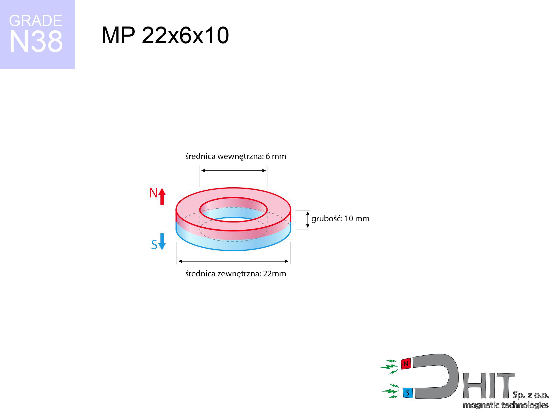
MP 22x6x10 / N38 - ring magnet
ring magnet
Catalog no 030394
GTIN/EAN: 5906301812319
Diameter
22 mm [±0,1 mm]
internal diameter Ø
6 mm [±0,1 mm]
Height
10 mm [±0,1 mm]
Weight
26.39 g
Magnetization Direction
↑ axial
Load capacity
13.65 kg / 133.89 N
Magnetic Induction
416.85 mT / 4168 Gs
Coating
[NiCuNi] Nickel
13.95 ZŁ with VAT / pcs + price for transport
11.34 ZŁ net + 23% VAT / pcs
bulk discounts:
Need more?Engineering report for this magnet
Full PDF analysis: pull and shear force, effect of distance, temperature and plate thickness, safety distances and the demagnetization curve.
Pick up the phone and ask
+48 22 499 98 98
if you prefer let us know through
request form
the contact section.
Weight as well as shape of neodymium magnets can be calculated on our
power calculator.
Same-day shipping for orders placed before 14:00.
Product card - MP 22x6x10 / N38 - ring magnet
Specification / characteristics - MP 22x6x10 / N38 - ring magnet
| properties | values |
|---|---|
| Cat. no. | 030394 |
| GTIN/EAN | 5906301812319 |
| Production/Distribution | Dhit sp. z o.o. |
| Country of origin | Poland / China / Germany |
| Customs code | 85059029 |
| Diameter | 22 mm [±0,1 mm] |
| internal diameter Ø | 6 mm [±0,1 mm] |
| Height | 10 mm [±0,1 mm] |
| Weight | 26.39 g |
| Magnetization Direction | ↑ axial |
| Load capacity ~ ? | 13.65 kg / 133.89 N |
| Magnetic Induction ~ ? | 416.85 mT / 4168 Gs |
| Coating | [NiCuNi] Nickel |
| Manufacturing Tolerance | ±0.1 mm |
Magnetic properties of material N38
| properties | values | units |
|---|---|---|
| remenance Br [min. - max.] ? | 12.2-12.6 | kGs |
| remenance Br [min. - max.] ? | 1220-1260 | mT |
| coercivity bHc ? | 10.8-11.5 | kOe |
| coercivity bHc ? | 860-915 | kA/m |
| actual internal force iHc | ≥ 12 | kOe |
| actual internal force iHc | ≥ 955 | kA/m |
| energy density [min. - max.] ? | 36-38 | BH max MGOe |
| energy density [min. - max.] ? | 287-303 | BH max KJ/m |
| max. temperature ? | ≤ 80 | °C |
Physical properties of sintered neodymium magnets Nd2Fe14B at 20°C
| properties | values | units |
|---|---|---|
| Vickers hardness | ≥550 | Hv |
| Density | ≥7.4 | g/cm3 |
| Curie Temperature TC | 312 - 380 | °C |
| Curie Temperature TF | 593 - 716 | °F |
| Specific resistance | 150 | μΩ⋅cm |
| Bending strength | 250 | MPa |
| Compressive strength | 1000~1100 | MPa |
| Thermal expansion parallel (∥) to orientation (M) | (3-4) x 10-6 | °C-1 |
| Thermal expansion perpendicular (⊥) to orientation (M) | -(1-3) x 10-6 | °C-1 |
| Young's modulus | 1.7 x 10⁴ | kg/mm² |
Engineering modeling of the product - data
These values constitute the outcome of a mathematical analysis. Results are based on models for the material Nd2Fe14B. Operational performance might slightly deviate from the simulation results. Please consider these data as a preliminary roadmap for designers.
Table 1: Static pull force (pull vs distance) - interaction chart
MP 22x6x10 / N38
| Distance (mm) | Induction (Gauss) / mT | Pull Force (kg/lbs/g/N) | Risk Status |
|---|---|---|---|
| 0 mm |
5864 Gs
586.4 mT
|
13.65 kg / 30.09 LBS
13650.0 g / 133.9 N
|
crushing |
| 1 mm |
5326 Gs
532.6 mT
|
11.26 kg / 24.83 LBS
11261.1 g / 110.5 N
|
crushing |
| 2 mm |
4795 Gs
479.5 mT
|
9.13 kg / 20.12 LBS
9127.3 g / 89.5 N
|
warning |
| 3 mm |
4288 Gs
428.8 mT
|
7.30 kg / 16.09 LBS
7299.8 g / 71.6 N
|
warning |
| 5 mm |
3381 Gs
338.1 mT
|
4.54 kg / 10.01 LBS
4539.0 g / 44.5 N
|
warning |
| 10 mm |
1830 Gs
183.0 mT
|
1.33 kg / 2.93 LBS
1329.4 g / 13.0 N
|
weak grip |
| 15 mm |
1039 Gs
103.9 mT
|
0.43 kg / 0.95 LBS
428.7 g / 4.2 N
|
weak grip |
| 20 mm |
635 Gs
63.5 mT
|
0.16 kg / 0.35 LBS
159.9 g / 1.6 N
|
weak grip |
| 30 mm |
285 Gs
28.5 mT
|
0.03 kg / 0.07 LBS
32.1 g / 0.3 N
|
weak grip |
| 50 mm |
90 Gs
9.0 mT
|
0.00 kg / 0.01 LBS
3.2 g / 0.0 N
|
weak grip |
Table 2: Sliding hold (wall)
MP 22x6x10 / N38
| Distance (mm) | Friction coefficient | Pull Force (kg/lbs/g/N) |
|---|---|---|
| 0 mm | Stal (~0.2) |
2.73 kg / 6.02 LBS
2730.0 g / 26.8 N
|
| 1 mm | Stal (~0.2) |
2.25 kg / 4.96 LBS
2252.0 g / 22.1 N
|
| 2 mm | Stal (~0.2) |
1.83 kg / 4.03 LBS
1826.0 g / 17.9 N
|
| 3 mm | Stal (~0.2) |
1.46 kg / 3.22 LBS
1460.0 g / 14.3 N
|
| 5 mm | Stal (~0.2) |
0.91 kg / 2.00 LBS
908.0 g / 8.9 N
|
| 10 mm | Stal (~0.2) |
0.27 kg / 0.59 LBS
266.0 g / 2.6 N
|
| 15 mm | Stal (~0.2) |
0.09 kg / 0.19 LBS
86.0 g / 0.8 N
|
| 20 mm | Stal (~0.2) |
0.03 kg / 0.07 LBS
32.0 g / 0.3 N
|
| 30 mm | Stal (~0.2) |
0.01 kg / 0.01 LBS
6.0 g / 0.1 N
|
| 50 mm | Stal (~0.2) |
0.00 kg / 0.00 LBS
0.0 g / 0.0 N
|
Table 3: Wall mounting (shearing) - behavior on slippery surfaces
MP 22x6x10 / N38
| Surface type | Friction coefficient / % Mocy | Max load (kg/lbs/g/N) |
|---|---|---|
| Raw steel |
µ = 0.3
30% Nominalnej Siły
|
4.10 kg / 9.03 LBS
4095.0 g / 40.2 N
|
| Painted steel (standard) |
µ = 0.2
20% Nominalnej Siły
|
2.73 kg / 6.02 LBS
2730.0 g / 26.8 N
|
| Oily/slippery steel |
µ = 0.1
10% Nominalnej Siły
|
1.37 kg / 3.01 LBS
1365.0 g / 13.4 N
|
| Magnet with anti-slip rubber |
µ = 0.5
50% Nominalnej Siły
|
6.83 kg / 15.05 LBS
6825.0 g / 67.0 N
|
Table 4: Material efficiency (substrate influence) - sheet metal selection
MP 22x6x10 / N38
| Steel thickness (mm) | % power | Real pull force (kg/lbs/g/N) |
|---|---|---|
| 0.5 mm |
|
0.68 kg / 1.50 LBS
682.5 g / 6.7 N
|
| 1 mm |
|
1.71 kg / 3.76 LBS
1706.3 g / 16.7 N
|
| 2 mm |
|
3.41 kg / 7.52 LBS
3412.5 g / 33.5 N
|
| 3 mm |
|
5.12 kg / 11.28 LBS
5118.8 g / 50.2 N
|
| 5 mm |
|
8.53 kg / 18.81 LBS
8531.3 g / 83.7 N
|
| 10 mm |
|
13.65 kg / 30.09 LBS
13650.0 g / 133.9 N
|
| 11 mm |
|
13.65 kg / 30.09 LBS
13650.0 g / 133.9 N
|
| 12 mm |
|
13.65 kg / 30.09 LBS
13650.0 g / 133.9 N
|
Table 5: Thermal resistance (material behavior) - resistance threshold
MP 22x6x10 / N38
| Ambient temp. (°C) | Power loss | Remaining pull (kg/lbs/g/N) | Status |
|---|---|---|---|
| 20 °C | 0.0% |
13.65 kg / 30.09 LBS
13650.0 g / 133.9 N
|
OK |
| 40 °C | -2.2% |
13.35 kg / 29.43 LBS
13349.7 g / 131.0 N
|
OK |
| 60 °C | -4.4% |
13.05 kg / 28.77 LBS
13049.4 g / 128.0 N
|
OK |
| 80 °C | -6.6% |
12.75 kg / 28.11 LBS
12749.1 g / 125.1 N
|
|
| 100 °C | -28.8% |
9.72 kg / 21.43 LBS
9718.8 g / 95.3 N
|
Table 6: Magnet-Magnet interaction (attraction) - field collision
MP 22x6x10 / N38
| Gap (mm) | Attraction (kg/lbs) (N-S) | Shear Strength (kg/lbs/g/N) | Repulsion (kg/lbs) (N-N) |
|---|---|---|---|
| 0 mm |
54.34 kg / 119.79 LBS
6 106 Gs
|
8.15 kg / 17.97 LBS
8151 g / 80.0 N
|
N/A |
| 1 mm |
49.50 kg / 109.14 LBS
11 193 Gs
|
7.43 kg / 16.37 LBS
7426 g / 72.8 N
|
44.55 kg / 98.22 LBS
~0 Gs
|
| 2 mm |
44.83 kg / 98.83 LBS
10 652 Gs
|
6.72 kg / 14.82 LBS
6724 g / 66.0 N
|
40.34 kg / 88.94 LBS
~0 Gs
|
| 3 mm |
40.43 kg / 89.14 LBS
10 116 Gs
|
6.06 kg / 13.37 LBS
6065 g / 59.5 N
|
36.39 kg / 80.22 LBS
~0 Gs
|
| 5 mm |
32.54 kg / 71.74 LBS
9 075 Gs
|
4.88 kg / 10.76 LBS
4881 g / 47.9 N
|
29.29 kg / 64.57 LBS
~0 Gs
|
| 10 mm |
18.07 kg / 39.83 LBS
6 762 Gs
|
2.71 kg / 5.98 LBS
2710 g / 26.6 N
|
16.26 kg / 35.85 LBS
~0 Gs
|
| 20 mm |
5.29 kg / 11.67 LBS
3 660 Gs
|
0.79 kg / 1.75 LBS
794 g / 7.8 N
|
4.76 kg / 10.50 LBS
~0 Gs
|
| 50 mm |
0.27 kg / 0.60 LBS
828 Gs
|
0.04 kg / 0.09 LBS
41 g / 0.4 N
|
0.24 kg / 0.54 LBS
~0 Gs
|
| 60 mm |
0.13 kg / 0.28 LBS
569 Gs
|
0.02 kg / 0.04 LBS
19 g / 0.2 N
|
0.12 kg / 0.25 LBS
~0 Gs
|
| 70 mm |
0.07 kg / 0.15 LBS
408 Gs
|
0.01 kg / 0.02 LBS
10 g / 0.1 N
|
0.06 kg / 0.13 LBS
~0 Gs
|
| 80 mm |
0.04 kg / 0.08 LBS
303 Gs
|
0.01 kg / 0.01 LBS
5 g / 0.1 N
|
0.03 kg / 0.07 LBS
~0 Gs
|
| 90 mm |
0.02 kg / 0.05 LBS
231 Gs
|
0.00 kg / 0.01 LBS
3 g / 0.0 N
|
0.02 kg / 0.04 LBS
~0 Gs
|
| 100 mm |
0.01 kg / 0.03 LBS
180 Gs
|
0.00 kg / 0.00 LBS
2 g / 0.0 N
|
0.01 kg / 0.03 LBS
~0 Gs
|
Table 7: Safety (HSE) (implants) - warnings
MP 22x6x10 / N38
| Object / Device | Limit (Gauss) / mT | Safe distance |
|---|---|---|
| Pacemaker | 5 Gs (0.5 mT) | 15.5 cm |
| Hearing aid | 10 Gs (1.0 mT) | 12.0 cm |
| Timepiece | 20 Gs (2.0 mT) | 9.5 cm |
| Phone / Smartphone | 40 Gs (4.0 mT) | 7.0 cm |
| Car key | 50 Gs (5.0 mT) | 6.5 cm |
| Payment card | 400 Gs (40.0 mT) | 3.0 cm |
| HDD hard drive | 600 Gs (60.0 mT) | 2.5 cm |
Table 8: Collisions (cracking risk) - collision effects
MP 22x6x10 / N38
| Start from (mm) | Speed (km/h) | Energy (J) | Predicted outcome |
|---|---|---|---|
| 10 mm |
24.29 km/h
(6.75 m/s)
|
0.60 J | |
| 30 mm |
39.79 km/h
(11.05 m/s)
|
1.61 J | |
| 50 mm |
51.30 km/h
(14.25 m/s)
|
2.68 J | |
| 100 mm |
72.53 km/h
(20.15 m/s)
|
5.36 J |
Table 9: Anti-corrosion coating durability
MP 22x6x10 / N38
| Technical parameter | Value / Description |
|---|---|
| Coating type | [NiCuNi] Nickel |
| Layer structure | Nickel - Copper - Nickel |
| Layer thickness | 10-20 µm |
| Salt spray test (SST) ? | 24 h |
| Recommended environment | Indoors only (dry) |
Table 10: Electrical data (Flux)
MP 22x6x10 / N38
| Parameter | Value | SI Unit / Description |
|---|---|---|
| Magnetic Flux | 16 465 Mx | 164.7 µWb |
| Pc Coefficient | 1.13 | High (Stable) |
Table 11: Physics of underwater searching
MP 22x6x10 / N38
| Environment | Effective steel pull | Effect |
|---|---|---|
| Air (land) | 13.65 kg | Standard |
| Water (riverbed) |
15.63 kg
(+1.98 kg buoyancy gain)
|
+14.5% |
1. Vertical hold
*Caution: On a vertical surface, the magnet holds just approx. 20-30% of its max power.
2. Steel saturation
*Thin steel (e.g. 0.5mm PC case) drastically reduces the holding force.
3. Thermal stability
*For N38 grade, the critical limit is 80°C.
4. Demagnetization curve and operating point (B-H)
chart generated for the permeance coefficient Pc (Permeance Coefficient) = 1.13
This simulation demonstrates the magnetic stability of the selected magnet under specific geometric conditions. The solid red line represents the demagnetization curve (material potential), while the dashed blue line is the load line based on the magnet's geometry. The Pc (Permeance Coefficient), also known as the load line slope, is a dimensionless value that describes the relationship between the magnet's shape and its magnetic stability. The intersection of these two lines (the black dot) is the operating point — it determines the actual magnetic flux density generated by the magnet in this specific configuration. A higher Pc value means the magnet is more 'slender' (tall relative to its area), resulting in a higher operating point and better resistance to irreversible demagnetization caused by external fields or temperature. A value of 0.42 is relatively low (typical for flat magnets), meaning the operating point is closer to the 'knee' of the curve — caution is advised when operating at temperatures near the maximum limit to avoid strength loss.
Chemical composition
| iron (Fe) | 64% – 68% |
| neodymium (Nd) | 29% – 32% |
| boron (B) | 1.1% – 1.2% |
| dysprosium (Dy) | 0.5% – 2.0% |
| coating (Ni-Cu-Ni) | < 0.05% |
Environmental data
| recyclability (EoL) | 100% |
| recycled raw materials | ~10% (pre-cons) |
| carbon footprint | low / zredukowany |
| waste code (EWC) | 16 02 16 |
See also offers
![SM 25x300 [2xM8] / N42 - magnetic separator](https://cdn3.dhit.pl/graphics/products/sm-25x300-2xm8-kud.jpg "SM 25x300 [2xM8] / N42 - magnetic separator")


![UMGZ 36x18x8 [M6] GZ / N38 - magnetic holder external thread](https://cdn3.dhit.pl/graphics/products/um-36x18x8-m8-gz-xiv.jpg "UMGZ 36x18x8 [M6] GZ / N38 - magnetic holder external thread")
Advantages and disadvantages of neodymium magnets.
Strengths
- They have stable power, and over nearly 10 years their performance decreases symbolically – ~1% (according to theory),
- They show high resistance to demagnetization induced by presence of other magnetic fields,
- Thanks to the glossy finish, the coating of nickel, gold-plated, or silver gives an clean appearance,
- Magnetic induction on the top side of the magnet is very high,
- Neodymium magnets are characterized by very high magnetic induction on the magnet surface and can function (depending on the shape) even at a temperature of 230°C or more...
- Possibility of exact machining as well as modifying to specific requirements,
- Versatile presence in modern industrial fields – they are used in computer drives, motor assemblies, precision medical tools, also complex engineering applications.
- Relatively small size with high pulling force – neodymium magnets offer high power in compact dimensions, which allows their use in small systems
Cons
- At very strong impacts they can break, therefore we advise placing them in special holders. A metal housing provides additional protection against damage, as well as increases the magnet's durability.
- Neodymium magnets demagnetize when exposed to high temperatures. After reaching 80°C, many of them experience permanent drop of strength (a factor is the shape as well as dimensions of the magnet). We offer magnets specially adapted to work at temperatures up to 230°C marked [AH], which are very resistant to heat
- Due to the susceptibility of magnets to corrosion in a humid environment, we recommend using waterproof magnets made of rubber, plastic or other material immune to moisture, in case of application outdoors
- We suggest cover - magnetic holder, due to difficulties in creating nuts inside the magnet and complicated forms.
- Possible danger resulting from small fragments of magnets are risky, when accidentally swallowed, which gains importance in the context of child health protection. Additionally, tiny parts of these devices can complicate diagnosis medical in case of swallowing.
- Due to expensive raw materials, their price is relatively high,
Pull force analysis
Maximum lifting force for a neodymium magnet – what contributes to it?
- using a base made of high-permeability steel, functioning as a circuit closing element
- with a thickness of at least 10 mm
- with an ideally smooth contact surface
- without the slightest insulating layer between the magnet and steel
- for force applied at a right angle (in the magnet axis)
- at ambient temperature room level
What influences lifting capacity in practice
- Air gap (betwixt the magnet and the plate), because even a very small distance (e.g. 0.5 mm) leads to a decrease in lifting capacity by up to 50% (this also applies to varnish, corrosion or dirt).
- Loading method – declared lifting capacity refers to pulling vertically. When attempting to slide, the magnet holds much less (often approx. 20-30% of nominal force).
- Steel thickness – insufficiently thick steel causes magnetic saturation, causing part of the flux to be lost to the other side.
- Material composition – not every steel reacts the same. Alloy additives worsen the interaction with the magnet.
- Surface finish – ideal contact is obtained only on polished steel. Any scratches and bumps reduce the real contact area, weakening the magnet.
- Temperature influence – high temperature reduces pulling force. Exceeding the limit temperature can permanently demagnetize the magnet.
Lifting capacity testing was performed on a smooth plate of suitable thickness, under a perpendicular pulling force, whereas under attempts to slide the magnet the lifting capacity is smaller. Additionally, even a small distance between the magnet’s surface and the plate reduces the holding force.
Precautions when working with NdFeB magnets
Skin irritation risks
A percentage of the population have a sensitization to Ni, which is the typical protective layer for neodymium magnets. Prolonged contact can result in an allergic reaction. We recommend use protective gloves.
Fire warning
Drilling and cutting of neodymium magnets carries a risk of fire hazard. Neodymium dust reacts violently with oxygen and is difficult to extinguish.
Caution required
Handle magnets with awareness. Their huge power can shock even experienced users. Be vigilant and respect their power.
Implant safety
People with a ICD should keep an safe separation from magnets. The magnetic field can disrupt the functioning of the life-saving device.
Demagnetization risk
Watch the temperature. Heating the magnet above 80 degrees Celsius will ruin its properties and strength.
Swallowing risk
Adult use only. Small elements can be swallowed, causing serious injuries. Store away from children and animals.
Precision electronics
Navigation devices and smartphones are extremely susceptible to magnetism. Close proximity with a powerful NdFeB magnet can decalibrate the sensors in your phone.
Finger safety
Large magnets can crush fingers in a fraction of a second. Never put your hand betwixt two strong magnets.
Electronic hazard
Equipment safety: Strong magnets can ruin data carriers and delicate electronics (heart implants, medical aids, timepieces).
Risk of cracking
Protect your eyes. Magnets can fracture upon violent connection, launching sharp fragments into the air. We recommend safety glasses.
Tabela kosztu i czasu dostawy
Płatność przed wysyłką:

GLS kurier
Przesyłka będzie u Ciebie za 2-3 dni
14.99 ZŁ

InPost Paczkomaty 24/7
Przesyłka będzie u Ciebie za 1-2 dni
12.30 ZŁ
Płatność przy odbiorze (pobranie):
GLS kurier
Przesyłka będzie u Ciebie za 1-2 dni
23.00 ZŁ
Rate the product
Your rating