
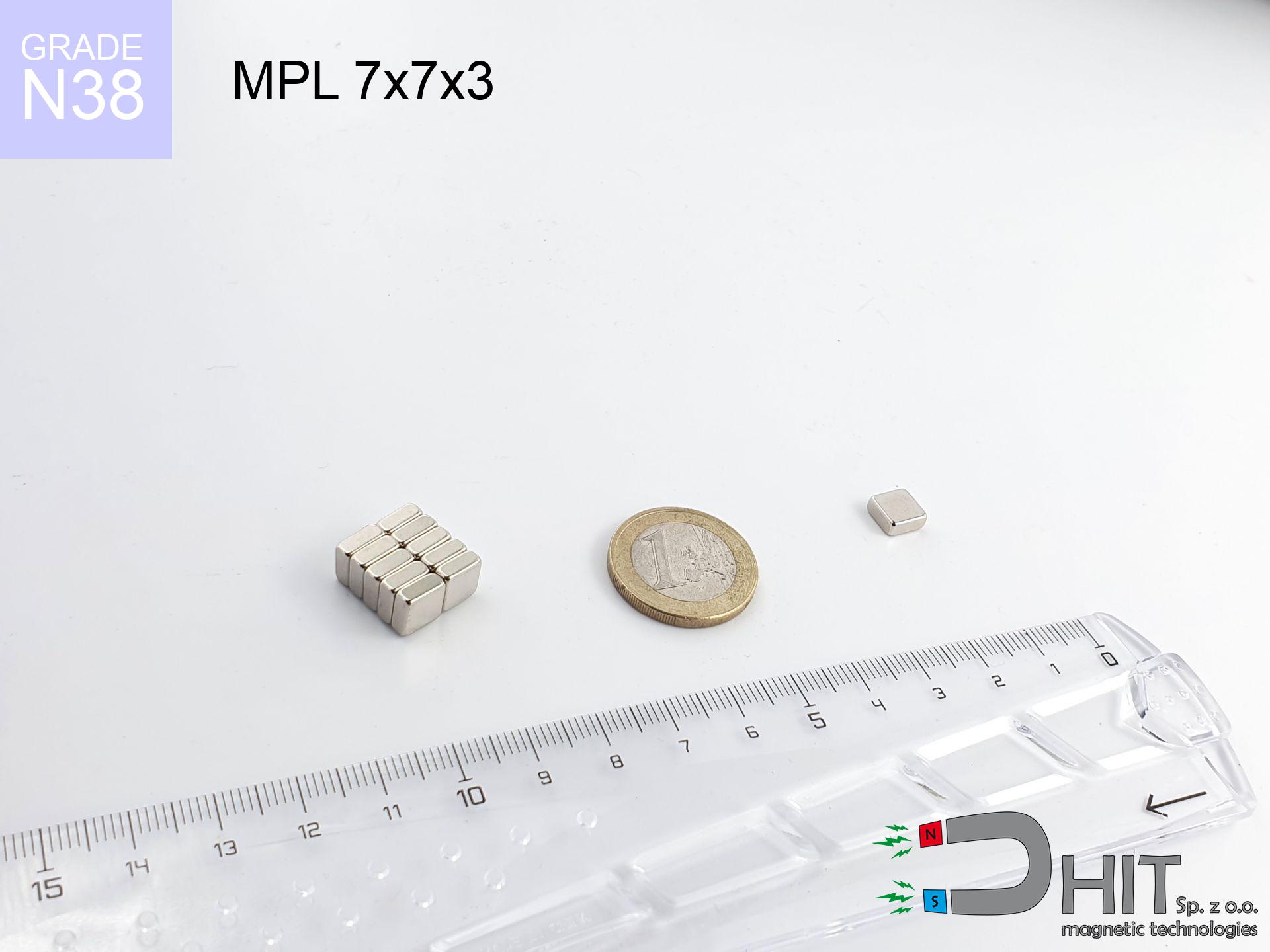
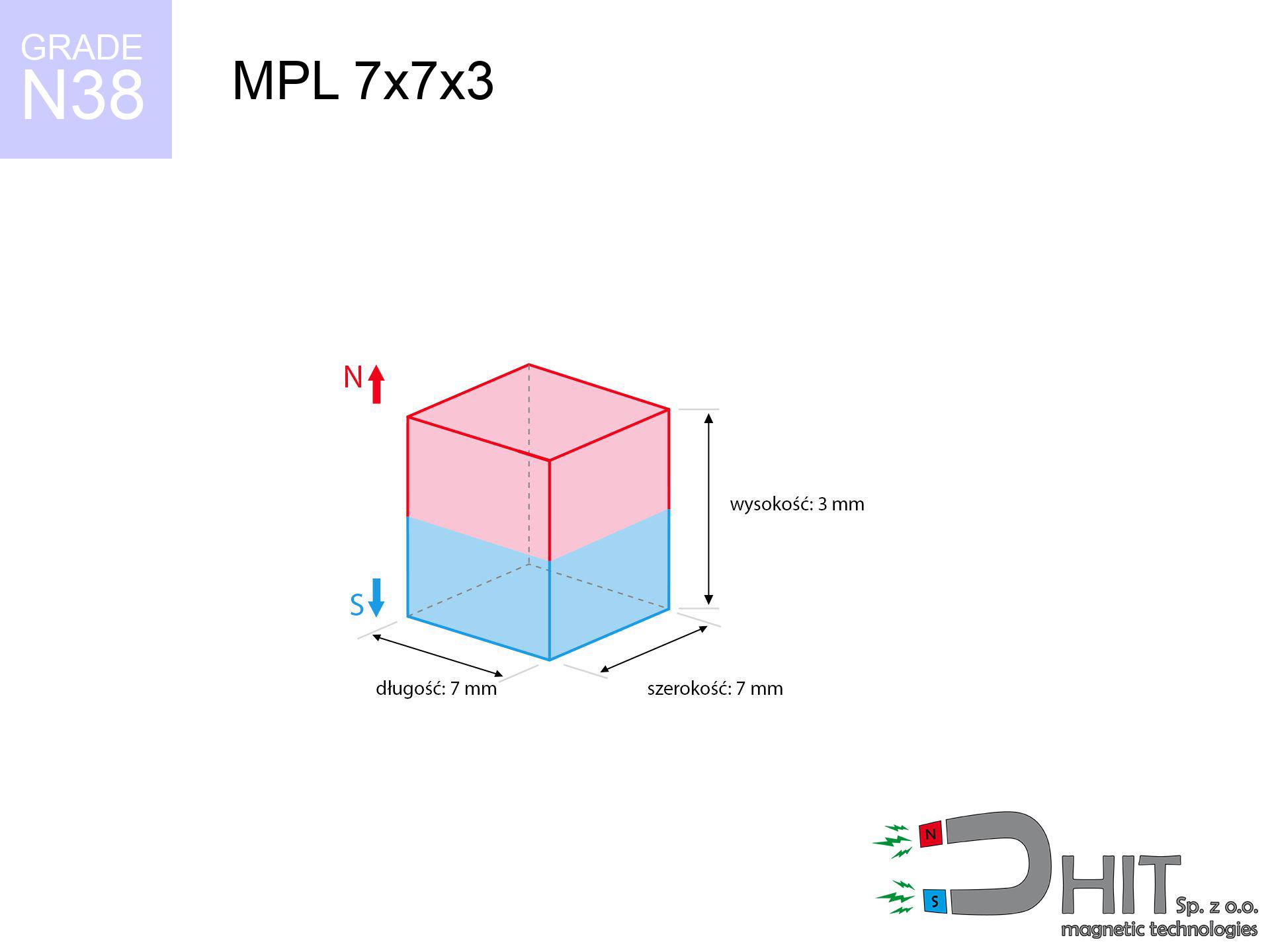
MPL 7x7x3 / N38 - lamellar magnet
lamellar magnet
Catalog no 020176
GTIN/EAN: 5906301811824
length
7 mm [±0,1 mm]
Width
7 mm [±0,1 mm]
Height
3 mm [±0,1 mm]
Weight
1.1 g
Magnetization Direction
↑ axial
Load capacity
1.60 kg / 15.70 N
Magnetic Induction
376.99 mT / 3770 Gs
Coating
[NiCuNi] Nickel
0.541 ZŁ with VAT / pcs + price for transport
0.440 ZŁ net + 23% VAT / pcs
bulk discounts:
Need more?
Contact us by phone
+48 888 99 98 98
or let us know using
our online form
our website.
Lifting power as well as shape of magnets can be analyzed using our
magnetic mass calculator.
Orders placed before 14:00 will be shipped the same business day.
Product card - MPL 7x7x3 / N38 - lamellar magnet
Specification / characteristics - MPL 7x7x3 / N38 - lamellar magnet
| properties | values |
|---|---|
| Cat. no. | 020176 |
| GTIN/EAN | 5906301811824 |
| Production/Distribution | Dhit sp. z o.o. |
| Country of origin | Poland / China / Germany |
| Customs code | 85059029 |
| length | 7 mm [±0,1 mm] |
| Width | 7 mm [±0,1 mm] |
| Height | 3 mm [±0,1 mm] |
| Weight | 1.1 g |
| Magnetization Direction | ↑ axial |
| Load capacity ~ ? | 1.60 kg / 15.70 N |
| Magnetic Induction ~ ? | 376.99 mT / 3770 Gs |
| Coating | [NiCuNi] Nickel |
| Manufacturing Tolerance | ±0.1 mm |
Magnetic properties of material N38
| properties | values | units |
|---|---|---|
| remenance Br [min. - max.] ? | 12.2-12.6 | kGs |
| remenance Br [min. - max.] ? | 1220-1260 | mT |
| coercivity bHc ? | 10.8-11.5 | kOe |
| coercivity bHc ? | 860-915 | kA/m |
| actual internal force iHc | ≥ 12 | kOe |
| actual internal force iHc | ≥ 955 | kA/m |
| energy density [min. - max.] ? | 36-38 | BH max MGOe |
| energy density [min. - max.] ? | 287-303 | BH max KJ/m |
| max. temperature ? | ≤ 80 | °C |
Physical properties of sintered neodymium magnets Nd2Fe14B at 20°C
| properties | values | units |
|---|---|---|
| Vickers hardness | ≥550 | Hv |
| Density | ≥7.4 | g/cm3 |
| Curie Temperature TC | 312 - 380 | °C |
| Curie Temperature TF | 593 - 716 | °F |
| Specific resistance | 150 | μΩ⋅cm |
| Bending strength | 250 | MPa |
| Compressive strength | 1000~1100 | MPa |
| Thermal expansion parallel (∥) to orientation (M) | (3-4) x 10-6 | °C-1 |
| Thermal expansion perpendicular (⊥) to orientation (M) | -(1-3) x 10-6 | °C-1 |
| Young's modulus | 1.7 x 10⁴ | kg/mm² |
Engineering simulation of the product - data
The following values are the result of a mathematical analysis. Values rely on algorithms for the class Nd2Fe14B. Actual parameters may differ from theoretical values. Please consider these data as a supplementary guide during assembly planning.
Table 1: Static pull force (force vs distance) - characteristics
MPL 7x7x3 / N38
| Distance (mm) | Induction (Gauss) / mT | Pull Force (kg/lbs/g/N) | Risk Status |
|---|---|---|---|
| 0 mm |
3767 Gs
376.7 mT
|
1.60 kg / 3.53 pounds
1600.0 g / 15.7 N
|
low risk |
| 1 mm |
2886 Gs
288.6 mT
|
0.94 kg / 2.07 pounds
939.5 g / 9.2 N
|
low risk |
| 2 mm |
2048 Gs
204.8 mT
|
0.47 kg / 1.04 pounds
472.8 g / 4.6 N
|
low risk |
| 3 mm |
1412 Gs
141.2 mT
|
0.22 kg / 0.50 pounds
224.8 g / 2.2 N
|
low risk |
| 5 mm |
686 Gs
68.6 mT
|
0.05 kg / 0.12 pounds
53.0 g / 0.5 N
|
low risk |
| 10 mm |
165 Gs
16.5 mT
|
0.00 kg / 0.01 pounds
3.1 g / 0.0 N
|
low risk |
| 15 mm |
60 Gs
6.0 mT
|
0.00 kg / 0.00 pounds
0.4 g / 0.0 N
|
low risk |
| 20 mm |
28 Gs
2.8 mT
|
0.00 kg / 0.00 pounds
0.1 g / 0.0 N
|
low risk |
| 30 mm |
9 Gs
0.9 mT
|
0.00 kg / 0.00 pounds
0.0 g / 0.0 N
|
low risk |
| 50 mm |
2 Gs
0.2 mT
|
0.00 kg / 0.00 pounds
0.0 g / 0.0 N
|
low risk |
Table 2: Slippage load (vertical surface)
MPL 7x7x3 / N38
| Distance (mm) | Friction coefficient | Pull Force (kg/lbs/g/N) |
|---|---|---|
| 0 mm | Stal (~0.2) |
0.32 kg / 0.71 pounds
320.0 g / 3.1 N
|
| 1 mm | Stal (~0.2) |
0.19 kg / 0.41 pounds
188.0 g / 1.8 N
|
| 2 mm | Stal (~0.2) |
0.09 kg / 0.21 pounds
94.0 g / 0.9 N
|
| 3 mm | Stal (~0.2) |
0.04 kg / 0.10 pounds
44.0 g / 0.4 N
|
| 5 mm | Stal (~0.2) |
0.01 kg / 0.02 pounds
10.0 g / 0.1 N
|
| 10 mm | Stal (~0.2) |
0.00 kg / 0.00 pounds
0.0 g / 0.0 N
|
| 15 mm | Stal (~0.2) |
0.00 kg / 0.00 pounds
0.0 g / 0.0 N
|
| 20 mm | Stal (~0.2) |
0.00 kg / 0.00 pounds
0.0 g / 0.0 N
|
| 30 mm | Stal (~0.2) |
0.00 kg / 0.00 pounds
0.0 g / 0.0 N
|
| 50 mm | Stal (~0.2) |
0.00 kg / 0.00 pounds
0.0 g / 0.0 N
|
Table 3: Wall mounting (sliding) - behavior on slippery surfaces
MPL 7x7x3 / N38
| Surface type | Friction coefficient / % Mocy | Max load (kg/lbs/g/N) |
|---|---|---|
| Raw steel |
µ = 0.3
30% Nominalnej Siły
|
0.48 kg / 1.06 pounds
480.0 g / 4.7 N
|
| Painted steel (standard) |
µ = 0.2
20% Nominalnej Siły
|
0.32 kg / 0.71 pounds
320.0 g / 3.1 N
|
| Oily/slippery steel |
µ = 0.1
10% Nominalnej Siły
|
0.16 kg / 0.35 pounds
160.0 g / 1.6 N
|
| Magnet with anti-slip rubber |
µ = 0.5
50% Nominalnej Siły
|
0.80 kg / 1.76 pounds
800.0 g / 7.8 N
|
Table 4: Steel thickness (saturation) - sheet metal selection
MPL 7x7x3 / N38
| Steel thickness (mm) | % power | Real pull force (kg/lbs/g/N) |
|---|---|---|
| 0.5 mm |
|
0.16 kg / 0.35 pounds
160.0 g / 1.6 N
|
| 1 mm |
|
0.40 kg / 0.88 pounds
400.0 g / 3.9 N
|
| 2 mm |
|
0.80 kg / 1.76 pounds
800.0 g / 7.8 N
|
| 3 mm |
|
1.20 kg / 2.65 pounds
1200.0 g / 11.8 N
|
| 5 mm |
|
1.60 kg / 3.53 pounds
1600.0 g / 15.7 N
|
| 10 mm |
|
1.60 kg / 3.53 pounds
1600.0 g / 15.7 N
|
| 11 mm |
|
1.60 kg / 3.53 pounds
1600.0 g / 15.7 N
|
| 12 mm |
|
1.60 kg / 3.53 pounds
1600.0 g / 15.7 N
|
Table 5: Thermal resistance (material behavior) - power drop
MPL 7x7x3 / N38
| Ambient temp. (°C) | Power loss | Remaining pull (kg/lbs/g/N) | Status |
|---|---|---|---|
| 20 °C | 0.0% |
1.60 kg / 3.53 pounds
1600.0 g / 15.7 N
|
OK |
| 40 °C | -2.2% |
1.56 kg / 3.45 pounds
1564.8 g / 15.4 N
|
OK |
| 60 °C | -4.4% |
1.53 kg / 3.37 pounds
1529.6 g / 15.0 N
|
|
| 80 °C | -6.6% |
1.49 kg / 3.29 pounds
1494.4 g / 14.7 N
|
|
| 100 °C | -28.8% |
1.14 kg / 2.51 pounds
1139.2 g / 11.2 N
|
Table 6: Magnet-Magnet interaction (attraction) - field range
MPL 7x7x3 / N38
| Gap (mm) | Attraction (kg/lbs) (N-S) | Shear Strength (kg/lbs/g/N) | Repulsion (kg/lbs) (N-N) |
|---|---|---|---|
| 0 mm |
4.29 kg / 9.45 pounds
5 173 Gs
|
0.64 kg / 1.42 pounds
643 g / 6.3 N
|
N/A |
| 1 mm |
3.38 kg / 7.44 pounds
6 685 Gs
|
0.51 kg / 1.12 pounds
506 g / 5.0 N
|
3.04 kg / 6.70 pounds
~0 Gs
|
| 2 mm |
2.52 kg / 5.55 pounds
5 773 Gs
|
0.38 kg / 0.83 pounds
378 g / 3.7 N
|
2.27 kg / 4.99 pounds
~0 Gs
|
| 3 mm |
1.81 kg / 3.99 pounds
4 893 Gs
|
0.27 kg / 0.60 pounds
271 g / 2.7 N
|
1.63 kg / 3.59 pounds
~0 Gs
|
| 5 mm |
0.88 kg / 1.93 pounds
3 405 Gs
|
0.13 kg / 0.29 pounds
131 g / 1.3 N
|
0.79 kg / 1.74 pounds
~0 Gs
|
| 10 mm |
0.14 kg / 0.31 pounds
1 372 Gs
|
0.02 kg / 0.05 pounds
21 g / 0.2 N
|
0.13 kg / 0.28 pounds
~0 Gs
|
| 20 mm |
0.01 kg / 0.02 pounds
329 Gs
|
0.00 kg / 0.00 pounds
1 g / 0.0 N
|
0.00 kg / 0.00 pounds
~0 Gs
|
| 50 mm |
0.00 kg / 0.00 pounds
30 Gs
|
0.00 kg / 0.00 pounds
0 g / 0.0 N
|
0.00 kg / 0.00 pounds
~0 Gs
|
| 60 mm |
0.00 kg / 0.00 pounds
18 Gs
|
0.00 kg / 0.00 pounds
0 g / 0.0 N
|
0.00 kg / 0.00 pounds
~0 Gs
|
| 70 mm |
0.00 kg / 0.00 pounds
12 Gs
|
0.00 kg / 0.00 pounds
0 g / 0.0 N
|
0.00 kg / 0.00 pounds
~0 Gs
|
| 80 mm |
0.00 kg / 0.00 pounds
8 Gs
|
0.00 kg / 0.00 pounds
0 g / 0.0 N
|
0.00 kg / 0.00 pounds
~0 Gs
|
| 90 mm |
0.00 kg / 0.00 pounds
6 Gs
|
0.00 kg / 0.00 pounds
0 g / 0.0 N
|
0.00 kg / 0.00 pounds
~0 Gs
|
| 100 mm |
0.00 kg / 0.00 pounds
4 Gs
|
0.00 kg / 0.00 pounds
0 g / 0.0 N
|
0.00 kg / 0.00 pounds
~0 Gs
|
Table 7: Protective zones (electronics) - warnings
MPL 7x7x3 / N38
| Object / Device | Limit (Gauss) / mT | Safe distance |
|---|---|---|
| Pacemaker | 5 Gs (0.5 mT) | 4.0 cm |
| Hearing aid | 10 Gs (1.0 mT) | 3.0 cm |
| Mechanical watch | 20 Gs (2.0 mT) | 2.5 cm |
| Phone / Smartphone | 40 Gs (4.0 mT) | 2.0 cm |
| Remote | 50 Gs (5.0 mT) | 2.0 cm |
| Payment card | 400 Gs (40.0 mT) | 1.0 cm |
| HDD hard drive | 600 Gs (60.0 mT) | 1.0 cm |
Table 8: Impact energy (cracking risk) - collision effects
MPL 7x7x3 / N38
| Start from (mm) | Speed (km/h) | Energy (J) | Predicted outcome |
|---|---|---|---|
| 10 mm |
38.51 km/h
(10.70 m/s)
|
0.06 J | |
| 30 mm |
66.62 km/h
(18.51 m/s)
|
0.19 J | |
| 50 mm |
86.01 km/h
(23.89 m/s)
|
0.31 J | |
| 100 mm |
121.63 km/h
(33.79 m/s)
|
0.63 J |
Table 9: Corrosion resistance
MPL 7x7x3 / N38
| Technical parameter | Value / Description |
|---|---|
| Coating type | [NiCuNi] Nickel |
| Layer structure | Nickel - Copper - Nickel |
| Layer thickness | 10-20 µm |
| Salt spray test (SST) ? | 24 h |
| Recommended environment | Indoors only (dry) |
Table 10: Electrical data (Pc)
MPL 7x7x3 / N38
| Parameter | Value | SI Unit / Description |
|---|---|---|
| Magnetic Flux | 1 909 Mx | 19.1 µWb |
| Pc Coefficient | 0.48 | Low (Flat) |
Table 11: Hydrostatics and buoyancy
MPL 7x7x3 / N38
| Environment | Effective steel pull | Effect |
|---|---|---|
| Air (land) | 1.60 kg | Standard |
| Water (riverbed) |
1.83 kg
(+0.23 kg buoyancy gain)
|
+14.5% |
1. Wall mount (shear)
*Warning: On a vertical surface, the magnet holds only approx. 20-30% of its nominal pull.
2. Plate thickness effect
*Thin metal sheet (e.g. computer case) significantly reduces the holding force.
3. Power loss vs temp
*For N38 material, the safety limit is 80°C.
4. Demagnetization curve and operating point (B-H)
chart generated for the permeance coefficient Pc (Permeance Coefficient) = 0.48
This simulation demonstrates the magnetic stability of the selected magnet under specific geometric conditions. The solid red line represents the demagnetization curve (material potential), while the dashed blue line is the load line based on the magnet's geometry. The Pc (Permeance Coefficient), also known as the load line slope, is a dimensionless value that describes the relationship between the magnet's shape and its magnetic stability. The intersection of these two lines (the black dot) is the operating point — it determines the actual magnetic flux density generated by the magnet in this specific configuration. A higher Pc value means the magnet is more 'slender' (tall relative to its area), resulting in a higher operating point and better resistance to irreversible demagnetization caused by external fields or temperature. A value of 0.42 is relatively low (typical for flat magnets), meaning the operating point is closer to the 'knee' of the curve — caution is advised when operating at temperatures near the maximum limit to avoid strength loss.
Material specification
| iron (Fe) | 64% – 68% |
| neodymium (Nd) | 29% – 32% |
| boron (B) | 1.1% – 1.2% |
| dysprosium (Dy) | 0.5% – 2.0% |
| coating (Ni-Cu-Ni) | < 0.05% |
Sustainability
| recyclability (EoL) | 100% |
| recycled raw materials | ~10% (pre-cons) |
| carbon footprint | low / zredukowany |
| waste code (EWC) | 16 02 16 |
See more proposals
![SM 32x375 [2xM8] / N42 - magnetic separator](https://cdn3.dhit.pl/graphics/products/sm-32x375-2xm8-nif.jpg "SM 32x375 [2xM8] / N42 - magnetic separator")


Strengths and weaknesses of Nd2Fe14B magnets.
Benefits
- They retain magnetic properties for nearly 10 years – the loss is just ~1% (in theory),
- Neodymium magnets are characterized by extremely resistant to demagnetization caused by external magnetic fields,
- By applying a lustrous coating of gold, the element presents an nice look,
- Magnets possess huge magnetic induction on the working surface,
- Made from properly selected components, these magnets show impressive resistance to high heat, enabling them to function (depending on their form) at temperatures up to 230°C and above...
- Thanks to versatility in designing and the ability to modify to unusual requirements,
- Fundamental importance in electronics industry – they serve a role in mass storage devices, electric drive systems, medical devices, and complex engineering applications.
- Compactness – despite small sizes they generate large force, making them ideal for precision applications
Limitations
- To avoid cracks under impact, we recommend using special steel housings. Such a solution protects the magnet and simultaneously improves its durability.
- Neodymium magnets decrease their force under the influence of heating. As soon as 80°C is exceeded, many of them start losing their power. Therefore, we recommend our special magnets marked [AH], which maintain durability even at temperatures up to 230°C
- When exposed to humidity, magnets start to rust. To use them in conditions outside, it is recommended to use protective magnets, such as magnets in rubber or plastics, which prevent oxidation and corrosion.
- Limited possibility of making nuts in the magnet and complex shapes - preferred is cover - mounting mechanism.
- Potential hazard to health – tiny shards of magnets are risky, when accidentally swallowed, which is particularly important in the aspect of protecting the youngest. It is also worth noting that small elements of these devices can be problematic in diagnostics medical in case of swallowing.
- Due to expensive raw materials, their price exceeds standard values,
Lifting parameters
Detachment force of the magnet in optimal conditions – what it depends on?
- on a plate made of mild steel, effectively closing the magnetic field
- whose transverse dimension is min. 10 mm
- with a plane perfectly flat
- without any air gap between the magnet and steel
- for force applied at a right angle (pull-off, not shear)
- in stable room temperature
Lifting capacity in real conditions – factors
- Distance – existence of foreign body (rust, tape, gap) interrupts the magnetic circuit, which lowers power rapidly (even by 50% at 0.5 mm).
- Force direction – declared lifting capacity refers to detachment vertically. When applying parallel force, the magnet exhibits much less (typically approx. 20-30% of nominal force).
- Steel thickness – insufficiently thick steel causes magnetic saturation, causing part of the power to be lost to the other side.
- Metal type – different alloys reacts the same. Alloy additives weaken the attraction effect.
- Surface finish – full contact is obtained only on polished steel. Any scratches and bumps create air cushions, reducing force.
- Temperature influence – hot environment weakens pulling force. Too high temperature can permanently demagnetize the magnet.
Holding force was checked on the plate surface of 20 mm thickness, when the force acted perpendicularly, whereas under attempts to slide the magnet the load capacity is reduced by as much as fivefold. Additionally, even a small distance between the magnet and the plate lowers the holding force.
Warnings
Heat warning
Watch the temperature. Exposing the magnet above 80 degrees Celsius will ruin its magnetic structure and strength.
Serious injuries
Protect your hands. Two powerful magnets will join immediately with a force of massive weight, crushing everything in their path. Be careful!
Do not give to children
Always store magnets away from children. Risk of swallowing is high, and the effects of magnets connecting inside the body are very dangerous.
Electronic hazard
Data protection: Strong magnets can ruin data carriers and sensitive devices (heart implants, medical aids, mechanical watches).
Do not underestimate power
Exercise caution. Rare earth magnets act from a long distance and connect with huge force, often faster than you can move away.
Combustion hazard
Machining of neodymium magnets carries a risk of fire risk. Neodymium dust reacts violently with oxygen and is difficult to extinguish.
Magnet fragility
Protect your eyes. Magnets can fracture upon violent connection, launching sharp fragments into the air. Eye protection is mandatory.
Threat to navigation
Be aware: neodymium magnets generate a field that interferes with precision electronics. Keep a separation from your phone, tablet, and navigation systems.
Danger to pacemakers
Life threat: Neodymium magnets can deactivate pacemakers and defibrillators. Stay away if you have electronic implants.
Warning for allergy sufferers
It is widely known that nickel (the usual finish) is a common allergen. For allergy sufferers, avoid touching magnets with bare hands or choose coated magnets.
Tabela kosztu i czasu dostawy
Płatność przed wysyłką:

GLS kurier
Przesyłka będzie u Ciebie za 2-3 dni
14.99 ZŁ

InPost Paczkomaty 24/7
Przesyłka będzie u Ciebie za 1-2 dni
12.30 ZŁ
Płatność przy odbiorze (pobranie):
GLS kurier
Przesyłka będzie u Ciebie za 1-2 dni
23.00 ZŁ
Rate the product
Your rating