
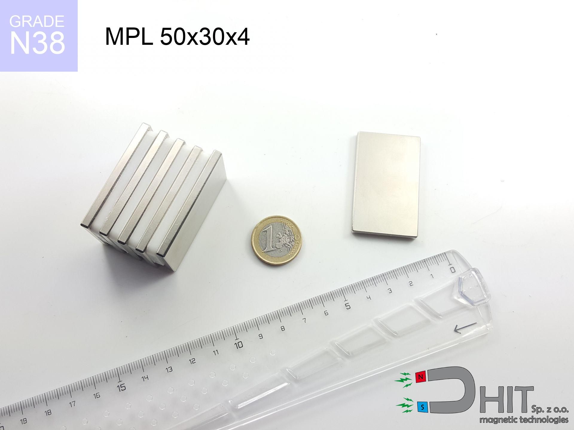
MPL 50x30x4 / N38 - lamellar magnet
lamellar magnet
Catalog no 020497
GTIN/EAN: 5906301814955
length
50 mm [±0,1 mm]
Width
30 mm [±0,1 mm]
Height
4 mm [±0,1 mm]
Weight
45 g
Magnetization Direction
↑ axial
Load capacity
7.57 kg / 74.26 N
Magnetic Induction
120.04 mT / 1200 Gs
Coating
[NiCuNi] Nickel
25.83 ZŁ with VAT / pcs + price for transport
21.00 ZŁ net + 23% VAT / pcs
bulk discounts:
Need more?
Call us now
+48 888 99 98 98
otherwise send us a note via
inquiry form
our website.
Lifting power as well as shape of magnetic components can be verified on our
power calculator.
Orders submitted before 14:00 will be dispatched today!
Detailed specification - MPL 50x30x4 / N38 - lamellar magnet
Specification / characteristics - MPL 50x30x4 / N38 - lamellar magnet
| properties | values |
|---|---|
| Cat. no. | 020497 |
| GTIN/EAN | 5906301814955 |
| Production/Distribution | Dhit sp. z o.o. |
| Country of origin | Poland / China / Germany |
| Customs code | 85059029 |
| length | 50 mm [±0,1 mm] |
| Width | 30 mm [±0,1 mm] |
| Height | 4 mm [±0,1 mm] |
| Weight | 45 g |
| Magnetization Direction | ↑ axial |
| Load capacity ~ ? | 7.57 kg / 74.26 N |
| Magnetic Induction ~ ? | 120.04 mT / 1200 Gs |
| Coating | [NiCuNi] Nickel |
| Manufacturing Tolerance | ±0.1 mm |
Magnetic properties of material N38
| properties | values | units |
|---|---|---|
| remenance Br [min. - max.] ? | 12.2-12.6 | kGs |
| remenance Br [min. - max.] ? | 1220-1260 | mT |
| coercivity bHc ? | 10.8-11.5 | kOe |
| coercivity bHc ? | 860-915 | kA/m |
| actual internal force iHc | ≥ 12 | kOe |
| actual internal force iHc | ≥ 955 | kA/m |
| energy density [min. - max.] ? | 36-38 | BH max MGOe |
| energy density [min. - max.] ? | 287-303 | BH max KJ/m |
| max. temperature ? | ≤ 80 | °C |
Physical properties of sintered neodymium magnets Nd2Fe14B at 20°C
| properties | values | units |
|---|---|---|
| Vickers hardness | ≥550 | Hv |
| Density | ≥7.4 | g/cm3 |
| Curie Temperature TC | 312 - 380 | °C |
| Curie Temperature TF | 593 - 716 | °F |
| Specific resistance | 150 | μΩ⋅cm |
| Bending strength | 250 | MPa |
| Compressive strength | 1000~1100 | MPa |
| Thermal expansion parallel (∥) to orientation (M) | (3-4) x 10-6 | °C-1 |
| Thermal expansion perpendicular (⊥) to orientation (M) | -(1-3) x 10-6 | °C-1 |
| Young's modulus | 1.7 x 10⁴ | kg/mm² |
Technical simulation of the assembly - technical parameters
The following values constitute the result of a physical simulation. Results are based on models for the class Nd2Fe14B. Real-world conditions may differ. Please consider these calculations as a supplementary guide for designers.
Table 1: Static pull force (pull vs gap) - interaction chart
MPL 50x30x4 / N38
| Distance (mm) | Induction (Gauss) / mT | Pull Force (kg/lbs/g/N) | Risk Status |
|---|---|---|---|
| 0 mm |
1200 Gs
120.0 mT
|
7.57 kg / 16.69 LBS
7570.0 g / 74.3 N
|
warning |
| 1 mm |
1176 Gs
117.6 mT
|
7.27 kg / 16.03 LBS
7270.9 g / 71.3 N
|
warning |
| 2 mm |
1144 Gs
114.4 mT
|
6.88 kg / 15.16 LBS
6877.1 g / 67.5 N
|
warning |
| 3 mm |
1105 Gs
110.5 mT
|
6.41 kg / 14.14 LBS
6414.7 g / 62.9 N
|
warning |
| 5 mm |
1012 Gs
101.2 mT
|
5.38 kg / 11.86 LBS
5381.2 g / 52.8 N
|
warning |
| 10 mm |
754 Gs
75.4 mT
|
2.99 kg / 6.59 LBS
2990.1 g / 29.3 N
|
warning |
| 15 mm |
535 Gs
53.5 mT
|
1.50 kg / 3.31 LBS
1503.5 g / 14.7 N
|
safe |
| 20 mm |
376 Gs
37.6 mT
|
0.74 kg / 1.64 LBS
743.3 g / 7.3 N
|
safe |
| 30 mm |
193 Gs
19.3 mT
|
0.20 kg / 0.43 LBS
195.8 g / 1.9 N
|
safe |
| 50 mm |
64 Gs
6.4 mT
|
0.02 kg / 0.05 LBS
21.4 g / 0.2 N
|
safe |
Table 2: Vertical capacity (wall)
MPL 50x30x4 / N38
| Distance (mm) | Friction coefficient | Pull Force (kg/lbs/g/N) |
|---|---|---|
| 0 mm | Stal (~0.2) |
1.51 kg / 3.34 LBS
1514.0 g / 14.9 N
|
| 1 mm | Stal (~0.2) |
1.45 kg / 3.21 LBS
1454.0 g / 14.3 N
|
| 2 mm | Stal (~0.2) |
1.38 kg / 3.03 LBS
1376.0 g / 13.5 N
|
| 3 mm | Stal (~0.2) |
1.28 kg / 2.83 LBS
1282.0 g / 12.6 N
|
| 5 mm | Stal (~0.2) |
1.08 kg / 2.37 LBS
1076.0 g / 10.6 N
|
| 10 mm | Stal (~0.2) |
0.60 kg / 1.32 LBS
598.0 g / 5.9 N
|
| 15 mm | Stal (~0.2) |
0.30 kg / 0.66 LBS
300.0 g / 2.9 N
|
| 20 mm | Stal (~0.2) |
0.15 kg / 0.33 LBS
148.0 g / 1.5 N
|
| 30 mm | Stal (~0.2) |
0.04 kg / 0.09 LBS
40.0 g / 0.4 N
|
| 50 mm | Stal (~0.2) |
0.00 kg / 0.01 LBS
4.0 g / 0.0 N
|
Table 3: Wall mounting (sliding) - behavior on slippery surfaces
MPL 50x30x4 / N38
| Surface type | Friction coefficient / % Mocy | Max load (kg/lbs/g/N) |
|---|---|---|
| Raw steel |
µ = 0.3
30% Nominalnej Siły
|
2.27 kg / 5.01 LBS
2271.0 g / 22.3 N
|
| Painted steel (standard) |
µ = 0.2
20% Nominalnej Siły
|
1.51 kg / 3.34 LBS
1514.0 g / 14.9 N
|
| Oily/slippery steel |
µ = 0.1
10% Nominalnej Siły
|
0.76 kg / 1.67 LBS
757.0 g / 7.4 N
|
| Magnet with anti-slip rubber |
µ = 0.5
50% Nominalnej Siły
|
3.79 kg / 8.34 LBS
3785.0 g / 37.1 N
|
Table 4: Steel thickness (substrate influence) - sheet metal selection
MPL 50x30x4 / N38
| Steel thickness (mm) | % power | Real pull force (kg/lbs/g/N) |
|---|---|---|
| 0.5 mm |
|
0.76 kg / 1.67 LBS
757.0 g / 7.4 N
|
| 1 mm |
|
1.89 kg / 4.17 LBS
1892.5 g / 18.6 N
|
| 2 mm |
|
3.79 kg / 8.34 LBS
3785.0 g / 37.1 N
|
| 3 mm |
|
5.68 kg / 12.52 LBS
5677.5 g / 55.7 N
|
| 5 mm |
|
7.57 kg / 16.69 LBS
7570.0 g / 74.3 N
|
| 10 mm |
|
7.57 kg / 16.69 LBS
7570.0 g / 74.3 N
|
| 11 mm |
|
7.57 kg / 16.69 LBS
7570.0 g / 74.3 N
|
| 12 mm |
|
7.57 kg / 16.69 LBS
7570.0 g / 74.3 N
|
Table 5: Thermal stability (stability) - resistance threshold
MPL 50x30x4 / N38
| Ambient temp. (°C) | Power loss | Remaining pull (kg/lbs/g/N) | Status |
|---|---|---|---|
| 20 °C | 0.0% |
7.57 kg / 16.69 LBS
7570.0 g / 74.3 N
|
OK |
| 40 °C | -2.2% |
7.40 kg / 16.32 LBS
7403.5 g / 72.6 N
|
OK |
| 60 °C | -4.4% |
7.24 kg / 15.95 LBS
7236.9 g / 71.0 N
|
|
| 80 °C | -6.6% |
7.07 kg / 15.59 LBS
7070.4 g / 69.4 N
|
|
| 100 °C | -28.8% |
5.39 kg / 11.88 LBS
5389.8 g / 52.9 N
|
Table 6: Magnet-Magnet interaction (repulsion) - field collision
MPL 50x30x4 / N38
| Gap (mm) | Attraction (kg/lbs) (N-S) | Lateral Force (kg/lbs/g/N) | Repulsion (kg/lbs) (N-N) |
|---|---|---|---|
| 0 mm |
13.32 kg / 29.37 LBS
2 260 Gs
|
2.00 kg / 4.41 LBS
1999 g / 19.6 N
|
N/A |
| 1 mm |
13.09 kg / 28.85 LBS
2 379 Gs
|
1.96 kg / 4.33 LBS
1963 g / 19.3 N
|
11.78 kg / 25.96 LBS
~0 Gs
|
| 2 mm |
12.80 kg / 28.21 LBS
2 353 Gs
|
1.92 kg / 4.23 LBS
1920 g / 18.8 N
|
11.52 kg / 25.39 LBS
~0 Gs
|
| 3 mm |
12.47 kg / 27.49 LBS
2 322 Gs
|
1.87 kg / 4.12 LBS
1870 g / 18.3 N
|
11.22 kg / 24.74 LBS
~0 Gs
|
| 5 mm |
11.71 kg / 25.82 LBS
2 251 Gs
|
1.76 kg / 3.87 LBS
1756 g / 17.2 N
|
10.54 kg / 23.23 LBS
~0 Gs
|
| 10 mm |
9.47 kg / 20.88 LBS
2 024 Gs
|
1.42 kg / 3.13 LBS
1421 g / 13.9 N
|
8.52 kg / 18.79 LBS
~0 Gs
|
| 20 mm |
5.26 kg / 11.60 LBS
1 509 Gs
|
0.79 kg / 1.74 LBS
789 g / 7.7 N
|
4.74 kg / 10.44 LBS
~0 Gs
|
| 50 mm |
0.66 kg / 1.45 LBS
534 Gs
|
0.10 kg / 0.22 LBS
99 g / 1.0 N
|
0.59 kg / 1.31 LBS
~0 Gs
|
| 60 mm |
0.34 kg / 0.76 LBS
386 Gs
|
0.05 kg / 0.11 LBS
52 g / 0.5 N
|
0.31 kg / 0.68 LBS
~0 Gs
|
| 70 mm |
0.19 kg / 0.41 LBS
285 Gs
|
0.03 kg / 0.06 LBS
28 g / 0.3 N
|
0.17 kg / 0.37 LBS
~0 Gs
|
| 80 mm |
0.11 kg / 0.23 LBS
214 Gs
|
0.02 kg / 0.03 LBS
16 g / 0.2 N
|
0.10 kg / 0.21 LBS
~0 Gs
|
| 90 mm |
0.06 kg / 0.14 LBS
164 Gs
|
0.01 kg / 0.02 LBS
9 g / 0.1 N
|
0.06 kg / 0.12 LBS
~0 Gs
|
| 100 mm |
0.04 kg / 0.08 LBS
128 Gs
|
0.01 kg / 0.01 LBS
6 g / 0.1 N
|
0.03 kg / 0.07 LBS
~0 Gs
|
Table 7: Hazards (implants) - precautionary measures
MPL 50x30x4 / N38
| Object / Device | Limit (Gauss) / mT | Safe distance |
|---|---|---|
| Pacemaker | 5 Gs (0.5 mT) | 13.0 cm |
| Hearing aid | 10 Gs (1.0 mT) | 10.5 cm |
| Mechanical watch | 20 Gs (2.0 mT) | 8.0 cm |
| Phone / Smartphone | 40 Gs (4.0 mT) | 6.5 cm |
| Remote | 50 Gs (5.0 mT) | 6.0 cm |
| Payment card | 400 Gs (40.0 mT) | 2.0 cm |
| HDD hard drive | 600 Gs (60.0 mT) | 1.5 cm |
Table 8: Collisions (cracking risk) - warning
MPL 50x30x4 / N38
| Start from (mm) | Speed (km/h) | Energy (J) | Predicted outcome |
|---|---|---|---|
| 10 mm |
15.99 km/h
(4.44 m/s)
|
0.44 J | |
| 30 mm |
23.02 km/h
(6.39 m/s)
|
0.92 J | |
| 50 mm |
29.30 km/h
(8.14 m/s)
|
1.49 J | |
| 100 mm |
41.37 km/h
(11.49 m/s)
|
2.97 J |
Table 9: Anti-corrosion coating durability
MPL 50x30x4 / N38
| Technical parameter | Value / Description |
|---|---|
| Coating type | [NiCuNi] Nickel |
| Layer structure | Nickel - Copper - Nickel |
| Layer thickness | 10-20 µm |
| Salt spray test (SST) ? | 24 h |
| Recommended environment | Indoors only (dry) |
Table 10: Construction data (Flux)
MPL 50x30x4 / N38
| Parameter | Value | SI Unit / Description |
|---|---|---|
| Magnetic Flux | 22 399 Mx | 224.0 µWb |
| Pc Coefficient | 0.14 | Low (Flat) |
Table 11: Physics of underwater searching
MPL 50x30x4 / N38
| Environment | Effective steel pull | Effect |
|---|---|---|
| Air (land) | 7.57 kg | Standard |
| Water (riverbed) |
8.67 kg
(+1.10 kg buoyancy gain)
|
+14.5% |
1. Sliding resistance
*Warning: On a vertical wall, the magnet retains just a fraction of its perpendicular strength.
2. Steel thickness impact
*Thin steel (e.g. computer case) severely weakens the holding force.
3. Thermal stability
*For N38 material, the safety limit is 80°C.
4. Demagnetization curve and operating point (B-H)
chart generated for the permeance coefficient Pc (Permeance Coefficient) = 0.14
The chart above illustrates the magnetic characteristics of the material within the second quadrant of the hysteresis loop. The solid red line represents the demagnetization curve (material potential), while the dashed blue line is the load line based on the magnet's geometry. The Pc (Permeance Coefficient), also known as the load line slope, is a dimensionless value that describes the relationship between the magnet's shape and its magnetic stability. The intersection of these two lines (the black dot) is the operating point — it determines the actual magnetic flux density generated by the magnet in this specific configuration. A higher Pc value means the magnet is more 'slender' (tall relative to its area), resulting in a higher operating point and better resistance to irreversible demagnetization caused by external fields or temperature. A value of 0.42 is relatively low (typical for flat magnets), meaning the operating point is closer to the 'knee' of the curve — caution is advised when operating at temperatures near the maximum limit to avoid strength loss.
Chemical composition
| iron (Fe) | 64% – 68% |
| neodymium (Nd) | 29% – 32% |
| boron (B) | 1.1% – 1.2% |
| dysprosium (Dy) | 0.5% – 2.0% |
| coating (Ni-Cu-Ni) | < 0.05% |
Environmental data
| recyclability (EoL) | 100% |
| recycled raw materials | ~10% (pre-cons) |
| carbon footprint | low / zredukowany |
| waste code (EWC) | 16 02 16 |
Other proposals


![BM 950x180x70 [4x M8] - magnetic beam](https://cdn3.dhit.pl/graphics/products/bm-950x180x70-4x-m8-ves.jpg "BM 950x180x70 [4x M8] - magnetic beam")

Pros as well as cons of neodymium magnets.
Advantages
- They do not lose strength, even over nearly ten years – the decrease in power is only ~1% (based on measurements),
- Magnets perfectly protect themselves against loss of magnetization caused by ambient magnetic noise,
- Thanks to the smooth finish, the surface of nickel, gold-plated, or silver-plated gives an visually attractive appearance,
- Magnets are characterized by very high magnetic induction on the outer layer,
- Neodymium magnets are characterized by very high magnetic induction on the magnet surface and are able to act (depending on the form) even at a temperature of 230°C or more...
- Possibility of detailed creating and adjusting to concrete needs,
- Significant place in electronics industry – they are used in hard drives, brushless drives, diagnostic systems, as well as multitasking production systems.
- Compactness – despite small sizes they provide effective action, making them ideal for precision applications
Weaknesses
- They are prone to damage upon heavy impacts. To avoid cracks, it is worth securing magnets in a protective case. Such protection not only protects the magnet but also increases its resistance to damage
- Neodymium magnets demagnetize when exposed to high temperatures. After reaching 80°C, many of them experience permanent weakening of power (a factor is the shape and dimensions of the magnet). We offer magnets specially adapted to work at temperatures up to 230°C marked [AH], which are extremely resistant to heat
- Magnets exposed to a humid environment can corrode. Therefore while using outdoors, we suggest using waterproof magnets made of rubber, plastic or other material protecting against moisture
- Due to limitations in creating threads and complicated shapes in magnets, we propose using cover - magnetic mount.
- Potential hazard to health – tiny shards of magnets pose a threat, when accidentally swallowed, which becomes key in the aspect of protecting the youngest. It is also worth noting that small components of these products can complicate diagnosis medical in case of swallowing.
- With mass production the cost of neodymium magnets is economically unviable,
Lifting parameters
Maximum lifting capacity of the magnet – what contributes to it?
- on a base made of structural steel, optimally conducting the magnetic flux
- possessing a massiveness of minimum 10 mm to avoid saturation
- with an ideally smooth contact surface
- without the slightest insulating layer between the magnet and steel
- for force acting at a right angle (in the magnet axis)
- at room temperature
Magnet lifting force in use – key factors
- Gap between surfaces – every millimeter of separation (caused e.g. by veneer or dirt) diminishes the pulling force, often by half at just 0.5 mm.
- Pull-off angle – note that the magnet holds strongest perpendicularly. Under sliding down, the capacity drops drastically, often to levels of 20-30% of the maximum value.
- Substrate thickness – to utilize 100% power, the steel must be sufficiently thick. Paper-thin metal limits the lifting capacity (the magnet "punches through" it).
- Material composition – different alloys reacts the same. Alloy additives weaken the interaction with the magnet.
- Surface condition – ground elements guarantee perfect abutment, which increases field saturation. Rough surfaces weaken the grip.
- Thermal conditions – neodymium magnets have a negative temperature coefficient. At higher temperatures they lose power, and at low temperatures they can be stronger (up to a certain limit).
Holding force was measured on a smooth steel plate of 20 mm thickness, when a perpendicular force was applied, however under parallel forces the lifting capacity is smaller. Moreover, even a slight gap between the magnet’s surface and the plate lowers the load capacity.
Warnings
Allergic reactions
Medical facts indicate that nickel (standard magnet coating) is a potent allergen. If your skin reacts to metals, prevent direct skin contact or choose coated magnets.
Health Danger
Warning for patients: Powerful magnets disrupt medical devices. Maintain minimum 30 cm distance or ask another person to work with the magnets.
GPS Danger
Navigation devices and mobile phones are extremely susceptible to magnetism. Direct contact with a strong magnet can decalibrate the internal compass in your phone.
Do not overheat magnets
Regular neodymium magnets (N-type) lose power when the temperature surpasses 80°C. The loss of strength is permanent.
Finger safety
Risk of injury: The pulling power is so immense that it can result in hematomas, pinching, and broken bones. Use thick gloves.
Fire risk
Powder produced during cutting of magnets is self-igniting. Avoid drilling into magnets without proper cooling and knowledge.
Danger to the youngest
Product intended for adults. Small elements pose a choking risk, causing intestinal necrosis. Keep out of reach of children and animals.
Protect data
Intense magnetic fields can erase data on payment cards, HDDs, and storage devices. Stay away of at least 10 cm.
Shattering risk
Despite the nickel coating, neodymium is brittle and cannot withstand shocks. Do not hit, as the magnet may crumble into hazardous fragments.
Do not underestimate power
Be careful. Neodymium magnets act from a distance and connect with huge force, often faster than you can move away.
Tabela kosztu i czasu dostawy
Płatność przed wysyłką:

GLS kurier
Przesyłka będzie u Ciebie za 2-3 dni
14.99 ZŁ

InPost Paczkomaty 24/7
Przesyłka będzie u Ciebie za 1-2 dni
12.30 ZŁ
Płatność przy odbiorze (pobranie):
GLS kurier
Przesyłka będzie u Ciebie za 1-2 dni
23.00 ZŁ
Rate the product
Your rating