
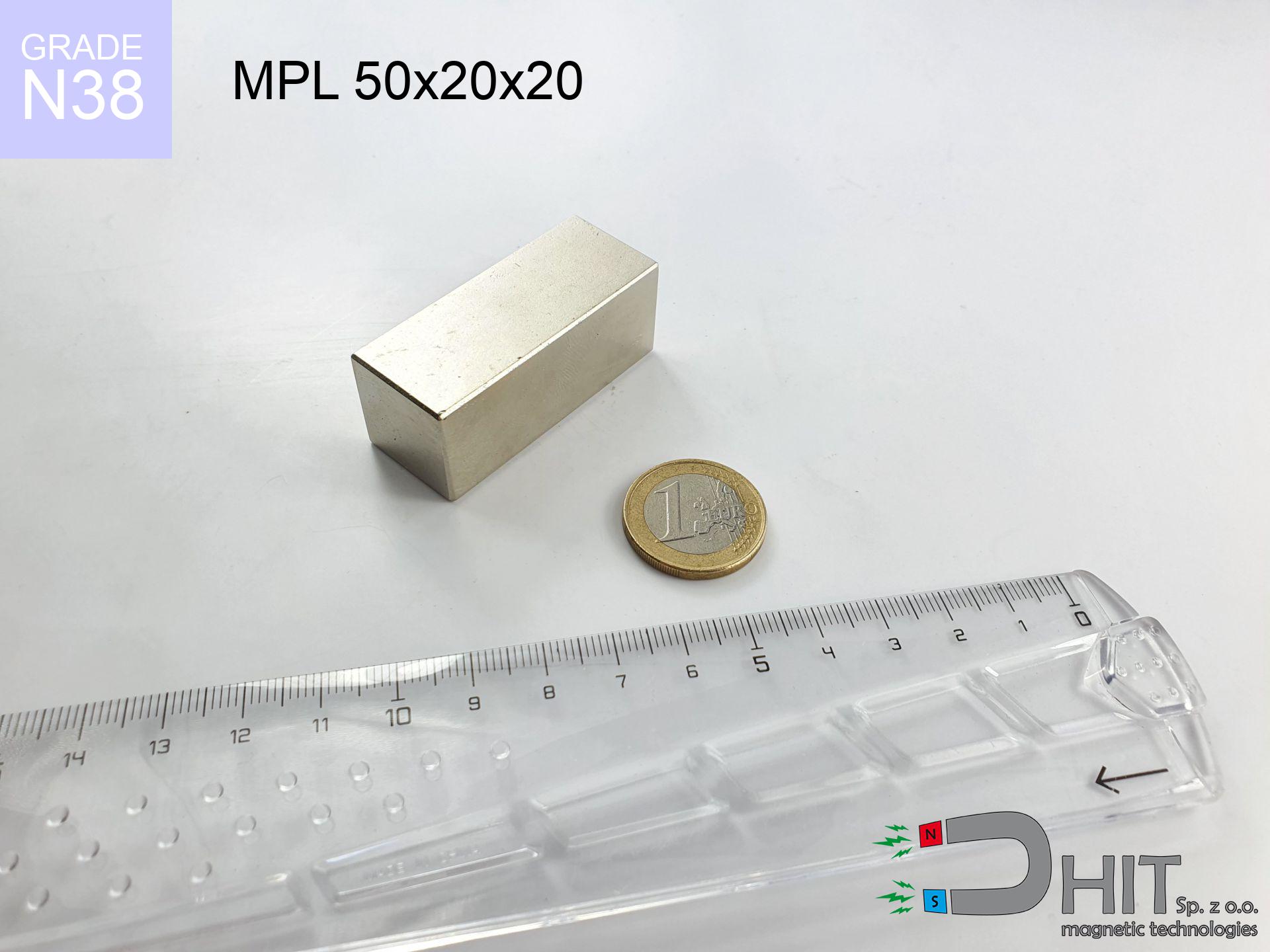
MPL 50x20x20 / N38 - lamellar magnet
lamellar magnet
Catalog no 020166
GTIN/EAN: 5906301811725
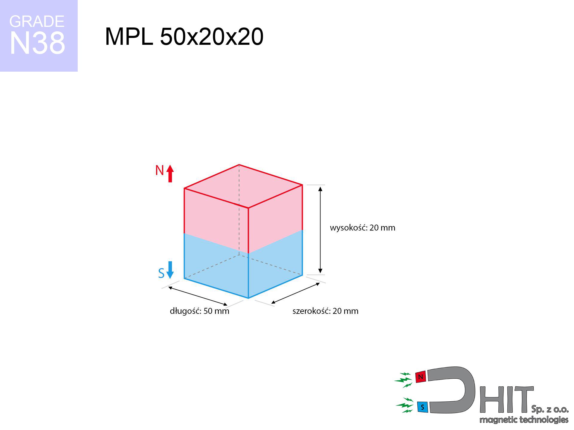
length
50 mm [±0,1 mm]
Width
20 mm [±0,1 mm]
Height
20 mm [±0,1 mm]
Weight
150 g
Magnetization Direction
↑ axial
Load capacity
42.18 kg / 413.81 N
Magnetic Induction
478.99 mT / 4790 Gs
Coating
[NiCuNi] Nickel
47.32 ZŁ with VAT / pcs + price for transport
38.47 ZŁ net + 23% VAT / pcs
bulk discounts:
Need more?Engineering report for this magnet
Full PDF analysis: pull and shear force, effect of distance, temperature and plate thickness, safety distances and the demagnetization curve.
Contact us by phone
+48 22 499 98 98
if you prefer get in touch through
our online form
the contact form page.
Specifications and structure of neodymium magnets can be reviewed using our
online calculation tool.
Order by 14:00 and we’ll ship today!
Product card - MPL 50x20x20 / N38 - lamellar magnet
Specification / characteristics - MPL 50x20x20 / N38 - lamellar magnet
| properties | values |
|---|---|
| Cat. no. | 020166 |
| GTIN/EAN | 5906301811725 |
| Production/Distribution | Dhit sp. z o.o. |
| Country of origin | Poland / China / Germany |
| Customs code | 85059029 |
| length | 50 mm [±0,1 mm] |
| Width | 20 mm [±0,1 mm] |
| Height | 20 mm [±0,1 mm] |
| Weight | 150 g |
| Magnetization Direction | ↑ axial |
| Load capacity ~ ? | 42.18 kg / 413.81 N |
| Magnetic Induction ~ ? | 478.99 mT / 4790 Gs |
| Coating | [NiCuNi] Nickel |
| Manufacturing Tolerance | ±0.1 mm |
Magnetic properties of material N38
| properties | values | units |
|---|---|---|
| remenance Br [min. - max.] ? | 12.2-12.6 | kGs |
| remenance Br [min. - max.] ? | 1220-1260 | mT |
| coercivity bHc ? | 10.8-11.5 | kOe |
| coercivity bHc ? | 860-915 | kA/m |
| actual internal force iHc | ≥ 12 | kOe |
| actual internal force iHc | ≥ 955 | kA/m |
| energy density [min. - max.] ? | 36-38 | BH max MGOe |
| energy density [min. - max.] ? | 287-303 | BH max KJ/m |
| max. temperature ? | ≤ 80 | °C |
Physical properties of sintered neodymium magnets Nd2Fe14B at 20°C
| properties | values | units |
|---|---|---|
| Vickers hardness | ≥550 | Hv |
| Density | ≥7.4 | g/cm3 |
| Curie Temperature TC | 312 - 380 | °C |
| Curie Temperature TF | 593 - 716 | °F |
| Specific resistance | 150 | μΩ⋅cm |
| Bending strength | 250 | MPa |
| Compressive strength | 1000~1100 | MPa |
| Thermal expansion parallel (∥) to orientation (M) | (3-4) x 10-6 | °C-1 |
| Thermal expansion perpendicular (⊥) to orientation (M) | -(1-3) x 10-6 | °C-1 |
| Young's modulus | 1.7 x 10⁴ | kg/mm² |
Technical analysis of the assembly - data
These values constitute the direct effect of a engineering analysis. Results were calculated on models for the material Nd2Fe14B. Operational conditions may deviate from the simulation results. Treat these data as a reference point during assembly planning.
Table 1: Static force (pull vs distance) - power drop
MPL 50x20x20 / N38
| Distance (mm) | Induction (Gauss) / mT | Pull Force (kg/lbs/g/N) | Risk Status |
|---|---|---|---|
| 0 mm |
4789 Gs
478.9 mT
|
42.18 kg / 92.99 LBS
42180.0 g / 413.8 N
|
crushing |
| 1 mm |
4452 Gs
445.2 mT
|
36.46 kg / 80.38 LBS
36461.5 g / 357.7 N
|
crushing |
| 2 mm |
4114 Gs
411.4 mT
|
31.13 kg / 68.62 LBS
31126.5 g / 305.4 N
|
crushing |
| 3 mm |
3784 Gs
378.4 mT
|
26.34 kg / 58.06 LBS
26336.3 g / 258.4 N
|
crushing |
| 5 mm |
3173 Gs
317.3 mT
|
18.52 kg / 40.84 LBS
18523.4 g / 181.7 N
|
crushing |
| 10 mm |
2022 Gs
202.2 mT
|
7.52 kg / 16.59 LBS
7522.9 g / 73.8 N
|
warning |
| 15 mm |
1324 Gs
132.4 mT
|
3.22 kg / 7.10 LBS
3222.6 g / 31.6 N
|
warning |
| 20 mm |
899 Gs
89.9 mT
|
1.49 kg / 3.28 LBS
1487.5 g / 14.6 N
|
low risk |
| 30 mm |
458 Gs
45.8 mT
|
0.39 kg / 0.85 LBS
385.8 g / 3.8 N
|
low risk |
| 50 mm |
159 Gs
15.9 mT
|
0.05 kg / 0.10 LBS
46.4 g / 0.5 N
|
low risk |
Table 2: Shear hold (vertical surface)
MPL 50x20x20 / N38
| Distance (mm) | Friction coefficient | Pull Force (kg/lbs/g/N) |
|---|---|---|
| 0 mm | Stal (~0.2) |
8.44 kg / 18.60 LBS
8436.0 g / 82.8 N
|
| 1 mm | Stal (~0.2) |
7.29 kg / 16.08 LBS
7292.0 g / 71.5 N
|
| 2 mm | Stal (~0.2) |
6.23 kg / 13.73 LBS
6226.0 g / 61.1 N
|
| 3 mm | Stal (~0.2) |
5.27 kg / 11.61 LBS
5268.0 g / 51.7 N
|
| 5 mm | Stal (~0.2) |
3.70 kg / 8.17 LBS
3704.0 g / 36.3 N
|
| 10 mm | Stal (~0.2) |
1.50 kg / 3.32 LBS
1504.0 g / 14.8 N
|
| 15 mm | Stal (~0.2) |
0.64 kg / 1.42 LBS
644.0 g / 6.3 N
|
| 20 mm | Stal (~0.2) |
0.30 kg / 0.66 LBS
298.0 g / 2.9 N
|
| 30 mm | Stal (~0.2) |
0.08 kg / 0.17 LBS
78.0 g / 0.8 N
|
| 50 mm | Stal (~0.2) |
0.01 kg / 0.02 LBS
10.0 g / 0.1 N
|
Table 3: Vertical assembly (shearing) - vertical pull
MPL 50x20x20 / N38
| Surface type | Friction coefficient / % Mocy | Max load (kg/lbs/g/N) |
|---|---|---|
| Raw steel |
µ = 0.3
30% Nominalnej Siły
|
12.65 kg / 27.90 LBS
12654.0 g / 124.1 N
|
| Painted steel (standard) |
µ = 0.2
20% Nominalnej Siły
|
8.44 kg / 18.60 LBS
8436.0 g / 82.8 N
|
| Oily/slippery steel |
µ = 0.1
10% Nominalnej Siły
|
4.22 kg / 9.30 LBS
4218.0 g / 41.4 N
|
| Magnet with anti-slip rubber |
µ = 0.5
50% Nominalnej Siły
|
21.09 kg / 46.50 LBS
21090.0 g / 206.9 N
|
Table 4: Material efficiency (substrate influence) - sheet metal selection
MPL 50x20x20 / N38
| Steel thickness (mm) | % power | Real pull force (kg/lbs/g/N) |
|---|---|---|
| 0.5 mm |
|
2.11 kg / 4.65 LBS
2109.0 g / 20.7 N
|
| 1 mm |
|
5.27 kg / 11.62 LBS
5272.5 g / 51.7 N
|
| 2 mm |
|
10.55 kg / 23.25 LBS
10545.0 g / 103.4 N
|
| 3 mm |
|
15.82 kg / 34.87 LBS
15817.5 g / 155.2 N
|
| 5 mm |
|
26.36 kg / 58.12 LBS
26362.5 g / 258.6 N
|
| 10 mm |
|
42.18 kg / 92.99 LBS
42180.0 g / 413.8 N
|
| 11 mm |
|
42.18 kg / 92.99 LBS
42180.0 g / 413.8 N
|
| 12 mm |
|
42.18 kg / 92.99 LBS
42180.0 g / 413.8 N
|
Table 5: Thermal stability (stability) - resistance threshold
MPL 50x20x20 / N38
| Ambient temp. (°C) | Power loss | Remaining pull (kg/lbs/g/N) | Status |
|---|---|---|---|
| 20 °C | 0.0% |
42.18 kg / 92.99 LBS
42180.0 g / 413.8 N
|
OK |
| 40 °C | -2.2% |
41.25 kg / 90.95 LBS
41252.0 g / 404.7 N
|
OK |
| 60 °C | -4.4% |
40.32 kg / 88.90 LBS
40324.1 g / 395.6 N
|
OK |
| 80 °C | -6.6% |
39.40 kg / 86.85 LBS
39396.1 g / 386.5 N
|
|
| 100 °C | -28.8% |
30.03 kg / 66.21 LBS
30032.2 g / 294.6 N
|
Table 6: Two magnets (attraction) - forces in the system
MPL 50x20x20 / N38
| Gap (mm) | Attraction (kg/lbs) (N-S) | Shear Force (kg/lbs/g/N) | Repulsion (kg/lbs) (N-N) |
|---|---|---|---|
| 0 mm |
141.37 kg / 311.66 LBS
5 687 Gs
|
21.21 kg / 46.75 LBS
21205 g / 208.0 N
|
N/A |
| 1 mm |
131.73 kg / 290.41 LBS
9 245 Gs
|
19.76 kg / 43.56 LBS
19759 g / 193.8 N
|
118.55 kg / 261.37 LBS
~0 Gs
|
| 2 mm |
122.20 kg / 269.41 LBS
8 904 Gs
|
18.33 kg / 40.41 LBS
18330 g / 179.8 N
|
109.98 kg / 242.47 LBS
~0 Gs
|
| 3 mm |
113.05 kg / 249.23 LBS
8 564 Gs
|
16.96 kg / 37.38 LBS
16957 g / 166.4 N
|
101.74 kg / 224.31 LBS
~0 Gs
|
| 5 mm |
96.05 kg / 211.76 LBS
7 894 Gs
|
14.41 kg / 31.76 LBS
14408 g / 141.3 N
|
86.45 kg / 190.58 LBS
~0 Gs
|
| 10 mm |
62.08 kg / 136.87 LBS
6 347 Gs
|
9.31 kg / 20.53 LBS
9312 g / 91.4 N
|
55.87 kg / 123.18 LBS
~0 Gs
|
| 20 mm |
25.21 kg / 55.59 LBS
4 045 Gs
|
3.78 kg / 8.34 LBS
3782 g / 37.1 N
|
22.69 kg / 50.03 LBS
~0 Gs
|
| 50 mm |
2.46 kg / 5.43 LBS
1 264 Gs
|
0.37 kg / 0.81 LBS
370 g / 3.6 N
|
2.22 kg / 4.89 LBS
~0 Gs
|
| 60 mm |
1.29 kg / 2.85 LBS
916 Gs
|
0.19 kg / 0.43 LBS
194 g / 1.9 N
|
1.16 kg / 2.57 LBS
~0 Gs
|
| 70 mm |
0.71 kg / 1.58 LBS
681 Gs
|
0.11 kg / 0.24 LBS
107 g / 1.1 N
|
0.64 kg / 1.42 LBS
~0 Gs
|
| 80 mm |
0.41 kg / 0.91 LBS
518 Gs
|
0.06 kg / 0.14 LBS
62 g / 0.6 N
|
0.37 kg / 0.82 LBS
~0 Gs
|
| 90 mm |
0.25 kg / 0.55 LBS
402 Gs
|
0.04 kg / 0.08 LBS
37 g / 0.4 N
|
0.22 kg / 0.49 LBS
~0 Gs
|
| 100 mm |
0.16 kg / 0.34 LBS
318 Gs
|
0.02 kg / 0.05 LBS
23 g / 0.2 N
|
0.14 kg / 0.31 LBS
~0 Gs
|
Table 7: Protective zones (implants) - precautionary measures
MPL 50x20x20 / N38
| Object / Device | Limit (Gauss) / mT | Safe distance |
|---|---|---|
| Pacemaker | 5 Gs (0.5 mT) | 19.0 cm |
| Hearing aid | 10 Gs (1.0 mT) | 15.0 cm |
| Timepiece | 20 Gs (2.0 mT) | 11.5 cm |
| Mobile device | 40 Gs (4.0 mT) | 9.0 cm |
| Car key | 50 Gs (5.0 mT) | 8.5 cm |
| Payment card | 400 Gs (40.0 mT) | 3.5 cm |
| HDD hard drive | 600 Gs (60.0 mT) | 3.0 cm |
Table 8: Collisions (kinetic energy) - warning
MPL 50x20x20 / N38
| Start from (mm) | Speed (km/h) | Energy (J) | Predicted outcome |
|---|---|---|---|
| 10 mm |
18.74 km/h
(5.21 m/s)
|
2.03 J | |
| 30 mm |
20.65 km/h
(5.74 m/s)
|
2.47 J | |
| 50 mm |
20.78 km/h
(5.77 m/s)
|
2.50 J | |
| 100 mm |
20.80 km/h
(5.78 m/s)
|
2.50 J |
Table 9: Coating parameters (durability)
MPL 50x20x20 / N38
| Technical parameter | Value / Description |
|---|---|
| Coating type | [NiCuNi] Nickel |
| Layer structure | Nickel - Copper - Nickel |
| Layer thickness | 10-20 µm |
| Salt spray test (SST) ? | 24 h |
| Recommended environment | Indoors only (dry) |
Table 10: Electrical data (Pc)
MPL 50x20x20 / N38
| Parameter | Value | SI Unit / Description |
|---|---|---|
| Magnetic Flux | 46 654 Mx | 466.5 µWb |
| Pc Coefficient | 0.63 | High (Stable) |
Table 11: Underwater work (magnet fishing)
MPL 50x20x20 / N38
| Environment | Effective steel pull | Effect |
|---|---|---|
| Air (land) | 42.18 kg | Standard |
| Water (riverbed) |
48.30 kg
(+6.12 kg buoyancy gain)
|
+14.5% |
1. Vertical hold
*Note: On a vertical surface, the magnet holds merely ~20% of its nominal pull.
2. Plate thickness effect
*Thin steel (e.g. computer case) significantly reduces the holding force.
3. Power loss vs temp
*For N38 grade, the max working temp is 80°C.
4. Demagnetization curve and operating point (B-H)
chart generated for the permeance coefficient Pc (Permeance Coefficient) = 0.63
The chart above illustrates the magnetic characteristics of the material within the second quadrant of the hysteresis loop. The solid red line represents the demagnetization curve (material potential), while the dashed blue line is the load line based on the magnet's geometry. The Pc (Permeance Coefficient), also known as the load line slope, is a dimensionless value that describes the relationship between the magnet's shape and its magnetic stability. The intersection of these two lines (the black dot) is the operating point — it determines the actual magnetic flux density generated by the magnet in this specific configuration. A higher Pc value means the magnet is more 'slender' (tall relative to its area), resulting in a higher operating point and better resistance to irreversible demagnetization caused by external fields or temperature. A value of 0.42 is relatively low (typical for flat magnets), meaning the operating point is closer to the 'knee' of the curve — caution is advised when operating at temperatures near the maximum limit to avoid strength loss.
Elemental analysis
| iron (Fe) | 64% – 68% |
| neodymium (Nd) | 29% – 32% |
| boron (B) | 1.1% – 1.2% |
| dysprosium (Dy) | 0.5% – 2.0% |
| coating (Ni-Cu-Ni) | < 0.05% |
Environmental data
| recyclability (EoL) | 100% |
| recycled raw materials | ~10% (pre-cons) |
| carbon footprint | low / zredukowany |
| waste code (EWC) | 16 02 16 |
Other deals


Strengths and weaknesses of Nd2Fe14B magnets.
Strengths
- They virtually do not lose strength, because even after 10 years the decline in efficiency is only ~1% (according to literature),
- They are extremely resistant to demagnetization induced by external magnetic fields,
- Thanks to the reflective finish, the layer of nickel, gold, or silver gives an elegant appearance,
- The surface of neodymium magnets generates a powerful magnetic field – this is a distinguishing feature,
- Neodymium magnets are characterized by very high magnetic induction on the magnet surface and are able to act (depending on the shape) even at a temperature of 230°C or more...
- Possibility of precise machining as well as adapting to individual conditions,
- Huge importance in advanced technology sectors – they are used in magnetic memories, electric drive systems, medical equipment, and other advanced devices.
- Compactness – despite small sizes they generate large force, making them ideal for precision applications
Cons
- Susceptibility to cracking is one of their disadvantages. Upon intense impact they can break. We advise keeping them in a steel housing, which not only secures them against impacts but also raises their durability
- Neodymium magnets lose power when exposed to high temperatures. After reaching 80°C, many of them experience permanent weakening of power (a factor is the shape and dimensions of the magnet). We offer magnets specially adapted to work at temperatures up to 230°C marked [AH], which are extremely resistant to heat
- When exposed to humidity, magnets start to rust. For applications outside, it is recommended to use protective magnets, such as those in rubber or plastics, which secure oxidation as well as corrosion.
- Due to limitations in producing threads and complicated forms in magnets, we recommend using a housing - magnetic holder.
- Possible danger resulting from small fragments of magnets pose a threat, in case of ingestion, which gains importance in the context of child health protection. Additionally, small elements of these products can disrupt the diagnostic process medical in case of swallowing.
- With mass production the cost of neodymium magnets is economically unviable,
Holding force characteristics
Maximum lifting capacity of the magnet – what contributes to it?
- with the use of a sheet made of special test steel, ensuring full magnetic saturation
- whose transverse dimension reaches at least 10 mm
- with a surface free of scratches
- with total lack of distance (without paint)
- for force acting at a right angle (in the magnet axis)
- at room temperature
Impact of factors on magnetic holding capacity in practice
- Clearance – the presence of any layer (rust, dirt, gap) interrupts the magnetic circuit, which reduces capacity steeply (even by 50% at 0.5 mm).
- Force direction – note that the magnet holds strongest perpendicularly. Under sliding down, the capacity drops drastically, often to levels of 20-30% of the maximum value.
- Wall thickness – thin material does not allow full use of the magnet. Magnetic flux penetrates through instead of generating force.
- Steel type – low-carbon steel gives the best results. Higher carbon content decrease magnetic permeability and holding force.
- Surface structure – the more even the plate, the better the adhesion and higher the lifting capacity. Roughness creates an air distance.
- Thermal factor – hot environment weakens pulling force. Exceeding the limit temperature can permanently demagnetize the magnet.
Lifting capacity was measured with the use of a polished steel plate of suitable thickness (min. 20 mm), under vertically applied force, whereas under attempts to slide the magnet the holding force is lower. Additionally, even a minimal clearance between the magnet’s surface and the plate lowers the holding force.
H&S for magnets
Bone fractures
Big blocks can break fingers in a fraction of a second. Do not put your hand betwixt two attracting surfaces.
Risk of cracking
Neodymium magnets are sintered ceramics, which means they are fragile like glass. Collision of two magnets leads to them breaking into small pieces.
No play value
Absolutely store magnets away from children. Ingestion danger is significant, and the consequences of magnets connecting inside the body are fatal.
Safe distance
Data protection: Strong magnets can ruin payment cards and sensitive devices (pacemakers, medical aids, timepieces).
Allergy Warning
It is widely known that nickel (the usual finish) is a strong allergen. If your skin reacts to metals, refrain from touching magnets with bare hands and choose encased magnets.
GPS and phone interference
A strong magnetic field disrupts the functioning of compasses in phones and GPS navigation. Do not bring magnets close to a smartphone to prevent breaking the sensors.
ICD Warning
Warning for patients: Strong magnetic fields disrupt medical devices. Keep at least 30 cm distance or ask another person to handle the magnets.
Handling rules
Exercise caution. Neodymium magnets act from a distance and connect with massive power, often faster than you can move away.
Heat warning
Monitor thermal conditions. Exposing the magnet above 80 degrees Celsius will permanently weaken its magnetic structure and strength.
Dust is flammable
Powder created during cutting of magnets is self-igniting. Do not drill into magnets unless you are an expert.
Tabela kosztu i czasu dostawy
Płatność przed wysyłką:

GLS kurier
Przesyłka będzie u Ciebie za 2-3 dni
14.99 ZŁ

InPost Paczkomaty 24/7
Przesyłka będzie u Ciebie za 1-2 dni
12.30 ZŁ
Płatność przy odbiorze (pobranie):
GLS kurier
Przesyłka będzie u Ciebie za 1-2 dni
23.00 ZŁ
Rate the product
Your rating