

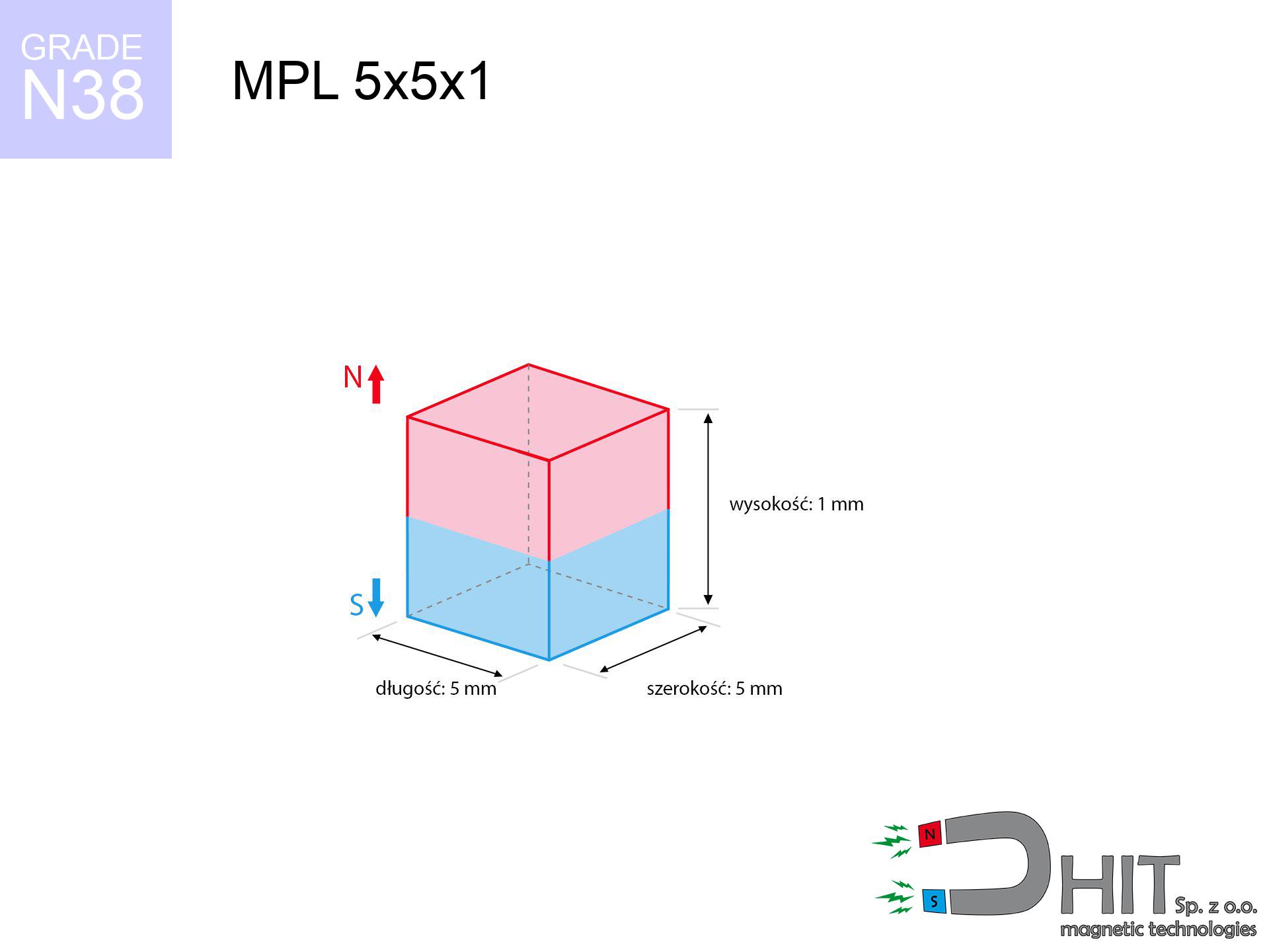
MPL 5x5x1 / N38 - lamellar magnet
lamellar magnet
Catalog no 020170
GTIN/EAN: 5906301811763
length
5 mm [±0,1 mm]
Width
5 mm [±0,1 mm]
Height
1 mm [±0,1 mm]
Weight
0.19 g
Magnetization Direction
↑ axial
Load capacity
0.34 kg / 3.30 N
Magnetic Induction
209.53 mT / 2095 Gs
Coating
[NiCuNi] Nickel
0.1845 ZŁ with VAT / pcs + price for transport
0.1500 ZŁ net + 23% VAT / pcs
bulk discounts:
Need more?
Call us now
+48 22 499 98 98
otherwise contact us through
contact form
through our site.
Parameters and appearance of a neodymium magnet can be checked using our
online calculation tool.
Same-day processing for orders placed before 14:00.
Technical parameters of the product - MPL 5x5x1 / N38 - lamellar magnet
Specification / characteristics - MPL 5x5x1 / N38 - lamellar magnet
| properties | values |
|---|---|
| Cat. no. | 020170 |
| GTIN/EAN | 5906301811763 |
| Production/Distribution | Dhit sp. z o.o. |
| Country of origin | Poland / China / Germany |
| Customs code | 85059029 |
| length | 5 mm [±0,1 mm] |
| Width | 5 mm [±0,1 mm] |
| Height | 1 mm [±0,1 mm] |
| Weight | 0.19 g |
| Magnetization Direction | ↑ axial |
| Load capacity ~ ? | 0.34 kg / 3.30 N |
| Magnetic Induction ~ ? | 209.53 mT / 2095 Gs |
| Coating | [NiCuNi] Nickel |
| Manufacturing Tolerance | ±0.1 mm |
Magnetic properties of material N38
| properties | values | units |
|---|---|---|
| remenance Br [min. - max.] ? | 12.2-12.6 | kGs |
| remenance Br [min. - max.] ? | 1220-1260 | mT |
| coercivity bHc ? | 10.8-11.5 | kOe |
| coercivity bHc ? | 860-915 | kA/m |
| actual internal force iHc | ≥ 12 | kOe |
| actual internal force iHc | ≥ 955 | kA/m |
| energy density [min. - max.] ? | 36-38 | BH max MGOe |
| energy density [min. - max.] ? | 287-303 | BH max KJ/m |
| max. temperature ? | ≤ 80 | °C |
Physical properties of sintered neodymium magnets Nd2Fe14B at 20°C
| properties | values | units |
|---|---|---|
| Vickers hardness | ≥550 | Hv |
| Density | ≥7.4 | g/cm3 |
| Curie Temperature TC | 312 - 380 | °C |
| Curie Temperature TF | 593 - 716 | °F |
| Specific resistance | 150 | μΩ⋅cm |
| Bending strength | 250 | MPa |
| Compressive strength | 1000~1100 | MPa |
| Thermal expansion parallel (∥) to orientation (M) | (3-4) x 10-6 | °C-1 |
| Thermal expansion perpendicular (⊥) to orientation (M) | -(1-3) x 10-6 | °C-1 |
| Young's modulus | 1.7 x 10⁴ | kg/mm² |
Engineering simulation of the product - technical parameters
The following data constitute the outcome of a physical analysis. Results are based on models for the class Nd2Fe14B. Real-world performance might slightly differ. Treat these data as a supplementary guide for designers.
Table 1: Static force (pull vs gap) - interaction chart
MPL 5x5x1 / N38
| Distance (mm) | Induction (Gauss) / mT | Pull Force (kg/lbs/g/N) | Risk Status |
|---|---|---|---|
| 0 mm |
2094 Gs
209.4 mT
|
0.34 kg / 0.75 pounds
340.0 g / 3.3 N
|
safe |
| 1 mm |
1514 Gs
151.4 mT
|
0.18 kg / 0.39 pounds
177.8 g / 1.7 N
|
safe |
| 2 mm |
922 Gs
92.2 mT
|
0.07 kg / 0.15 pounds
65.9 g / 0.6 N
|
safe |
| 3 mm |
543 Gs
54.3 mT
|
0.02 kg / 0.05 pounds
22.9 g / 0.2 N
|
safe |
| 5 mm |
209 Gs
20.9 mT
|
0.00 kg / 0.01 pounds
3.4 g / 0.0 N
|
safe |
| 10 mm |
38 Gs
3.8 mT
|
0.00 kg / 0.00 pounds
0.1 g / 0.0 N
|
safe |
| 15 mm |
13 Gs
1.3 mT
|
0.00 kg / 0.00 pounds
0.0 g / 0.0 N
|
safe |
| 20 mm |
6 Gs
0.6 mT
|
0.00 kg / 0.00 pounds
0.0 g / 0.0 N
|
safe |
| 30 mm |
2 Gs
0.2 mT
|
0.00 kg / 0.00 pounds
0.0 g / 0.0 N
|
safe |
| 50 mm |
0 Gs
0.0 mT
|
0.00 kg / 0.00 pounds
0.0 g / 0.0 N
|
safe |
Table 2: Vertical load (wall)
MPL 5x5x1 / N38
| Distance (mm) | Friction coefficient | Pull Force (kg/lbs/g/N) |
|---|---|---|
| 0 mm | Stal (~0.2) |
0.07 kg / 0.15 pounds
68.0 g / 0.7 N
|
| 1 mm | Stal (~0.2) |
0.04 kg / 0.08 pounds
36.0 g / 0.4 N
|
| 2 mm | Stal (~0.2) |
0.01 kg / 0.03 pounds
14.0 g / 0.1 N
|
| 3 mm | Stal (~0.2) |
0.00 kg / 0.01 pounds
4.0 g / 0.0 N
|
| 5 mm | Stal (~0.2) |
0.00 kg / 0.00 pounds
0.0 g / 0.0 N
|
| 10 mm | Stal (~0.2) |
0.00 kg / 0.00 pounds
0.0 g / 0.0 N
|
| 15 mm | Stal (~0.2) |
0.00 kg / 0.00 pounds
0.0 g / 0.0 N
|
| 20 mm | Stal (~0.2) |
0.00 kg / 0.00 pounds
0.0 g / 0.0 N
|
| 30 mm | Stal (~0.2) |
0.00 kg / 0.00 pounds
0.0 g / 0.0 N
|
| 50 mm | Stal (~0.2) |
0.00 kg / 0.00 pounds
0.0 g / 0.0 N
|
Table 3: Wall mounting (shearing) - behavior on slippery surfaces
MPL 5x5x1 / N38
| Surface type | Friction coefficient / % Mocy | Max load (kg/lbs/g/N) |
|---|---|---|
| Raw steel |
µ = 0.3
30% Nominalnej Siły
|
0.10 kg / 0.22 pounds
102.0 g / 1.0 N
|
| Painted steel (standard) |
µ = 0.2
20% Nominalnej Siły
|
0.07 kg / 0.15 pounds
68.0 g / 0.7 N
|
| Oily/slippery steel |
µ = 0.1
10% Nominalnej Siły
|
0.03 kg / 0.07 pounds
34.0 g / 0.3 N
|
| Magnet with anti-slip rubber |
µ = 0.5
50% Nominalnej Siły
|
0.17 kg / 0.37 pounds
170.0 g / 1.7 N
|
Table 4: Material efficiency (saturation) - sheet metal selection
MPL 5x5x1 / N38
| Steel thickness (mm) | % power | Real pull force (kg/lbs/g/N) |
|---|---|---|
| 0.5 mm |
|
0.03 kg / 0.07 pounds
34.0 g / 0.3 N
|
| 1 mm |
|
0.09 kg / 0.19 pounds
85.0 g / 0.8 N
|
| 2 mm |
|
0.17 kg / 0.37 pounds
170.0 g / 1.7 N
|
| 3 mm |
|
0.26 kg / 0.56 pounds
255.0 g / 2.5 N
|
| 5 mm |
|
0.34 kg / 0.75 pounds
340.0 g / 3.3 N
|
| 10 mm |
|
0.34 kg / 0.75 pounds
340.0 g / 3.3 N
|
| 11 mm |
|
0.34 kg / 0.75 pounds
340.0 g / 3.3 N
|
| 12 mm |
|
0.34 kg / 0.75 pounds
340.0 g / 3.3 N
|
Table 5: Thermal stability (material behavior) - resistance threshold
MPL 5x5x1 / N38
| Ambient temp. (°C) | Power loss | Remaining pull (kg/lbs/g/N) | Status |
|---|---|---|---|
| 20 °C | 0.0% |
0.34 kg / 0.75 pounds
340.0 g / 3.3 N
|
OK |
| 40 °C | -2.2% |
0.33 kg / 0.73 pounds
332.5 g / 3.3 N
|
OK |
| 60 °C | -4.4% |
0.33 kg / 0.72 pounds
325.0 g / 3.2 N
|
|
| 80 °C | -6.6% |
0.32 kg / 0.70 pounds
317.6 g / 3.1 N
|
|
| 100 °C | -28.8% |
0.24 kg / 0.53 pounds
242.1 g / 2.4 N
|
Table 6: Two magnets (attraction) - forces in the system
MPL 5x5x1 / N38
| Gap (mm) | Attraction (kg/lbs) (N-S) | Shear Force (kg/lbs/g/N) | Repulsion (kg/lbs) (N-N) |
|---|---|---|---|
| 0 mm |
0.68 kg / 1.49 pounds
3 601 Gs
|
0.10 kg / 0.22 pounds
101 g / 1.0 N
|
N/A |
| 1 mm |
0.52 kg / 1.15 pounds
3 682 Gs
|
0.08 kg / 0.17 pounds
78 g / 0.8 N
|
0.47 kg / 1.04 pounds
~0 Gs
|
| 2 mm |
0.35 kg / 0.78 pounds
3 028 Gs
|
0.05 kg / 0.12 pounds
53 g / 0.5 N
|
0.32 kg / 0.70 pounds
~0 Gs
|
| 3 mm |
0.22 kg / 0.48 pounds
2 388 Gs
|
0.03 kg / 0.07 pounds
33 g / 0.3 N
|
0.20 kg / 0.44 pounds
~0 Gs
|
| 5 mm |
0.08 kg / 0.17 pounds
1 413 Gs
|
0.01 kg / 0.03 pounds
12 g / 0.1 N
|
0.07 kg / 0.15 pounds
~0 Gs
|
| 10 mm |
0.01 kg / 0.01 pounds
417 Gs
|
0.00 kg / 0.00 pounds
1 g / 0.0 N
|
0.00 kg / 0.00 pounds
~0 Gs
|
| 20 mm |
0.00 kg / 0.00 pounds
77 Gs
|
0.00 kg / 0.00 pounds
0 g / 0.0 N
|
0.00 kg / 0.00 pounds
~0 Gs
|
| 50 mm |
0.00 kg / 0.00 pounds
6 Gs
|
0.00 kg / 0.00 pounds
0 g / 0.0 N
|
0.00 kg / 0.00 pounds
~0 Gs
|
| 60 mm |
0.00 kg / 0.00 pounds
3 Gs
|
0.00 kg / 0.00 pounds
0 g / 0.0 N
|
0.00 kg / 0.00 pounds
~0 Gs
|
| 70 mm |
0.00 kg / 0.00 pounds
2 Gs
|
0.00 kg / 0.00 pounds
0 g / 0.0 N
|
0.00 kg / 0.00 pounds
~0 Gs
|
| 80 mm |
0.00 kg / 0.00 pounds
1 Gs
|
0.00 kg / 0.00 pounds
0 g / 0.0 N
|
0.00 kg / 0.00 pounds
~0 Gs
|
| 90 mm |
0.00 kg / 0.00 pounds
1 Gs
|
0.00 kg / 0.00 pounds
0 g / 0.0 N
|
0.00 kg / 0.00 pounds
~0 Gs
|
| 100 mm |
0.00 kg / 0.00 pounds
1 Gs
|
0.00 kg / 0.00 pounds
0 g / 0.0 N
|
0.00 kg / 0.00 pounds
~0 Gs
|
Table 7: Hazards (electronics) - precautionary measures
MPL 5x5x1 / N38
| Object / Device | Limit (Gauss) / mT | Safe distance |
|---|---|---|
| Pacemaker | 5 Gs (0.5 mT) | 2.5 cm |
| Hearing aid | 10 Gs (1.0 mT) | 2.0 cm |
| Mechanical watch | 20 Gs (2.0 mT) | 1.5 cm |
| Phone / Smartphone | 40 Gs (4.0 mT) | 1.0 cm |
| Remote | 50 Gs (5.0 mT) | 1.0 cm |
| Payment card | 400 Gs (40.0 mT) | 0.5 cm |
| HDD hard drive | 600 Gs (60.0 mT) | 0.5 cm |
Table 8: Collisions (cracking risk) - warning
MPL 5x5x1 / N38
| Start from (mm) | Speed (km/h) | Energy (J) | Predicted outcome |
|---|---|---|---|
| 10 mm |
42.67 km/h
(11.85 m/s)
|
0.01 J | |
| 30 mm |
73.89 km/h
(20.53 m/s)
|
0.04 J | |
| 50 mm |
95.40 km/h
(26.50 m/s)
|
0.07 J | |
| 100 mm |
134.91 km/h
(37.48 m/s)
|
0.13 J |
Table 9: Corrosion resistance
MPL 5x5x1 / N38
| Technical parameter | Value / Description |
|---|---|
| Coating type | [NiCuNi] Nickel |
| Layer structure | Nickel - Copper - Nickel |
| Layer thickness | 10-20 µm |
| Salt spray test (SST) ? | 24 h |
| Recommended environment | Indoors only (dry) |
Table 10: Electrical data (Pc)
MPL 5x5x1 / N38
| Parameter | Value | SI Unit / Description |
|---|---|---|
| Magnetic Flux | 615 Mx | 6.2 µWb |
| Pc Coefficient | 0.26 | Low (Flat) |
Table 11: Underwater work (magnet fishing)
MPL 5x5x1 / N38
| Environment | Effective steel pull | Effect |
|---|---|---|
| Air (land) | 0.34 kg | Standard |
| Water (riverbed) |
0.39 kg
(+0.05 kg buoyancy gain)
|
+14.5% |
1. Wall mount (shear)
*Warning: On a vertical surface, the magnet retains merely ~20% of its perpendicular strength.
2. Efficiency vs thickness
*Thin steel (e.g. 0.5mm PC case) severely reduces the holding force.
3. Power loss vs temp
*For N38 material, the max working temp is 80°C.
4. Demagnetization curve and operating point (B-H)
chart generated for the permeance coefficient Pc (Permeance Coefficient) = 0.26
The chart above illustrates the magnetic characteristics of the material within the second quadrant of the hysteresis loop. The solid red line represents the demagnetization curve (material potential), while the dashed blue line is the load line based on the magnet's geometry. The Pc (Permeance Coefficient), also known as the load line slope, is a dimensionless value that describes the relationship between the magnet's shape and its magnetic stability. The intersection of these two lines (the black dot) is the operating point — it determines the actual magnetic flux density generated by the magnet in this specific configuration. A higher Pc value means the magnet is more 'slender' (tall relative to its area), resulting in a higher operating point and better resistance to irreversible demagnetization caused by external fields or temperature. A value of 0.42 is relatively low (typical for flat magnets), meaning the operating point is closer to the 'knee' of the curve — caution is advised when operating at temperatures near the maximum limit to avoid strength loss.
Elemental analysis
| iron (Fe) | 64% – 68% |
| neodymium (Nd) | 29% – 32% |
| boron (B) | 1.1% – 1.2% |
| dysprosium (Dy) | 0.5% – 2.0% |
| coating (Ni-Cu-Ni) | < 0.05% |
Sustainability
| recyclability (EoL) | 100% |
| recycled raw materials | ~10% (pre-cons) |
| carbon footprint | low / zredukowany |
| waste code (EWC) | 16 02 16 |
Other products
![UMGZ 16x13x5 [M4] GZ / N38 - magnetic holder external thread](https://cdn3.dhit.pl/graphics/products/um-16x13x5-m4-gz-cor.jpg "UMGZ 16x13x5 [M4] GZ / N38 - magnetic holder external thread")


![UMGZ 20x15x7 [M4] GZ / N38 - magnetic holder external thread](https://cdn3.dhit.pl/graphics/products/um-20x15x7-m4-gz-vaf.jpg "UMGZ 20x15x7 [M4] GZ / N38 - magnetic holder external thread")
Strengths as well as weaknesses of rare earth magnets.
Pros
- They virtually do not lose strength, because even after 10 years the performance loss is only ~1% (according to literature),
- Magnets effectively resist against loss of magnetization caused by foreign field sources,
- Thanks to the reflective finish, the plating of nickel, gold-plated, or silver-plated gives an modern appearance,
- Magnetic induction on the surface of the magnet is maximum,
- Made from properly selected components, these magnets show impressive resistance to high heat, enabling them to function (depending on their shape) at temperatures up to 230°C and above...
- Thanks to flexibility in forming and the capacity to customize to specific needs,
- Versatile presence in future technologies – they serve a role in HDD drives, drive modules, diagnostic systems, also modern systems.
- Compactness – despite small sizes they offer powerful magnetic field, making them ideal for precision applications
Cons
- Brittleness is one of their disadvantages. Upon strong impact they can fracture. We recommend keeping them in a special holder, which not only secures them against impacts but also increases their durability
- Neodymium magnets lose their power under the influence of heating. As soon as 80°C is exceeded, many of them start losing their power. Therefore, we recommend our special magnets marked [AH], which maintain stability even at temperatures up to 230°C
- When exposed to humidity, magnets start to rust. To use them in conditions outside, it is recommended to use protective magnets, such as magnets in rubber or plastics, which secure oxidation and corrosion.
- We recommend casing - magnetic holder, due to difficulties in realizing threads inside the magnet and complicated forms.
- Possible danger related to microscopic parts of magnets are risky, when accidentally swallowed, which is particularly important in the context of child safety. Additionally, small elements of these magnets can complicate diagnosis medical in case of swallowing.
- Due to complex production process, their price is relatively high,
Lifting parameters
Breakaway strength of the magnet in ideal conditions – what it depends on?
- on a base made of structural steel, effectively closing the magnetic field
- whose thickness equals approx. 10 mm
- with a surface cleaned and smooth
- under conditions of no distance (metal-to-metal)
- under vertical application of breakaway force (90-degree angle)
- at temperature room level
Practical lifting capacity: influencing factors
- Distance – the presence of foreign body (paint, dirt, air) acts as an insulator, which reduces capacity steeply (even by 50% at 0.5 mm).
- Loading method – declared lifting capacity refers to pulling vertically. When applying parallel force, the magnet exhibits much less (often approx. 20-30% of maximum force).
- Plate thickness – insufficiently thick plate does not accept the full field, causing part of the power to be wasted into the air.
- Steel grade – ideal substrate is high-permeability steel. Cast iron may have worse magnetic properties.
- Smoothness – full contact is obtained only on smooth steel. Rough texture reduce the real contact area, weakening the magnet.
- Temperature – temperature increase results in weakening of induction. Check the thermal limit for a given model.
Holding force was checked on a smooth steel plate of 20 mm thickness, when a perpendicular force was applied, in contrast under shearing force the holding force is lower. In addition, even a small distance between the magnet and the plate decreases the load capacity.
Warnings
Metal Allergy
Warning for allergy sufferers: The nickel-copper-nickel coating contains nickel. If skin irritation happens, immediately stop working with magnets and use protective gear.
Medical interference
For implant holders: Powerful magnets affect medical devices. Maintain minimum 30 cm distance or request help to work with the magnets.
Safe distance
Data protection: Strong magnets can damage data carriers and sensitive devices (pacemakers, hearing aids, timepieces).
No play value
Always store magnets out of reach of children. Choking hazard is significant, and the consequences of magnets clamping inside the body are life-threatening.
Do not drill into magnets
Machining of NdFeB material poses a fire risk. Magnetic powder oxidizes rapidly with oxygen and is hard to extinguish.
Maximum temperature
Standard neodymium magnets (grade N) lose power when the temperature goes above 80°C. This process is irreversible.
Compass and GPS
Remember: rare earth magnets generate a field that confuses sensitive sensors. Maintain a safe distance from your phone, device, and GPS.
Crushing force
Risk of injury: The attraction force is so great that it can result in hematomas, crushing, and broken bones. Protective gloves are recommended.
Conscious usage
Exercise caution. Neodymium magnets attract from a long distance and snap with huge force, often faster than you can move away.
Material brittleness
NdFeB magnets are ceramic materials, which means they are fragile like glass. Clashing of two magnets leads to them shattering into shards.
Tabela kosztu i czasu dostawy
Płatność przed wysyłką:

GLS kurier
Przesyłka będzie u Ciebie za 2-3 dni
14.99 ZŁ

InPost Paczkomaty 24/7
Przesyłka będzie u Ciebie za 1-2 dni
12.30 ZŁ
Płatność przy odbiorze (pobranie):
GLS kurier
Przesyłka będzie u Ciebie za 1-2 dni
23.00 ZŁ
Rate the product
Your rating