

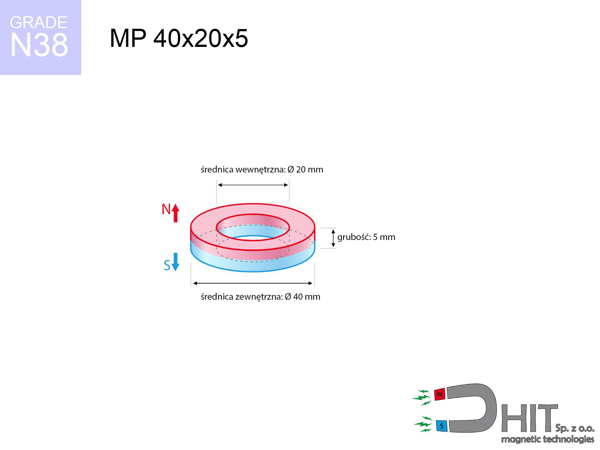
MP 40x20x5 / N38 - ring magnet
ring magnet
Catalog no 030199
GTIN/EAN: 5906301812166
Diameter
40 mm [±0,1 mm]
internal diameter Ø
20 mm [±0,1 mm]
Height
5 mm [±0,1 mm]
Weight
35.34 g
Magnetization Direction
↑ axial
Load capacity
7.24 kg / 70.98 N
Magnetic Induction
150.36 mT / 1504 Gs
Coating
[NiCuNi] Nickel
12.24 ZŁ with VAT / pcs + price for transport
9.95 ZŁ net + 23% VAT / pcs
bulk discounts:
Need more?Engineering report for this magnet
Full PDF analysis: pull and shear force, effect of distance, temperature and plate thickness, safety distances and the demagnetization curve.
Contact us by phone
+48 22 499 98 98
otherwise get in touch by means of
inquiry form
the contact section.
Weight along with form of magnetic components can be calculated on our
magnetic calculator.
Same-day processing for orders placed before 14:00.
Detailed specification - MP 40x20x5 / N38 - ring magnet
Specification / characteristics - MP 40x20x5 / N38 - ring magnet
| properties | values |
|---|---|
| Cat. no. | 030199 |
| GTIN/EAN | 5906301812166 |
| Production/Distribution | Dhit sp. z o.o. |
| Country of origin | Poland / China / Germany |
| Customs code | 85059029 |
| Diameter | 40 mm [±0,1 mm] |
| internal diameter Ø | 20 mm [±0,1 mm] |
| Height | 5 mm [±0,1 mm] |
| Weight | 35.34 g |
| Magnetization Direction | ↑ axial |
| Load capacity ~ ? | 7.24 kg / 70.98 N |
| Magnetic Induction ~ ? | 150.36 mT / 1504 Gs |
| Coating | [NiCuNi] Nickel |
| Manufacturing Tolerance | ±0.1 mm |
Magnetic properties of material N38
| properties | values | units |
|---|---|---|
| remenance Br [min. - max.] ? | 12.2-12.6 | kGs |
| remenance Br [min. - max.] ? | 1220-1260 | mT |
| coercivity bHc ? | 10.8-11.5 | kOe |
| coercivity bHc ? | 860-915 | kA/m |
| actual internal force iHc | ≥ 12 | kOe |
| actual internal force iHc | ≥ 955 | kA/m |
| energy density [min. - max.] ? | 36-38 | BH max MGOe |
| energy density [min. - max.] ? | 287-303 | BH max KJ/m |
| max. temperature ? | ≤ 80 | °C |
Physical properties of sintered neodymium magnets Nd2Fe14B at 20°C
| properties | values | units |
|---|---|---|
| Vickers hardness | ≥550 | Hv |
| Density | ≥7.4 | g/cm3 |
| Curie Temperature TC | 312 - 380 | °C |
| Curie Temperature TF | 593 - 716 | °F |
| Specific resistance | 150 | μΩ⋅cm |
| Bending strength | 250 | MPa |
| Compressive strength | 1000~1100 | MPa |
| Thermal expansion parallel (∥) to orientation (M) | (3-4) x 10-6 | °C-1 |
| Thermal expansion perpendicular (⊥) to orientation (M) | -(1-3) x 10-6 | °C-1 |
| Young's modulus | 1.7 x 10⁴ | kg/mm² |
Physical analysis of the product - data
The following data constitute the outcome of a engineering calculation. Results rely on algorithms for the class Nd2Fe14B. Real-world parameters might slightly differ. Treat these data as a reference point during assembly planning.
Table 1: Static pull force (pull vs gap) - interaction chart
MP 40x20x5 / N38
| Distance (mm) | Induction (Gauss) / mT | Pull Force (kg/lbs/g/N) | Risk Status |
|---|---|---|---|
| 0 mm |
5269 Gs
526.9 mT
|
7.24 kg / 15.96 pounds
7240.0 g / 71.0 N
|
medium risk |
| 1 mm |
5005 Gs
500.5 mT
|
6.53 kg / 14.41 pounds
6534.7 g / 64.1 N
|
medium risk |
| 2 mm |
4739 Gs
473.9 mT
|
5.86 kg / 12.91 pounds
5857.7 g / 57.5 N
|
medium risk |
| 3 mm |
4475 Gs
447.5 mT
|
5.22 kg / 11.51 pounds
5222.2 g / 51.2 N
|
medium risk |
| 5 mm |
3960 Gs
396.0 mT
|
4.09 kg / 9.02 pounds
4090.8 g / 40.1 N
|
medium risk |
| 10 mm |
2832 Gs
283.2 mT
|
2.09 kg / 4.61 pounds
2092.3 g / 20.5 N
|
medium risk |
| 15 mm |
1990 Gs
199.0 mT
|
1.03 kg / 2.28 pounds
1033.4 g / 10.1 N
|
low risk |
| 20 mm |
1407 Gs
140.7 mT
|
0.52 kg / 1.14 pounds
516.3 g / 5.1 N
|
low risk |
| 30 mm |
745 Gs
74.5 mT
|
0.14 kg / 0.32 pounds
144.6 g / 1.4 N
|
low risk |
| 50 mm |
268 Gs
26.8 mT
|
0.02 kg / 0.04 pounds
18.7 g / 0.2 N
|
low risk |
Table 2: Shear hold (vertical surface)
MP 40x20x5 / N38
| Distance (mm) | Friction coefficient | Pull Force (kg/lbs/g/N) |
|---|---|---|
| 0 mm | Stal (~0.2) |
1.45 kg / 3.19 pounds
1448.0 g / 14.2 N
|
| 1 mm | Stal (~0.2) |
1.31 kg / 2.88 pounds
1306.0 g / 12.8 N
|
| 2 mm | Stal (~0.2) |
1.17 kg / 2.58 pounds
1172.0 g / 11.5 N
|
| 3 mm | Stal (~0.2) |
1.04 kg / 2.30 pounds
1044.0 g / 10.2 N
|
| 5 mm | Stal (~0.2) |
0.82 kg / 1.80 pounds
818.0 g / 8.0 N
|
| 10 mm | Stal (~0.2) |
0.42 kg / 0.92 pounds
418.0 g / 4.1 N
|
| 15 mm | Stal (~0.2) |
0.21 kg / 0.45 pounds
206.0 g / 2.0 N
|
| 20 mm | Stal (~0.2) |
0.10 kg / 0.23 pounds
104.0 g / 1.0 N
|
| 30 mm | Stal (~0.2) |
0.03 kg / 0.06 pounds
28.0 g / 0.3 N
|
| 50 mm | Stal (~0.2) |
0.00 kg / 0.01 pounds
4.0 g / 0.0 N
|
Table 3: Vertical assembly (sliding) - behavior on slippery surfaces
MP 40x20x5 / N38
| Surface type | Friction coefficient / % Mocy | Max load (kg/lbs/g/N) |
|---|---|---|
| Raw steel |
µ = 0.3
30% Nominalnej Siły
|
2.17 kg / 4.79 pounds
2172.0 g / 21.3 N
|
| Painted steel (standard) |
µ = 0.2
20% Nominalnej Siły
|
1.45 kg / 3.19 pounds
1448.0 g / 14.2 N
|
| Oily/slippery steel |
µ = 0.1
10% Nominalnej Siły
|
0.72 kg / 1.60 pounds
724.0 g / 7.1 N
|
| Magnet with anti-slip rubber |
µ = 0.5
50% Nominalnej Siły
|
3.62 kg / 7.98 pounds
3620.0 g / 35.5 N
|
Table 4: Material efficiency (substrate influence) - sheet metal selection
MP 40x20x5 / N38
| Steel thickness (mm) | % power | Real pull force (kg/lbs/g/N) |
|---|---|---|
| 0.5 mm |
|
0.72 kg / 1.60 pounds
724.0 g / 7.1 N
|
| 1 mm |
|
1.81 kg / 3.99 pounds
1810.0 g / 17.8 N
|
| 2 mm |
|
3.62 kg / 7.98 pounds
3620.0 g / 35.5 N
|
| 3 mm |
|
5.43 kg / 11.97 pounds
5430.0 g / 53.3 N
|
| 5 mm |
|
7.24 kg / 15.96 pounds
7240.0 g / 71.0 N
|
| 10 mm |
|
7.24 kg / 15.96 pounds
7240.0 g / 71.0 N
|
| 11 mm |
|
7.24 kg / 15.96 pounds
7240.0 g / 71.0 N
|
| 12 mm |
|
7.24 kg / 15.96 pounds
7240.0 g / 71.0 N
|
Table 5: Thermal resistance (stability) - thermal limit
MP 40x20x5 / N38
| Ambient temp. (°C) | Power loss | Remaining pull (kg/lbs/g/N) | Status |
|---|---|---|---|
| 20 °C | 0.0% |
7.24 kg / 15.96 pounds
7240.0 g / 71.0 N
|
OK |
| 40 °C | -2.2% |
7.08 kg / 15.61 pounds
7080.7 g / 69.5 N
|
OK |
| 60 °C | -4.4% |
6.92 kg / 15.26 pounds
6921.4 g / 67.9 N
|
OK |
| 80 °C | -6.6% |
6.76 kg / 14.91 pounds
6762.2 g / 66.3 N
|
|
| 100 °C | -28.8% |
5.15 kg / 11.36 pounds
5154.9 g / 50.6 N
|
Table 6: Magnet-Magnet interaction (repulsion) - field collision
MP 40x20x5 / N38
| Gap (mm) | Attraction (kg/lbs) (N-S) | Lateral Force (kg/lbs/g/N) | Repulsion (kg/lbs) (N-N) |
|---|---|---|---|
| 0 mm |
179.94 kg / 396.69 pounds
5 920 Gs
|
26.99 kg / 59.50 pounds
26991 g / 264.8 N
|
N/A |
| 1 mm |
171.16 kg / 377.35 pounds
10 277 Gs
|
25.67 kg / 56.60 pounds
25675 g / 251.9 N
|
154.05 kg / 339.62 pounds
~0 Gs
|
| 2 mm |
162.41 kg / 358.05 pounds
10 011 Gs
|
24.36 kg / 53.71 pounds
24361 g / 239.0 N
|
146.17 kg / 322.24 pounds
~0 Gs
|
| 3 mm |
153.87 kg / 339.24 pounds
9 744 Gs
|
23.08 kg / 50.89 pounds
23081 g / 226.4 N
|
138.49 kg / 305.31 pounds
~0 Gs
|
| 5 mm |
137.55 kg / 303.25 pounds
9 213 Gs
|
20.63 kg / 45.49 pounds
20633 g / 202.4 N
|
123.80 kg / 272.92 pounds
~0 Gs
|
| 10 mm |
101.67 kg / 224.14 pounds
7 921 Gs
|
15.25 kg / 33.62 pounds
15251 g / 149.6 N
|
91.50 kg / 201.73 pounds
~0 Gs
|
| 20 mm |
52.00 kg / 114.64 pounds
5 665 Gs
|
7.80 kg / 17.20 pounds
7800 g / 76.5 N
|
46.80 kg / 103.18 pounds
~0 Gs
|
| 50 mm |
6.64 kg / 14.64 pounds
2 025 Gs
|
1.00 kg / 2.20 pounds
996 g / 9.8 N
|
5.98 kg / 13.18 pounds
~0 Gs
|
| 60 mm |
3.59 kg / 7.92 pounds
1 489 Gs
|
0.54 kg / 1.19 pounds
539 g / 5.3 N
|
3.23 kg / 7.13 pounds
~0 Gs
|
| 70 mm |
2.03 kg / 4.48 pounds
1 120 Gs
|
0.30 kg / 0.67 pounds
305 g / 3.0 N
|
1.83 kg / 4.03 pounds
~0 Gs
|
| 80 mm |
1.20 kg / 2.64 pounds
860 Gs
|
0.18 kg / 0.40 pounds
180 g / 1.8 N
|
1.08 kg / 2.38 pounds
~0 Gs
|
| 90 mm |
0.73 kg / 1.62 pounds
673 Gs
|
0.11 kg / 0.24 pounds
110 g / 1.1 N
|
0.66 kg / 1.46 pounds
~0 Gs
|
| 100 mm |
0.47 kg / 1.03 pounds
536 Gs
|
0.07 kg / 0.15 pounds
70 g / 0.7 N
|
0.42 kg / 0.92 pounds
~0 Gs
|
Table 7: Safety (HSE) (implants) - warnings
MP 40x20x5 / N38
| Object / Device | Limit (Gauss) / mT | Safe distance |
|---|---|---|
| Pacemaker | 5 Gs (0.5 mT) | 24.0 cm |
| Hearing aid | 10 Gs (1.0 mT) | 18.5 cm |
| Timepiece | 20 Gs (2.0 mT) | 14.5 cm |
| Mobile device | 40 Gs (4.0 mT) | 11.0 cm |
| Remote | 50 Gs (5.0 mT) | 10.5 cm |
| Payment card | 400 Gs (40.0 mT) | 4.5 cm |
| HDD hard drive | 600 Gs (60.0 mT) | 3.5 cm |
Table 8: Collisions (kinetic energy) - warning
MP 40x20x5 / N38
| Start from (mm) | Speed (km/h) | Energy (J) | Predicted outcome |
|---|---|---|---|
| 10 mm |
16.84 km/h
(4.68 m/s)
|
0.39 J | |
| 30 mm |
25.31 km/h
(7.03 m/s)
|
0.87 J | |
| 50 mm |
32.33 km/h
(8.98 m/s)
|
1.43 J | |
| 100 mm |
45.65 km/h
(12.68 m/s)
|
2.84 J |
Table 9: Anti-corrosion coating durability
MP 40x20x5 / N38
| Technical parameter | Value / Description |
|---|---|
| Coating type | [NiCuNi] Nickel |
| Layer structure | Nickel - Copper - Nickel |
| Layer thickness | 10-20 µm |
| Salt spray test (SST) ? | 24 h |
| Recommended environment | Indoors only (dry) |
Table 10: Electrical data (Flux)
MP 40x20x5 / N38
| Parameter | Value | SI Unit / Description |
|---|---|---|
| Magnetic Flux | 56 325 Mx | 563.3 µWb |
| Pc Coefficient | 0.80 | High (Stable) |
Table 11: Underwater work (magnet fishing)
MP 40x20x5 / N38
| Environment | Effective steel pull | Effect |
|---|---|---|
| Air (land) | 7.24 kg | Standard |
| Water (riverbed) |
8.29 kg
(+1.05 kg buoyancy gain)
|
+14.5% |
1. Shear force
*Note: On a vertical wall, the magnet retains merely approx. 20-30% of its nominal pull.
2. Steel thickness impact
*Thin metal sheet (e.g. 0.5mm PC case) severely weakens the holding force.
3. Temperature resistance
*For N38 grade, the max working temp is 80°C.
4. Demagnetization curve and operating point (B-H)
chart generated for the permeance coefficient Pc (Permeance Coefficient) = 0.80
The chart above illustrates the magnetic characteristics of the material within the second quadrant of the hysteresis loop. The solid red line represents the demagnetization curve (material potential), while the dashed blue line is the load line based on the magnet's geometry. The Pc (Permeance Coefficient), also known as the load line slope, is a dimensionless value that describes the relationship between the magnet's shape and its magnetic stability. The intersection of these two lines (the black dot) is the operating point — it determines the actual magnetic flux density generated by the magnet in this specific configuration. A higher Pc value means the magnet is more 'slender' (tall relative to its area), resulting in a higher operating point and better resistance to irreversible demagnetization caused by external fields or temperature. A value of 0.42 is relatively low (typical for flat magnets), meaning the operating point is closer to the 'knee' of the curve — caution is advised when operating at temperatures near the maximum limit to avoid strength loss.
Elemental analysis
| iron (Fe) | 64% – 68% |
| neodymium (Nd) | 29% – 32% |
| boron (B) | 1.1% – 1.2% |
| dysprosium (Dy) | 0.5% – 2.0% |
| coating (Ni-Cu-Ni) | < 0.05% |
Environmental data
| recyclability (EoL) | 100% |
| recycled raw materials | ~10% (pre-cons) |
| carbon footprint | low / zredukowany |
| waste code (EWC) | 16 02 16 |
Other products

![SM 32x300 [2xM8] / N42 - magnetic separator](https://cdn3.dhit.pl/graphics/products/sm-32x300-2xm8-pel.jpg "SM 32x300 [2xM8] / N42 - magnetic separator")

![SM 32x225 [2xM8] / N42 - magnetic separator](https://cdn3.dhit.pl/graphics/products/sm-32x225-2xm8-dob.jpg "SM 32x225 [2xM8] / N42 - magnetic separator")
Advantages as well as disadvantages of Nd2Fe14B magnets.
Benefits
- Their power is maintained, and after approximately ten years it drops only by ~1% (theoretically),
- Magnets very well resist against demagnetization caused by ambient magnetic noise,
- By covering with a lustrous coating of gold, the element has an elegant look,
- They feature high magnetic induction at the operating surface, which improves attraction properties,
- Due to their durability and thermal resistance, neodymium magnets are capable of operate (depending on the shape) even at high temperatures reaching 230°C or more...
- Due to the potential of precise forming and customization to custom needs, magnetic components can be created in a broad palette of geometric configurations, which makes them more universal,
- Huge importance in future technologies – they serve a role in magnetic memories, drive modules, medical equipment, as well as modern systems.
- Thanks to concentrated force, small magnets offer high operating force, with minimal size,
Cons
- To avoid cracks upon strong impacts, we recommend using special steel holders. Such a solution protects the magnet and simultaneously improves its durability.
- We warn that neodymium magnets can lose their power at high temperatures. To prevent this, we advise our specialized [AH] magnets, which work effectively even at 230°C.
- Due to the susceptibility of magnets to corrosion in a humid environment, we suggest using waterproof magnets made of rubber, plastic or other material immune to moisture, when using outdoors
- Due to limitations in creating nuts and complex forms in magnets, we recommend using a housing - magnetic mount.
- Potential hazard resulting from small fragments of magnets are risky, if swallowed, which becomes key in the aspect of protecting the youngest. Furthermore, tiny parts of these products are able to complicate diagnosis medical in case of swallowing.
- High unit price – neodymium magnets have a higher price than other types of magnets (e.g. ferrite), which can limit application in large quantities
Pull force analysis
Optimal lifting capacity of a neodymium magnet – what it depends on?
- using a sheet made of high-permeability steel, functioning as a ideal flux conductor
- possessing a thickness of at least 10 mm to ensure full flux closure
- characterized by even structure
- with total lack of distance (no coatings)
- for force acting at a right angle (in the magnet axis)
- in neutral thermal conditions
Lifting capacity in real conditions – factors
- Space between surfaces – even a fraction of a millimeter of separation (caused e.g. by veneer or dirt) diminishes the pulling force, often by half at just 0.5 mm.
- Loading method – declared lifting capacity refers to pulling vertically. When applying parallel force, the magnet exhibits significantly lower power (typically approx. 20-30% of maximum force).
- Steel thickness – too thin plate does not close the flux, causing part of the power to be escaped to the other side.
- Metal type – different alloys reacts the same. Alloy additives weaken the attraction effect.
- Surface structure – the smoother and more polished the surface, the better the adhesion and higher the lifting capacity. Roughness acts like micro-gaps.
- Temperature influence – high temperature reduces magnetic field. Exceeding the limit temperature can permanently damage the magnet.
Lifting capacity testing was conducted on a smooth plate of suitable thickness, under a perpendicular pulling force, in contrast under parallel forces the lifting capacity is smaller. Additionally, even a minimal clearance between the magnet and the plate decreases the lifting capacity.
Warnings
Impact on smartphones
GPS units and mobile phones are extremely susceptible to magnetic fields. Close proximity with a powerful NdFeB magnet can decalibrate the internal compass in your phone.
Danger to pacemakers
Patients with a heart stimulator should maintain an safe separation from magnets. The magnetism can stop the operation of the implant.
Serious injuries
Risk of injury: The pulling power is so great that it can cause blood blisters, pinching, and broken bones. Protective gloves are recommended.
Heat warning
Do not overheat. NdFeB magnets are susceptible to heat. If you require operation above 80°C, inquire about special high-temperature series (H, SH, UH).
Dust is flammable
Powder created during cutting of magnets is self-igniting. Do not drill into magnets unless you are an expert.
Skin irritation risks
Medical facts indicate that nickel (the usual finish) is a strong allergen. If your skin reacts to metals, prevent touching magnets with bare hands and opt for coated magnets.
Adults only
Strictly keep magnets away from children. Ingestion danger is high, and the consequences of magnets clamping inside the body are tragic.
Beware of splinters
Neodymium magnets are sintered ceramics, meaning they are prone to chipping. Collision of two magnets leads to them breaking into small pieces.
Electronic devices
Do not bring magnets close to a wallet, laptop, or TV. The magnetic field can permanently damage these devices and wipe information from cards.
Handling rules
Use magnets consciously. Their immense force can shock even professionals. Be vigilant and respect their power.
Tabela kosztu i czasu dostawy
Płatność przed wysyłką:

GLS kurier
Przesyłka będzie u Ciebie za 2-3 dni
14.99 ZŁ

InPost Paczkomaty 24/7
Przesyłka będzie u Ciebie za 1-2 dni
12.30 ZŁ
Płatność przy odbiorze (pobranie):
GLS kurier
Przesyłka będzie u Ciebie za 1-2 dni
23.00 ZŁ
Rate the product
Your rating