

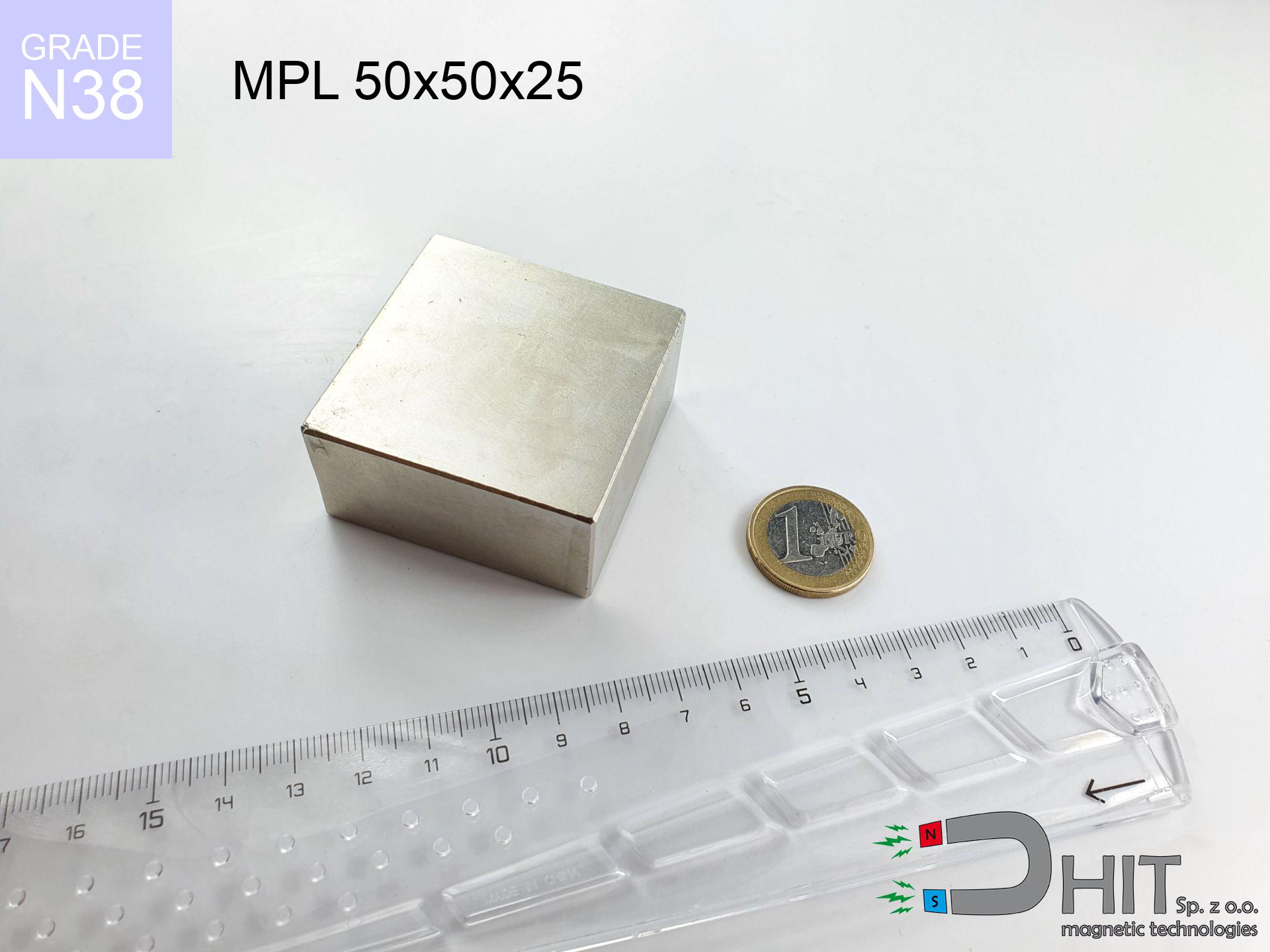
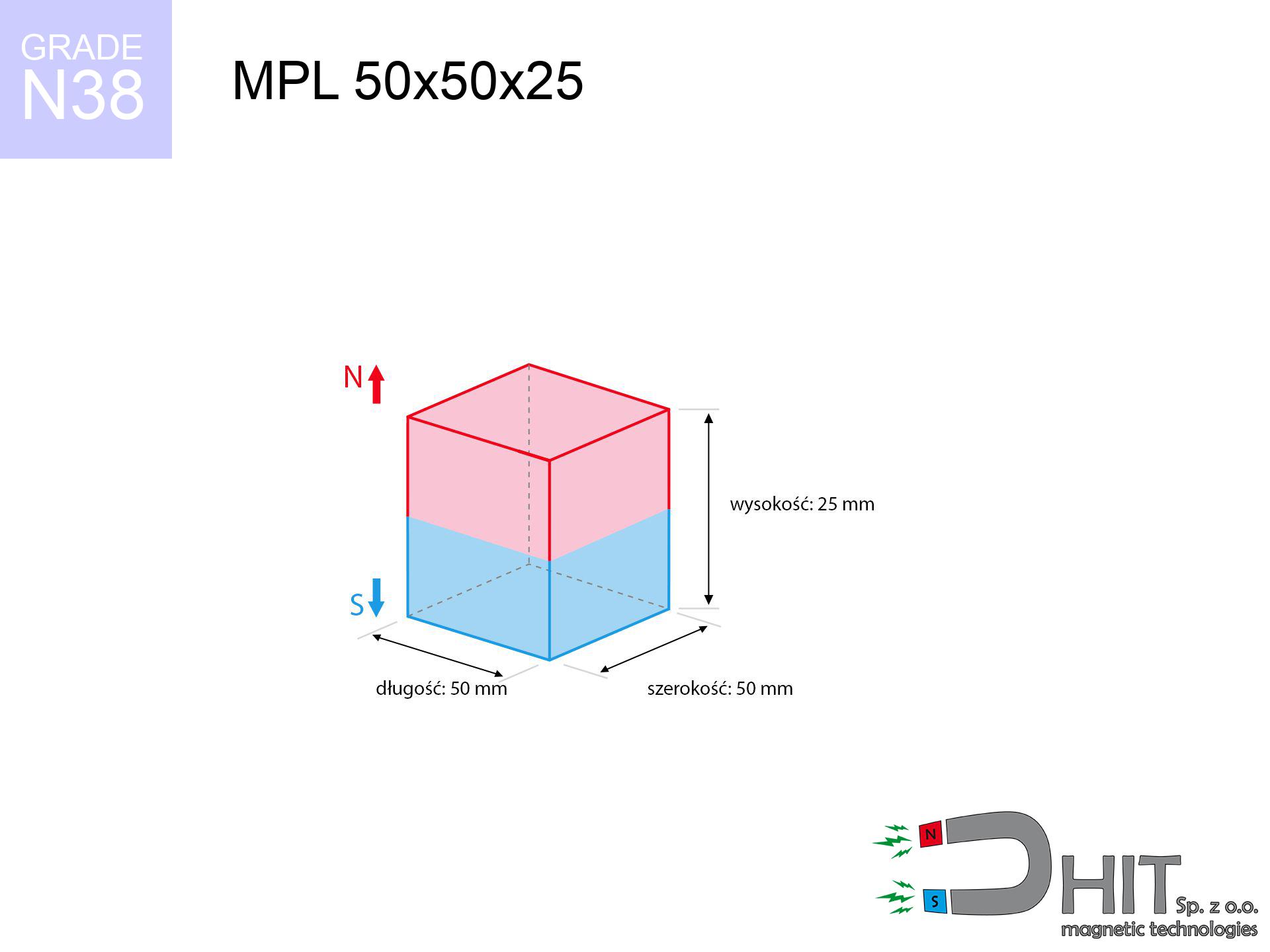
MPL 50x50x25 / N38 - lamellar magnet
lamellar magnet
Catalog no 020168
GTIN/EAN: 5906301811749
length
50 mm [±0,1 mm]
Width
50 mm [±0,1 mm]
Height
25 mm [±0,1 mm]
Weight
468.75 g
Magnetization Direction
↑ axial
Load capacity
90.53 kg / 888.15 N
Magnetic Induction
413.25 mT / 4133 Gs
Coating
[NiCuNi] Nickel
159.90 ZŁ with VAT / pcs + price for transport
130.00 ZŁ net + 23% VAT / pcs
bulk discounts:
Need more?
Call us now
+48 888 99 98 98
if you prefer drop us a message via
our online form
the contact section.
Weight as well as shape of a magnet can be checked on our
power calculator.
Same-day shipping for orders placed before 14:00.
Physical properties - MPL 50x50x25 / N38 - lamellar magnet
Specification / characteristics - MPL 50x50x25 / N38 - lamellar magnet
| properties | values |
|---|---|
| Cat. no. | 020168 |
| GTIN/EAN | 5906301811749 |
| Production/Distribution | Dhit sp. z o.o. |
| Country of origin | Poland / China / Germany |
| Customs code | 85059029 |
| length | 50 mm [±0,1 mm] |
| Width | 50 mm [±0,1 mm] |
| Height | 25 mm [±0,1 mm] |
| Weight | 468.75 g |
| Magnetization Direction | ↑ axial |
| Load capacity ~ ? | 90.53 kg / 888.15 N |
| Magnetic Induction ~ ? | 413.25 mT / 4133 Gs |
| Coating | [NiCuNi] Nickel |
| Manufacturing Tolerance | ±0.1 mm |
Magnetic properties of material N38
| properties | values | units |
|---|---|---|
| remenance Br [min. - max.] ? | 12.2-12.6 | kGs |
| remenance Br [min. - max.] ? | 1220-1260 | mT |
| coercivity bHc ? | 10.8-11.5 | kOe |
| coercivity bHc ? | 860-915 | kA/m |
| actual internal force iHc | ≥ 12 | kOe |
| actual internal force iHc | ≥ 955 | kA/m |
| energy density [min. - max.] ? | 36-38 | BH max MGOe |
| energy density [min. - max.] ? | 287-303 | BH max KJ/m |
| max. temperature ? | ≤ 80 | °C |
Physical properties of sintered neodymium magnets Nd2Fe14B at 20°C
| properties | values | units |
|---|---|---|
| Vickers hardness | ≥550 | Hv |
| Density | ≥7.4 | g/cm3 |
| Curie Temperature TC | 312 - 380 | °C |
| Curie Temperature TF | 593 - 716 | °F |
| Specific resistance | 150 | μΩ⋅cm |
| Bending strength | 250 | MPa |
| Compressive strength | 1000~1100 | MPa |
| Thermal expansion parallel (∥) to orientation (M) | (3-4) x 10-6 | °C-1 |
| Thermal expansion perpendicular (⊥) to orientation (M) | -(1-3) x 10-6 | °C-1 |
| Young's modulus | 1.7 x 10⁴ | kg/mm² |
Technical simulation of the product - data
The following values constitute the result of a mathematical simulation. Results rely on algorithms for the material Nd2Fe14B. Actual conditions might slightly differ. Use these calculations as a reference point when designing systems.
Table 1: Static pull force (pull vs distance) - power drop
MPL 50x50x25 / N38
| Distance (mm) | Induction (Gauss) / mT | Pull Force (kg/lbs/g/N) | Risk Status |
|---|---|---|---|
| 0 mm |
4132 Gs
413.2 mT
|
90.53 kg / 199.58 lbs
90530.0 g / 888.1 N
|
dangerous! |
| 1 mm |
3999 Gs
399.9 mT
|
84.79 kg / 186.94 lbs
84794.0 g / 831.8 N
|
dangerous! |
| 2 mm |
3861 Gs
386.1 mT
|
79.04 kg / 174.25 lbs
79038.6 g / 775.4 N
|
dangerous! |
| 3 mm |
3720 Gs
372.0 mT
|
73.38 kg / 161.78 lbs
73381.8 g / 719.9 N
|
dangerous! |
| 5 mm |
3435 Gs
343.5 mT
|
62.56 kg / 137.93 lbs
62564.2 g / 613.8 N
|
dangerous! |
| 10 mm |
2742 Gs
274.2 mT
|
39.87 kg / 87.90 lbs
39868.7 g / 391.1 N
|
dangerous! |
| 15 mm |
2137 Gs
213.7 mT
|
24.21 kg / 53.37 lbs
24210.4 g / 237.5 N
|
dangerous! |
| 20 mm |
1649 Gs
164.9 mT
|
14.41 kg / 31.77 lbs
14409.9 g / 141.4 N
|
dangerous! |
| 30 mm |
988 Gs
98.8 mT
|
5.17 kg / 11.40 lbs
5170.9 g / 50.7 N
|
warning |
| 50 mm |
399 Gs
39.9 mT
|
0.85 kg / 1.86 lbs
845.8 g / 8.3 N
|
weak grip |
Table 2: Vertical capacity (vertical surface)
MPL 50x50x25 / N38
| Distance (mm) | Friction coefficient | Pull Force (kg/lbs/g/N) |
|---|---|---|
| 0 mm | Stal (~0.2) |
18.11 kg / 39.92 lbs
18106.0 g / 177.6 N
|
| 1 mm | Stal (~0.2) |
16.96 kg / 37.39 lbs
16958.0 g / 166.4 N
|
| 2 mm | Stal (~0.2) |
15.81 kg / 34.85 lbs
15808.0 g / 155.1 N
|
| 3 mm | Stal (~0.2) |
14.68 kg / 32.36 lbs
14676.0 g / 144.0 N
|
| 5 mm | Stal (~0.2) |
12.51 kg / 27.58 lbs
12512.0 g / 122.7 N
|
| 10 mm | Stal (~0.2) |
7.97 kg / 17.58 lbs
7974.0 g / 78.2 N
|
| 15 mm | Stal (~0.2) |
4.84 kg / 10.67 lbs
4842.0 g / 47.5 N
|
| 20 mm | Stal (~0.2) |
2.88 kg / 6.35 lbs
2882.0 g / 28.3 N
|
| 30 mm | Stal (~0.2) |
1.03 kg / 2.28 lbs
1034.0 g / 10.1 N
|
| 50 mm | Stal (~0.2) |
0.17 kg / 0.37 lbs
170.0 g / 1.7 N
|
Table 3: Vertical assembly (sliding) - behavior on slippery surfaces
MPL 50x50x25 / N38
| Surface type | Friction coefficient / % Mocy | Max load (kg/lbs/g/N) |
|---|---|---|
| Raw steel |
µ = 0.3
30% Nominalnej Siły
|
27.16 kg / 59.88 lbs
27159.0 g / 266.4 N
|
| Painted steel (standard) |
µ = 0.2
20% Nominalnej Siły
|
18.11 kg / 39.92 lbs
18106.0 g / 177.6 N
|
| Oily/slippery steel |
µ = 0.1
10% Nominalnej Siły
|
9.05 kg / 19.96 lbs
9053.0 g / 88.8 N
|
| Magnet with anti-slip rubber |
µ = 0.5
50% Nominalnej Siły
|
45.27 kg / 99.79 lbs
45265.0 g / 444.0 N
|
Table 4: Steel thickness (saturation) - power losses
MPL 50x50x25 / N38
| Steel thickness (mm) | % power | Real pull force (kg/lbs/g/N) |
|---|---|---|
| 0.5 mm |
|
3.02 kg / 6.65 lbs
3017.7 g / 29.6 N
|
| 1 mm |
|
7.54 kg / 16.63 lbs
7544.2 g / 74.0 N
|
| 2 mm |
|
15.09 kg / 33.26 lbs
15088.3 g / 148.0 N
|
| 3 mm |
|
22.63 kg / 49.90 lbs
22632.5 g / 222.0 N
|
| 5 mm |
|
37.72 kg / 83.16 lbs
37720.8 g / 370.0 N
|
| 10 mm |
|
75.44 kg / 166.32 lbs
75441.7 g / 740.1 N
|
| 11 mm |
|
82.99 kg / 182.95 lbs
82985.8 g / 814.1 N
|
| 12 mm |
|
90.53 kg / 199.58 lbs
90530.0 g / 888.1 N
|
Table 5: Working in heat (material behavior) - thermal limit
MPL 50x50x25 / N38
| Ambient temp. (°C) | Power loss | Remaining pull (kg/lbs/g/N) | Status |
|---|---|---|---|
| 20 °C | 0.0% |
90.53 kg / 199.58 lbs
90530.0 g / 888.1 N
|
OK |
| 40 °C | -2.2% |
88.54 kg / 195.19 lbs
88538.3 g / 868.6 N
|
OK |
| 60 °C | -4.4% |
86.55 kg / 190.80 lbs
86546.7 g / 849.0 N
|
|
| 80 °C | -6.6% |
84.56 kg / 186.41 lbs
84555.0 g / 829.5 N
|
|
| 100 °C | -28.8% |
64.46 kg / 142.10 lbs
64457.4 g / 632.3 N
|
Table 6: Magnet-Magnet interaction (repulsion) - field range
MPL 50x50x25 / N38
| Gap (mm) | Attraction (kg/lbs) (N-S) | Shear Strength (kg/lbs/g/N) | Repulsion (kg/lbs) (N-N) |
|---|---|---|---|
| 0 mm |
263.15 kg / 580.14 lbs
5 403 Gs
|
39.47 kg / 87.02 lbs
39472 g / 387.2 N
|
N/A |
| 1 mm |
254.89 kg / 561.94 lbs
8 133 Gs
|
38.23 kg / 84.29 lbs
38234 g / 375.1 N
|
229.40 kg / 505.75 lbs
~0 Gs
|
| 2 mm |
246.47 kg / 543.38 lbs
7 998 Gs
|
36.97 kg / 81.51 lbs
36971 g / 362.7 N
|
221.83 kg / 489.04 lbs
~0 Gs
|
| 3 mm |
238.08 kg / 524.88 lbs
7 861 Gs
|
35.71 kg / 78.73 lbs
35713 g / 350.3 N
|
214.28 kg / 472.40 lbs
~0 Gs
|
| 5 mm |
221.48 kg / 488.27 lbs
7 582 Gs
|
33.22 kg / 73.24 lbs
33222 g / 325.9 N
|
199.33 kg / 439.45 lbs
~0 Gs
|
| 10 mm |
181.86 kg / 400.93 lbs
6 870 Gs
|
27.28 kg / 60.14 lbs
27279 g / 267.6 N
|
163.67 kg / 360.83 lbs
~0 Gs
|
| 20 mm |
115.89 kg / 255.49 lbs
5 484 Gs
|
17.38 kg / 38.32 lbs
17383 g / 170.5 N
|
104.30 kg / 229.94 lbs
~0 Gs
|
| 50 mm |
24.93 kg / 54.97 lbs
2 544 Gs
|
3.74 kg / 8.25 lbs
3740 g / 36.7 N
|
22.44 kg / 49.47 lbs
~0 Gs
|
| 60 mm |
15.03 kg / 33.14 lbs
1 975 Gs
|
2.25 kg / 4.97 lbs
2255 g / 22.1 N
|
13.53 kg / 29.82 lbs
~0 Gs
|
| 70 mm |
9.24 kg / 20.37 lbs
1 548 Gs
|
1.39 kg / 3.05 lbs
1386 g / 13.6 N
|
8.31 kg / 18.33 lbs
~0 Gs
|
| 80 mm |
5.81 kg / 12.80 lbs
1 228 Gs
|
0.87 kg / 1.92 lbs
871 g / 8.5 N
|
5.23 kg / 11.52 lbs
~0 Gs
|
| 90 mm |
3.74 kg / 8.24 lbs
985 Gs
|
0.56 kg / 1.24 lbs
560 g / 5.5 N
|
3.36 kg / 7.41 lbs
~0 Gs
|
| 100 mm |
2.46 kg / 5.42 lbs
799 Gs
|
0.37 kg / 0.81 lbs
369 g / 3.6 N
|
2.21 kg / 4.88 lbs
~0 Gs
|
Table 7: Safety (HSE) (implants) - warnings
MPL 50x50x25 / N38
| Object / Device | Limit (Gauss) / mT | Safe distance |
|---|---|---|
| Pacemaker | 5 Gs (0.5 mT) | 28.0 cm |
| Hearing aid | 10 Gs (1.0 mT) | 22.0 cm |
| Timepiece | 20 Gs (2.0 mT) | 17.0 cm |
| Phone / Smartphone | 40 Gs (4.0 mT) | 13.5 cm |
| Car key | 50 Gs (5.0 mT) | 12.5 cm |
| Payment card | 400 Gs (40.0 mT) | 5.0 cm |
| HDD hard drive | 600 Gs (60.0 mT) | 4.5 cm |
Table 8: Dynamics (cracking risk) - collision effects
MPL 50x50x25 / N38
| Start from (mm) | Speed (km/h) | Energy (J) | Predicted outcome |
|---|---|---|---|
| 10 mm |
17.45 km/h
(4.85 m/s)
|
5.51 J | |
| 30 mm |
25.13 km/h
(6.98 m/s)
|
11.42 J | |
| 50 mm |
31.52 km/h
(8.76 m/s)
|
17.97 J | |
| 100 mm |
44.33 km/h
(12.31 m/s)
|
35.54 J |
Table 9: Anti-corrosion coating durability
MPL 50x50x25 / N38
| Technical parameter | Value / Description |
|---|---|
| Coating type | [NiCuNi] Nickel |
| Layer structure | Nickel - Copper - Nickel |
| Layer thickness | 10-20 µm |
| Salt spray test (SST) ? | 24 h |
| Recommended environment | Indoors only (dry) |
Table 10: Electrical data (Flux)
MPL 50x50x25 / N38
| Parameter | Value | SI Unit / Description |
|---|---|---|
| Magnetic Flux | 105 093 Mx | 1050.9 µWb |
| Pc Coefficient | 0.54 | Low (Flat) |
Table 11: Hydrostatics and buoyancy
MPL 50x50x25 / N38
| Environment | Effective steel pull | Effect |
|---|---|---|
| Air (land) | 90.53 kg | Standard |
| Water (riverbed) |
103.66 kg
(+13.13 kg buoyancy gain)
|
+14.5% |
1. Vertical hold
*Caution: On a vertical wall, the magnet holds only approx. 20-30% of its perpendicular strength.
2. Efficiency vs thickness
*Thin metal sheet (e.g. computer case) significantly weakens the holding force.
3. Heat tolerance
*For N38 material, the safety limit is 80°C.
4. Demagnetization curve and operating point (B-H)
chart generated for the permeance coefficient Pc (Permeance Coefficient) = 0.54
This simulation demonstrates the magnetic stability of the selected magnet under specific geometric conditions. The solid red line represents the demagnetization curve (material potential), while the dashed blue line is the load line based on the magnet's geometry. The Pc (Permeance Coefficient), also known as the load line slope, is a dimensionless value that describes the relationship between the magnet's shape and its magnetic stability. The intersection of these two lines (the black dot) is the operating point — it determines the actual magnetic flux density generated by the magnet in this specific configuration. A higher Pc value means the magnet is more 'slender' (tall relative to its area), resulting in a higher operating point and better resistance to irreversible demagnetization caused by external fields or temperature. A value of 0.42 is relatively low (typical for flat magnets), meaning the operating point is closer to the 'knee' of the curve — caution is advised when operating at temperatures near the maximum limit to avoid strength loss.
Material specification
| iron (Fe) | 64% – 68% |
| neodymium (Nd) | 29% – 32% |
| boron (B) | 1.1% – 1.2% |
| dysprosium (Dy) | 0.5% – 2.0% |
| coating (Ni-Cu-Ni) | < 0.05% |
Environmental data
| recyclability (EoL) | 100% |
| recycled raw materials | ~10% (pre-cons) |
| carbon footprint | low / zredukowany |
| waste code (EWC) | 16 02 16 |
See also deals
![SM 32x175 [2xM8] / N42 - magnetic separator](https://cdn3.dhit.pl/graphics/products/sm-32x175-2xm8-tej.jpg "SM 32x175 [2xM8] / N42 - magnetic separator")
![UMGW 20x15x7 [M4] GW / N38 - magnetic holder internal thread](https://cdn3.dhit.pl/graphics/products/um-20x15x7-m4-gw-big.jpg "UMGW 20x15x7 [M4] GW / N38 - magnetic holder internal thread")
![UMGGW 43x6 [M4] GW / N38 - magnetic holder rubber internal thread](https://cdn3.dhit.pl/graphics/products/umg-43x6-m6-gw-hel.jpg "UMGGW 43x6 [M4] GW / N38 - magnetic holder rubber internal thread")

Pros as well as cons of neodymium magnets.
Advantages
- They virtually do not lose power, because even after ten years the decline in efficiency is only ~1% (according to literature),
- Magnets perfectly protect themselves against demagnetization caused by ambient magnetic noise,
- The use of an metallic coating of noble metals (nickel, gold, silver) causes the element to present itself better,
- The surface of neodymium magnets generates a unique magnetic field – this is a distinguishing feature,
- Through (appropriate) combination of ingredients, they can achieve high thermal resistance, allowing for action at temperatures reaching 230°C and above...
- Thanks to modularity in constructing and the capacity to adapt to complex applications,
- Fundamental importance in modern industrial fields – they are used in HDD drives, brushless drives, precision medical tools, and industrial machines.
- Thanks to concentrated force, small magnets offer high operating force, in miniature format,
Cons
- At strong impacts they can break, therefore we advise placing them in strong housings. A metal housing provides additional protection against damage and increases the magnet's durability.
- When exposed to high temperature, neodymium magnets suffer a drop in power. Often, when the temperature exceeds 80°C, their strength decreases (depending on the size, as well as shape of the magnet). For those who need magnets for extreme conditions, we offer [AH] versions withstanding up to 230°C
- They rust in a humid environment - during use outdoors we recommend using waterproof magnets e.g. in rubber, plastic
- Due to limitations in realizing nuts and complicated forms in magnets, we recommend using cover - magnetic holder.
- Possible danger resulting from small fragments of magnets are risky, when accidentally swallowed, which is particularly important in the context of child health protection. Additionally, small components of these products can complicate diagnosis medical when they are in the body.
- Higher cost of purchase is a significant factor to consider compared to ceramic magnets, especially in budget applications
Lifting parameters
Maximum lifting capacity of the magnet – what contributes to it?
- using a base made of high-permeability steel, functioning as a magnetic yoke
- with a cross-section of at least 10 mm
- with an ideally smooth touching surface
- under conditions of ideal adhesion (metal-to-metal)
- under axial force vector (90-degree angle)
- at ambient temperature approx. 20 degrees Celsius
Magnet lifting force in use – key factors
- Gap between surfaces – even a fraction of a millimeter of distance (caused e.g. by veneer or dirt) drastically reduces the magnet efficiency, often by half at just 0.5 mm.
- Force direction – remember that the magnet holds strongest perpendicularly. Under shear forces, the capacity drops significantly, often to levels of 20-30% of the maximum value.
- Element thickness – for full efficiency, the steel must be sufficiently thick. Paper-thin metal restricts the lifting capacity (the magnet "punches through" it).
- Steel grade – the best choice is pure iron steel. Cast iron may generate lower lifting capacity.
- Surface quality – the smoother and more polished the surface, the better the adhesion and higher the lifting capacity. Roughness creates an air distance.
- Temperature influence – high temperature reduces pulling force. Exceeding the limit temperature can permanently demagnetize the magnet.
Lifting capacity was assessed using a polished steel plate of suitable thickness (min. 20 mm), under vertically applied force, however under shearing force the lifting capacity is smaller. Moreover, even a slight gap between the magnet’s surface and the plate decreases the holding force.
Safety rules for work with NdFeB magnets
Do not drill into magnets
Powder created during grinding of magnets is flammable. Do not drill into magnets unless you are an expert.
Precision electronics
A strong magnetic field negatively affects the functioning of compasses in phones and GPS navigation. Keep magnets near a device to prevent damaging the sensors.
Do not overheat magnets
Monitor thermal conditions. Exposing the magnet to high heat will destroy its properties and pulling force.
ICD Warning
Life threat: Strong magnets can deactivate heart devices and defibrillators. Stay away if you have medical devices.
Cards and drives
Avoid bringing magnets close to a wallet, laptop, or screen. The magnetic field can permanently damage these devices and erase data from cards.
Danger to the youngest
Neodymium magnets are not toys. Eating multiple magnets can lead to them connecting inside the digestive tract, which constitutes a critical condition and necessitates urgent medical intervention.
Caution required
Before starting, check safety instructions. Uncontrolled attraction can break the magnet or injure your hand. Be predictive.
Eye protection
Despite the nickel coating, the material is delicate and cannot withstand shocks. Do not hit, as the magnet may shatter into hazardous fragments.
Warning for allergy sufferers
Allergy Notice: The nickel-copper-nickel coating consists of nickel. If skin irritation occurs, cease handling magnets and use protective gear.
Physical harm
Big blocks can crush fingers instantly. Under no circumstances place your hand between two strong magnets.
Tabela kosztu i czasu dostawy
Płatność przed wysyłką:

GLS kurier
Przesyłka będzie u Ciebie za 2-3 dni
14.99 ZŁ

InPost Paczkomaty 24/7
Przesyłka będzie u Ciebie za 1-2 dni
12.30 ZŁ
Płatność przy odbiorze (pobranie):
GLS kurier
Przesyłka będzie u Ciebie za 1-2 dni
23.00 ZŁ
Rate the product
Your rating