

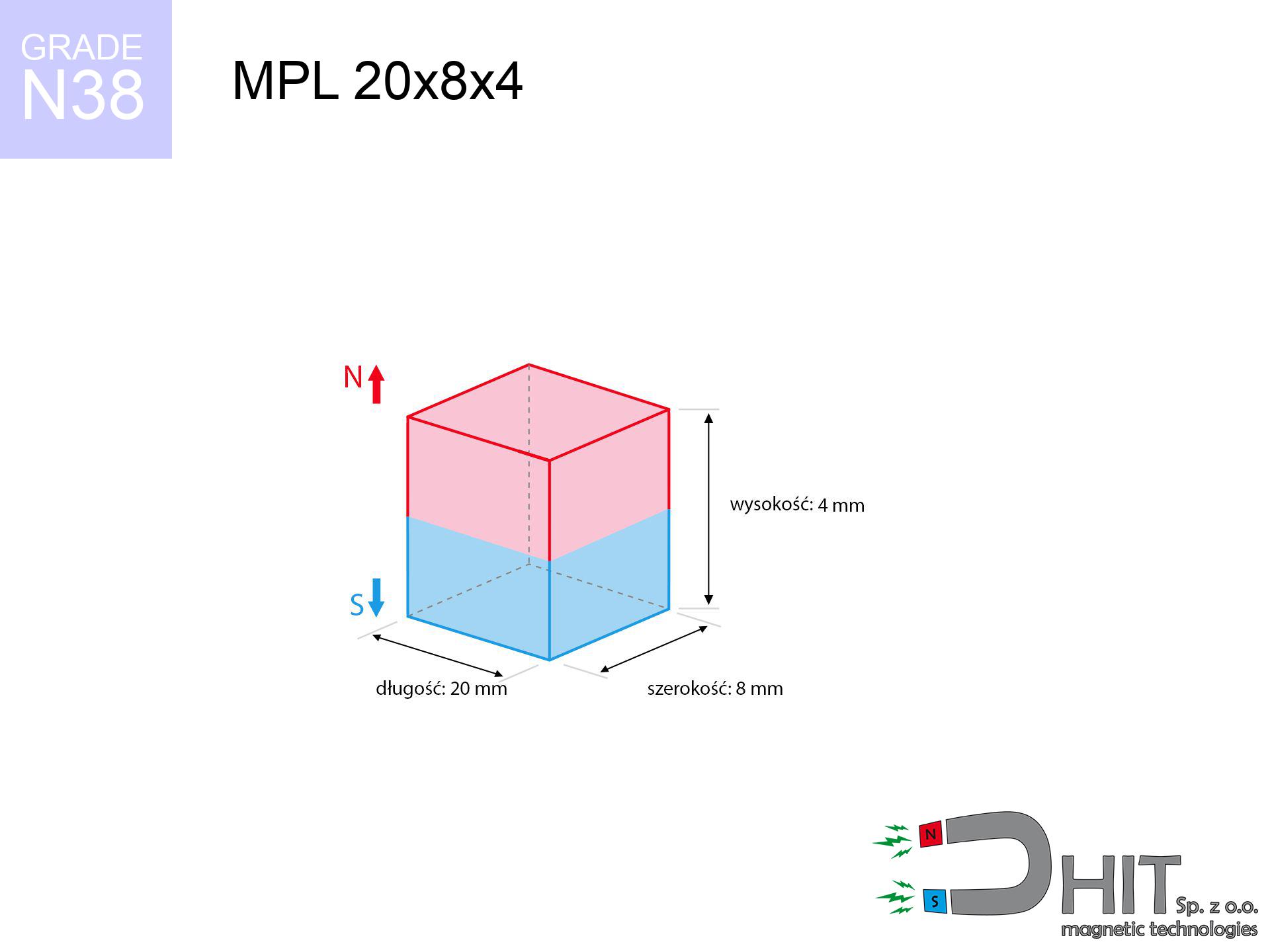
MPL 20x8x4 / N38 - lamellar magnet
lamellar magnet
Catalog no 020133
GTIN/EAN: 5906301811398
- length
- 20 mm [±0,1 mm]
- Width
- 8 mm [±0,1 mm]
- Height
- 4 mm [±0,1 mm]
- Weight
- 4.8 g
- Magnetization Direction
- ↑ axial
- Coating
- [NiCuNi] Nickel
3.67 zł with VAT / pcs + price for transport
2.98 zł net + 23% VAT / pcs
bulk discounts:
Need more?Engineering report for this magnet
Full PDF analysis: pull and shear force, effect of distance, temperature and plate thickness, safety distances and the demagnetization curve.
Call us now
+48 888 99 98 98
otherwise let us know by means of
form
the contact section.
Force and structure of magnets can be analyzed using our
magnetic mass calculator.
Orders placed before 14:00 will be shipped the same business day.
Product card - MPL 20x8x4 / N38 - lamellar magnet
Specification / characteristics - MPL 20x8x4 / N38 - lamellar magnet
| properties | values |
|---|---|
| Cat. no. | 020133 |
| GTIN/EAN | 5906301811398 |
| Production/Distribution | Dhit sp. z o.o. |
| Country of origin | Poland / China / Germany |
| Customs code | 85059029 |
| length | 20 mm [±0,1 mm] |
| Width | 8 mm [±0,1 mm] |
| Height | 4 mm [±0,1 mm] |
| Weight | 4.8 g |
| Magnetization Direction | ↑ axial |
| Load capacity ~ ? | 4.79 kg / 46.98 N |
| Magnetic Induction ~ ? | 336.99 mT / 3370 Gs |
| Coating | [NiCuNi] Nickel |
| Manufacturing Tolerance | ±0.1 mm |
Magnetic properties of material N38
| properties | values | units |
|---|---|---|
| remenance Br [min. - max.] ? | 12.2-12.6 | kGs |
| remenance Br [min. - max.] ? | 1220-1260 | mT |
| coercivity bHc ? | 10.8-11.5 | kOe |
| coercivity bHc ? | 860-915 | kA/m |
| actual internal force iHc | ≥ 12 | kOe |
| actual internal force iHc | ≥ 955 | kA/m |
| energy density [min. - max.] ? | 36-38 | BH max MGOe |
| energy density [min. - max.] ? | 287-303 | BH max KJ/m |
| max. temperature ? | ≤ 80 | °C |
Physical properties of sintered neodymium magnets Nd2Fe14B at 20°C
| properties | values | units |
|---|---|---|
| Vickers hardness | ≥550 | Hv |
| Density | ≥7.4 | g/cm3 |
| Curie Temperature TC | 312 - 380 | °C |
| Curie Temperature TF | 593 - 716 | °F |
| Specific resistance | 150 | μΩ⋅cm |
| Bending strength | 250 | MPa |
| Compressive strength | 1000~1100 | MPa |
| Thermal expansion parallel (∥) to orientation (M) | (3-4) x 10-6 | °C-1 |
| Thermal expansion perpendicular (⊥) to orientation (M) | -(1-3) x 10-6 | °C-1 |
| Young's modulus | 1.7 x 10⁴ | kg/mm² |
Technical analysis of the product - report
These information represent the outcome of a physical analysis. Results were calculated on algorithms for the material Nd2Fe14B. Operational performance may differ. Treat these calculations as a reference point for designers.
Table 1: Static pull force (pull vs distance) - power drop
MPL 20x8x4 / N38
| Distance (mm) | Induction (Gauss) / mT | Pull Force (kg/lbs/g/N) | Risk Status |
|---|---|---|---|
| 0 mm |
3368 Gs
336.8 mT
|
4.79 kg / 10.56 lbs
4790.0 g / 47.0 N
|
medium risk |
| 1 mm |
2818 Gs
281.8 mT
|
3.35 kg / 7.39 lbs
3352.3 g / 32.9 N
|
medium risk |
| 2 mm |
2266 Gs
226.6 mT
|
2.17 kg / 4.78 lbs
2167.6 g / 21.3 N
|
medium risk |
| 3 mm |
1794 Gs
179.4 mT
|
1.36 kg / 3.00 lbs
1358.6 g / 13.3 N
|
safe |
| 5 mm |
1130 Gs
113.0 mT
|
0.54 kg / 1.19 lbs
538.9 g / 5.3 N
|
safe |
| 10 mm |
416 Gs
41.6 mT
|
0.07 kg / 0.16 lbs
73.0 g / 0.7 N
|
safe |
| 15 mm |
187 Gs
18.7 mT
|
0.01 kg / 0.03 lbs
14.7 g / 0.1 N
|
safe |
| 20 mm |
97 Gs
9.7 mT
|
0.00 kg / 0.01 lbs
4.0 g / 0.0 N
|
safe |
| 30 mm |
35 Gs
3.5 mT
|
0.00 kg / 0.00 lbs
0.5 g / 0.0 N
|
safe |
| 50 mm |
9 Gs
0.9 mT
|
0.00 kg / 0.00 lbs
0.0 g / 0.0 N
|
safe |
Table 2: Shear hold (vertical surface)
MPL 20x8x4 / N38
| Distance (mm) | Friction coefficient | Pull Force (kg/lbs/g/N) |
|---|---|---|
| 0 mm | Stal (~0.2) |
0.96 kg / 2.11 lbs
958.0 g / 9.4 N
|
| 1 mm | Stal (~0.2) |
0.67 kg / 1.48 lbs
670.0 g / 6.6 N
|
| 2 mm | Stal (~0.2) |
0.43 kg / 0.96 lbs
434.0 g / 4.3 N
|
| 3 mm | Stal (~0.2) |
0.27 kg / 0.60 lbs
272.0 g / 2.7 N
|
| 5 mm | Stal (~0.2) |
0.11 kg / 0.24 lbs
108.0 g / 1.1 N
|
| 10 mm | Stal (~0.2) |
0.01 kg / 0.03 lbs
14.0 g / 0.1 N
|
| 15 mm | Stal (~0.2) |
0.00 kg / 0.00 lbs
2.0 g / 0.0 N
|
| 20 mm | Stal (~0.2) |
0.00 kg / 0.00 lbs
0.0 g / 0.0 N
|
| 30 mm | Stal (~0.2) |
0.00 kg / 0.00 lbs
0.0 g / 0.0 N
|
| 50 mm | Stal (~0.2) |
0.00 kg / 0.00 lbs
0.0 g / 0.0 N
|
Table 3: Wall mounting (shearing) - vertical pull
MPL 20x8x4 / N38
| Surface type | Friction coefficient / % Mocy | Max load (kg/lbs/g/N) |
|---|---|---|
| Raw steel |
µ = 0.3
30% Nominalnej Siły
|
1.44 kg / 3.17 lbs
1437.0 g / 14.1 N
|
| Painted steel (standard) |
µ = 0.2
20% Nominalnej Siły
|
0.96 kg / 2.11 lbs
958.0 g / 9.4 N
|
| Oily/slippery steel |
µ = 0.1
10% Nominalnej Siły
|
0.48 kg / 1.06 lbs
479.0 g / 4.7 N
|
| Magnet with anti-slip rubber |
µ = 0.5
50% Nominalnej Siły
|
2.40 kg / 5.28 lbs
2395.0 g / 23.5 N
|
Table 4: Steel thickness (saturation) - sheet metal selection
MPL 20x8x4 / N38
| Steel thickness (mm) | % power | Real pull force (kg/lbs/g/N) |
|---|---|---|
| 0.5 mm |
|
0.48 kg / 1.06 lbs
479.0 g / 4.7 N
|
| 1 mm |
|
1.20 kg / 2.64 lbs
1197.5 g / 11.7 N
|
| 2 mm |
|
2.40 kg / 5.28 lbs
2395.0 g / 23.5 N
|
| 3 mm |
|
3.59 kg / 7.92 lbs
3592.5 g / 35.2 N
|
| 5 mm |
|
4.79 kg / 10.56 lbs
4790.0 g / 47.0 N
|
| 10 mm |
|
4.79 kg / 10.56 lbs
4790.0 g / 47.0 N
|
| 11 mm |
|
4.79 kg / 10.56 lbs
4790.0 g / 47.0 N
|
| 12 mm |
|
4.79 kg / 10.56 lbs
4790.0 g / 47.0 N
|
Table 5: Working in heat (stability) - resistance threshold
MPL 20x8x4 / N38
| Ambient temp. (°C) | Power loss | Remaining pull (kg/lbs/g/N) | Status |
|---|---|---|---|
| 20 °C | 0.0% |
4.79 kg / 10.56 lbs
4790.0 g / 47.0 N
|
OK |
| 40 °C | -2.2% |
4.68 kg / 10.33 lbs
4684.6 g / 46.0 N
|
OK |
| 60 °C | -4.4% |
4.58 kg / 10.10 lbs
4579.2 g / 44.9 N
|
|
| 80 °C | -6.6% |
4.47 kg / 9.86 lbs
4473.9 g / 43.9 N
|
|
| 100 °C | -28.8% |
3.41 kg / 7.52 lbs
3410.5 g / 33.5 N
|
Table 6: Two magnets (attraction) - field collision
MPL 20x8x4 / N38
| Gap (mm) | Attraction (kg/lbs) (N-S) | Sliding Force (kg/lbs/g/N) | Repulsion (kg/lbs) (N-N) |
|---|---|---|---|
| 0 mm |
11.19 kg / 24.67 lbs
4 784 Gs
|
1.68 kg / 3.70 lbs
1678 g / 16.5 N
|
N/A |
| 1 mm |
9.49 kg / 20.93 lbs
6 205 Gs
|
1.42 kg / 3.14 lbs
1424 g / 14.0 N
|
8.54 kg / 18.84 lbs
~0 Gs
|
| 2 mm |
7.83 kg / 17.26 lbs
5 635 Gs
|
1.17 kg / 2.59 lbs
1175 g / 11.5 N
|
7.05 kg / 15.54 lbs
~0 Gs
|
| 3 mm |
6.34 kg / 13.97 lbs
5 069 Gs
|
0.95 kg / 2.10 lbs
951 g / 9.3 N
|
5.70 kg / 12.57 lbs
~0 Gs
|
| 5 mm |
4.02 kg / 8.85 lbs
4 035 Gs
|
0.60 kg / 1.33 lbs
602 g / 5.9 N
|
3.61 kg / 7.97 lbs
~0 Gs
|
| 10 mm |
1.26 kg / 2.78 lbs
2 259 Gs
|
0.19 kg / 0.42 lbs
189 g / 1.9 N
|
1.13 kg / 2.50 lbs
~0 Gs
|
| 20 mm |
0.17 kg / 0.38 lbs
832 Gs
|
0.03 kg / 0.06 lbs
26 g / 0.3 N
|
0.15 kg / 0.34 lbs
~0 Gs
|
| 50 mm |
0.00 kg / 0.01 lbs
112 Gs
|
0.00 kg / 0.00 lbs
0 g / 0.0 N
|
0.00 kg / 0.00 lbs
~0 Gs
|
| 60 mm |
0.00 kg / 0.00 lbs
70 Gs
|
0.00 kg / 0.00 lbs
0 g / 0.0 N
|
0.00 kg / 0.00 lbs
~0 Gs
|
| 70 mm |
0.00 kg / 0.00 lbs
46 Gs
|
0.00 kg / 0.00 lbs
0 g / 0.0 N
|
0.00 kg / 0.00 lbs
~0 Gs
|
| 80 mm |
0.00 kg / 0.00 lbs
32 Gs
|
0.00 kg / 0.00 lbs
0 g / 0.0 N
|
0.00 kg / 0.00 lbs
~0 Gs
|
| 90 mm |
0.00 kg / 0.00 lbs
23 Gs
|
0.00 kg / 0.00 lbs
0 g / 0.0 N
|
0.00 kg / 0.00 lbs
~0 Gs
|
| 100 mm |
0.00 kg / 0.00 lbs
17 Gs
|
0.00 kg / 0.00 lbs
0 g / 0.0 N
|
0.00 kg / 0.00 lbs
~0 Gs
|
Table 7: Hazards (electronics) - precautionary measures
MPL 20x8x4 / N38
| Object / Device | Limit (Gauss) / mT | Safe distance |
|---|---|---|
| Pacemaker | 5 Gs (0.5 mT) | 6.5 cm |
| Hearing aid | 10 Gs (1.0 mT) | 5.0 cm |
| Mechanical watch | 20 Gs (2.0 mT) | 4.0 cm |
| Phone / Smartphone | 40 Gs (4.0 mT) | 3.0 cm |
| Remote | 50 Gs (5.0 mT) | 3.0 cm |
| Payment card | 400 Gs (40.0 mT) | 1.5 cm |
| HDD hard drive | 600 Gs (60.0 mT) | 1.0 cm |
Table 8: Impact energy (cracking risk) - collision effects
MPL 20x8x4 / N38
| Start from (mm) | Speed (km/h) | Energy (J) | Predicted outcome |
|---|---|---|---|
| 10 mm |
24.61 km/h
(6.84 m/s)
|
0.11 J | |
| 30 mm |
24.86 km/h
(6.91 m/s)
|
0.11 J | |
| 50 mm |
24.86 km/h
(6.91 m/s)
|
0.11 J | |
| 100 mm |
24.87 km/h
(6.91 m/s)
|
0.11 J |
Table 9: Surface protection spec
MPL 20x8x4 / N38
| Technical parameter | Value / Description |
|---|---|
| Coating type | [NiCuNi] Nickel |
| Layer structure | Nickel - Copper - Nickel |
| Layer thickness | 10-20 µm |
| Salt spray test (SST) ? | 24 h |
| Recommended environment | Indoors only (dry) |
Table 10: Construction data (Flux)
MPL 20x8x4 / N38
| Parameter | Value | SI Unit / Description |
|---|---|---|
| Magnetic Flux | 5 277 Mx | 52.8 µWb |
| Pc Coefficient | 0.38 | Low (Flat) |
Table 11: Underwater work (magnet fishing)
MPL 20x8x4 / N38
| Environment | Effective steel pull | Effect |
|---|---|---|
| Air (land) | 4.79 kg | Standard |
| Water (riverbed) |
5.48 kg
(+0.69 kg buoyancy gain)
|
+14.5% |
1. Shear force
*Note: On a vertical surface, the magnet retains merely approx. 20-30% of its max power.
2. Steel thickness impact
*Thin steel (e.g. computer case) severely limits the holding force.
3. Heat tolerance
*For N38 material, the max working temp is 80°C.
4. Demagnetization curve and operating point (B-H)
chart generated for the permeance coefficient Pc (Permeance Coefficient) = 0.38
The chart above illustrates the magnetic characteristics of the material within the second quadrant of the hysteresis loop. The solid red line represents the demagnetization curve (material potential), while the dashed blue line is the load line based on the magnet's geometry. The Pc (Permeance Coefficient), also known as the load line slope, is a dimensionless value that describes the relationship between the magnet's shape and its magnetic stability. The intersection of these two lines (the black dot) is the operating point — it determines the actual magnetic flux density generated by the magnet in this specific configuration. A higher Pc value means the magnet is more 'slender' (tall relative to its area), resulting in a higher operating point and better resistance to irreversible demagnetization caused by external fields or temperature. A value of 0.42 is relatively low (typical for flat magnets), meaning the operating point is closer to the 'knee' of the curve — caution is advised when operating at temperatures near the maximum limit to avoid strength loss.
Elemental analysis
| iron (Fe) | 64% – 68% |
| neodymium (Nd) | 29% – 32% |
| boron (B) | 1.1% – 1.2% |
| dysprosium (Dy) | 0.5% – 2.0% |
| coating (Ni-Cu-Ni) | < 0.05% |
Sustainability
| recyclability (EoL) | 100% |
| recycled raw materials | ~10% (pre-cons) |
| carbon footprint | low / zredukowany |
| waste code (EWC) | 16 02 16 |
Other deals


Strengths as well as weaknesses of Nd2Fe14B magnets.
Pros
- They virtually do not lose power, because even after 10 years the decline in efficiency is only ~1% (in laboratory conditions),
- They feature excellent resistance to weakening of magnetic properties due to external fields,
- By applying a decorative coating of gold, the element acquires an proper look,
- The surface of neodymium magnets generates a maximum magnetic field – this is a distinguishing feature,
- Neodymium magnets are characterized by extremely high magnetic induction on the magnet surface and can function (depending on the form) even at a temperature of 230°C or more...
- Considering the ability of flexible molding and adaptation to individualized needs, magnetic components can be modeled in a variety of geometric configurations, which makes them more universal,
- Key role in future technologies – they are commonly used in hard drives, electric motors, medical devices, and other advanced devices.
- Compactness – despite small sizes they offer powerful magnetic field, making them ideal for precision applications
Cons
- Brittleness is one of their disadvantages. Upon strong impact they can break. We recommend keeping them in a strong case, which not only protects them against impacts but also raises their durability
- NdFeB magnets lose power when exposed to high temperatures. After reaching 80°C, many of them experience permanent weakening of power (a factor is the shape as well as dimensions of the magnet). We offer magnets specially adapted to work at temperatures up to 230°C marked [AH], which are extremely resistant to heat
- Magnets exposed to a humid environment can rust. Therefore when using outdoors, we recommend using waterproof magnets made of rubber, plastic or other material resistant to moisture
- We suggest a housing - magnetic mechanism, due to difficulties in realizing threads inside the magnet and complex shapes.
- Health risk to health – tiny shards of magnets are risky, when accidentally swallowed, which becomes key in the context of child safety. Additionally, small components of these devices are able to disrupt the diagnostic process medical in case of swallowing.
- High unit price – neodymium magnets have a higher price than other types of magnets (e.g. ferrite), which can limit application in large quantities
Lifting parameters
Maximum magnetic pulling force – what affects it?
- with the application of a sheet made of low-carbon steel, guaranteeing maximum field concentration
- whose thickness reaches at least 10 mm
- with a plane free of scratches
- under conditions of no distance (surface-to-surface)
- during pulling in a direction perpendicular to the plane
- in temp. approx. 20°C
Practical aspects of lifting capacity – factors
- Space between magnet and steel – even a fraction of a millimeter of distance (caused e.g. by veneer or dirt) diminishes the magnet efficiency, often by half at just 0.5 mm.
- Load vector – maximum parameter is obtained only during perpendicular pulling. The shear force of the magnet along the plate is usually many times lower (approx. 1/5 of the lifting capacity).
- Metal thickness – thin material does not allow full use of the magnet. Part of the magnetic field passes through the material instead of converting into lifting capacity.
- Steel grade – the best choice is pure iron steel. Cast iron may have worse magnetic properties.
- Surface condition – smooth surfaces guarantee perfect abutment, which increases field saturation. Uneven metal reduce efficiency.
- Thermal environment – heating the magnet causes a temporary drop of force. Check the thermal limit for a given model.
Lifting capacity testing was conducted on plates with a smooth surface of optimal thickness, under a perpendicular pulling force, in contrast under parallel forces the holding force is lower. Additionally, even a small distance between the magnet’s surface and the plate reduces the load capacity.
Precautions when working with neodymium magnets
Allergic reactions
It is widely known that nickel (standard magnet coating) is a potent allergen. If your skin reacts to metals, avoid touching magnets with bare hands and select versions in plastic housing.
Medical implants
For implant holders: Strong magnetic fields affect electronics. Maintain at least 30 cm distance or ask another person to work with the magnets.
Heat warning
Regular neodymium magnets (N-type) lose magnetization when the temperature goes above 80°C. Damage is permanent.
Fire risk
Fire hazard: Neodymium dust is highly flammable. Do not process magnets in home conditions as this may cause fire.
Electronic devices
Powerful magnetic fields can destroy records on payment cards, HDDs, and storage devices. Stay away of at least 10 cm.
Do not underestimate power
Handle magnets consciously. Their immense force can surprise even professionals. Be vigilant and respect their force.
Product not for children
Product intended for adults. Small elements can be swallowed, causing severe trauma. Keep away from kids and pets.
Risk of cracking
NdFeB magnets are sintered ceramics, which means they are very brittle. Impact of two magnets leads to them shattering into small pieces.
Precision electronics
Remember: rare earth magnets produce a field that interferes with sensitive sensors. Keep a separation from your phone, device, and GPS.
Crushing force
Big blocks can break fingers in a fraction of a second. Never put your hand betwixt two strong magnets.
Tabela kosztu i czasu dostawy
Płatność przed wysyłką:

GLS kurier
Przesyłka będzie u Ciebie za 2-3 dni
14.99 ZŁ

InPost Paczkomaty 24/7
Przesyłka będzie u Ciebie za 1-2 dni
12.30 ZŁ
Płatność przy odbiorze (pobranie):
GLS kurier
Przesyłka będzie u Ciebie za 1-2 dni
23.00 ZŁ
Rate the product
Your rating