
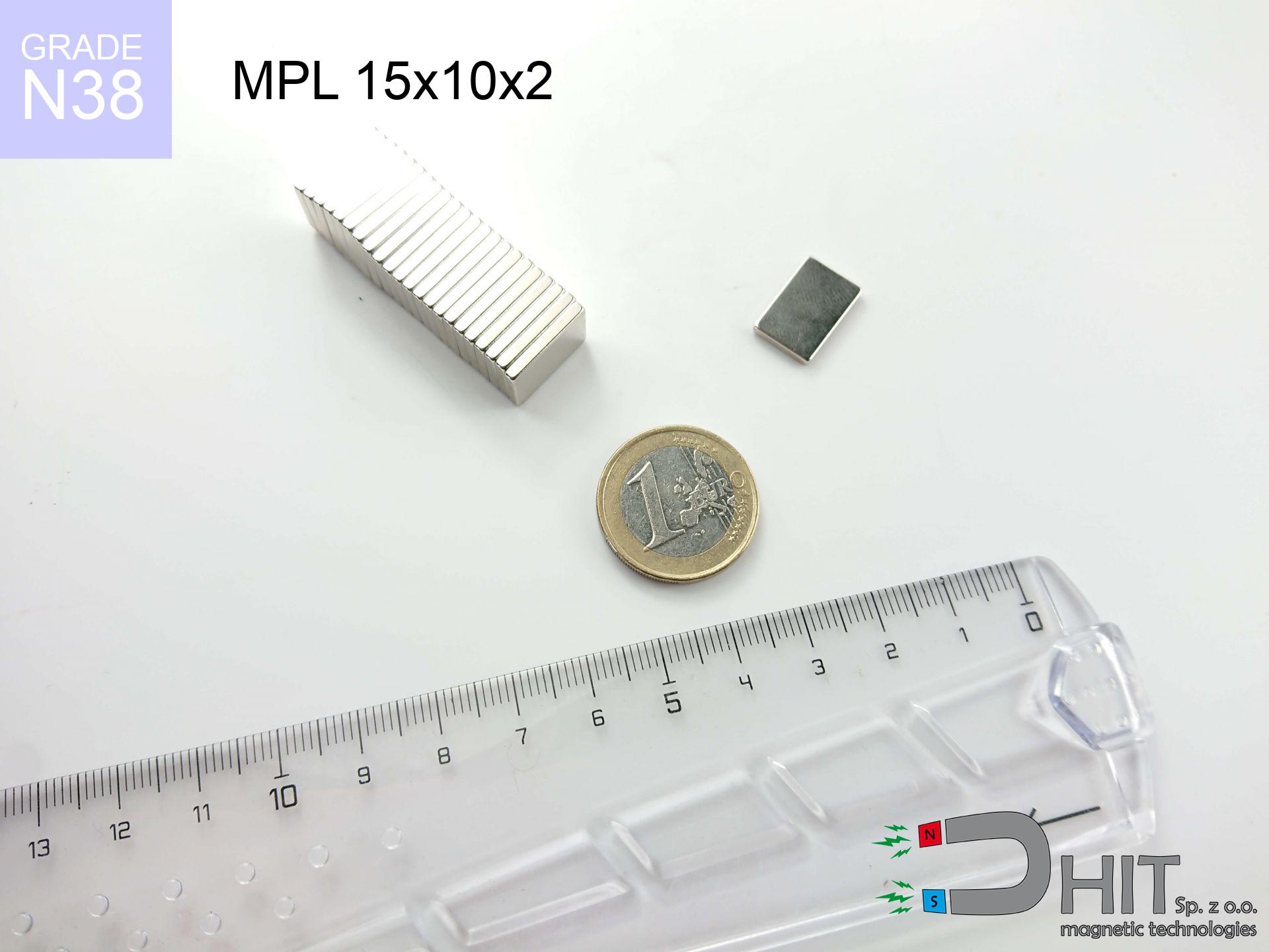
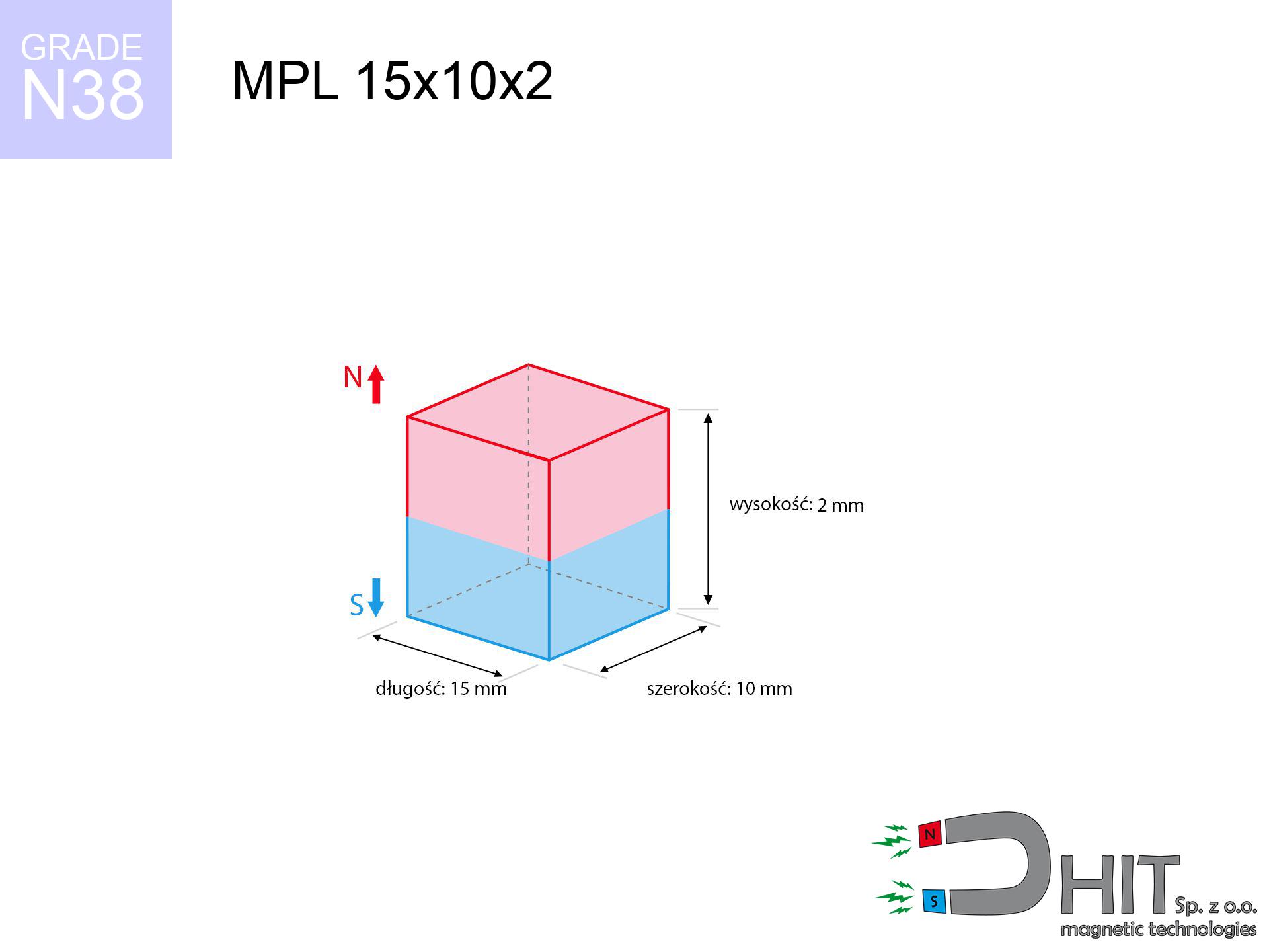
MPL 15x10x2 / N38 - lamellar magnet
lamellar magnet
Catalog no 020388
GTIN/EAN: 5906301811879
length
15 mm [±0,1 mm]
Width
10 mm [±0,1 mm]
Height
2 mm [±0,1 mm]
Weight
2.25 g
Magnetization Direction
↑ axial
Load capacity
1.57 kg / 15.45 N
Magnetic Induction
180.53 mT / 1805 Gs
Coating
[NiCuNi] Nickel
1.316 ZŁ with VAT / pcs + price for transport
1.070 ZŁ net + 23% VAT / pcs
bulk discounts:
Need more?
Give us a call
+48 888 99 98 98
if you prefer let us know through
our online form
the contact form page.
Weight as well as appearance of magnetic components can be analyzed with our
force calculator.
Same-day shipping for orders placed before 14:00.
Technical of the product - MPL 15x10x2 / N38 - lamellar magnet
Specification / characteristics - MPL 15x10x2 / N38 - lamellar magnet
| properties | values |
|---|---|
| Cat. no. | 020388 |
| GTIN/EAN | 5906301811879 |
| Production/Distribution | Dhit sp. z o.o. |
| Country of origin | Poland / China / Germany |
| Customs code | 85059029 |
| length | 15 mm [±0,1 mm] |
| Width | 10 mm [±0,1 mm] |
| Height | 2 mm [±0,1 mm] |
| Weight | 2.25 g |
| Magnetization Direction | ↑ axial |
| Load capacity ~ ? | 1.57 kg / 15.45 N |
| Magnetic Induction ~ ? | 180.53 mT / 1805 Gs |
| Coating | [NiCuNi] Nickel |
| Manufacturing Tolerance | ±0.1 mm |
Magnetic properties of material N38
| properties | values | units |
|---|---|---|
| remenance Br [min. - max.] ? | 12.2-12.6 | kGs |
| remenance Br [min. - max.] ? | 1220-1260 | mT |
| coercivity bHc ? | 10.8-11.5 | kOe |
| coercivity bHc ? | 860-915 | kA/m |
| actual internal force iHc | ≥ 12 | kOe |
| actual internal force iHc | ≥ 955 | kA/m |
| energy density [min. - max.] ? | 36-38 | BH max MGOe |
| energy density [min. - max.] ? | 287-303 | BH max KJ/m |
| max. temperature ? | ≤ 80 | °C |
Physical properties of sintered neodymium magnets Nd2Fe14B at 20°C
| properties | values | units |
|---|---|---|
| Vickers hardness | ≥550 | Hv |
| Density | ≥7.4 | g/cm3 |
| Curie Temperature TC | 312 - 380 | °C |
| Curie Temperature TF | 593 - 716 | °F |
| Specific resistance | 150 | μΩ⋅cm |
| Bending strength | 250 | MPa |
| Compressive strength | 1000~1100 | MPa |
| Thermal expansion parallel (∥) to orientation (M) | (3-4) x 10-6 | °C-1 |
| Thermal expansion perpendicular (⊥) to orientation (M) | -(1-3) x 10-6 | °C-1 |
| Young's modulus | 1.7 x 10⁴ | kg/mm² |
Engineering modeling of the assembly - technical parameters
These data represent the result of a engineering calculation. Results are based on models for the material Nd2Fe14B. Operational performance might slightly differ from theoretical values. Use these calculations as a supplementary guide when designing systems.
Table 1: Static force (force vs gap) - interaction chart
MPL 15x10x2 / N38
| Distance (mm) | Induction (Gauss) / mT | Pull Force (kg/lbs/g/N) | Risk Status |
|---|---|---|---|
| 0 mm |
1805 Gs
180.5 mT
|
1.57 kg / 3.46 pounds
1570.0 g / 15.4 N
|
safe |
| 1 mm |
1628 Gs
162.8 mT
|
1.28 kg / 2.82 pounds
1278.3 g / 12.5 N
|
safe |
| 2 mm |
1394 Gs
139.4 mT
|
0.94 kg / 2.06 pounds
936.3 g / 9.2 N
|
safe |
| 3 mm |
1152 Gs
115.2 mT
|
0.64 kg / 1.41 pounds
639.9 g / 6.3 N
|
safe |
| 5 mm |
751 Gs
75.1 mT
|
0.27 kg / 0.60 pounds
271.5 g / 2.7 N
|
safe |
| 10 mm |
262 Gs
26.2 mT
|
0.03 kg / 0.07 pounds
33.1 g / 0.3 N
|
safe |
| 15 mm |
110 Gs
11.0 mT
|
0.01 kg / 0.01 pounds
5.8 g / 0.1 N
|
safe |
| 20 mm |
54 Gs
5.4 mT
|
0.00 kg / 0.00 pounds
1.4 g / 0.0 N
|
safe |
| 30 mm |
18 Gs
1.8 mT
|
0.00 kg / 0.00 pounds
0.2 g / 0.0 N
|
safe |
| 50 mm |
4 Gs
0.4 mT
|
0.00 kg / 0.00 pounds
0.0 g / 0.0 N
|
safe |
Table 2: Shear force (wall)
MPL 15x10x2 / N38
| Distance (mm) | Friction coefficient | Pull Force (kg/lbs/g/N) |
|---|---|---|
| 0 mm | Stal (~0.2) |
0.31 kg / 0.69 pounds
314.0 g / 3.1 N
|
| 1 mm | Stal (~0.2) |
0.26 kg / 0.56 pounds
256.0 g / 2.5 N
|
| 2 mm | Stal (~0.2) |
0.19 kg / 0.41 pounds
188.0 g / 1.8 N
|
| 3 mm | Stal (~0.2) |
0.13 kg / 0.28 pounds
128.0 g / 1.3 N
|
| 5 mm | Stal (~0.2) |
0.05 kg / 0.12 pounds
54.0 g / 0.5 N
|
| 10 mm | Stal (~0.2) |
0.01 kg / 0.01 pounds
6.0 g / 0.1 N
|
| 15 mm | Stal (~0.2) |
0.00 kg / 0.00 pounds
2.0 g / 0.0 N
|
| 20 mm | Stal (~0.2) |
0.00 kg / 0.00 pounds
0.0 g / 0.0 N
|
| 30 mm | Stal (~0.2) |
0.00 kg / 0.00 pounds
0.0 g / 0.0 N
|
| 50 mm | Stal (~0.2) |
0.00 kg / 0.00 pounds
0.0 g / 0.0 N
|
Table 3: Wall mounting (shearing) - vertical pull
MPL 15x10x2 / N38
| Surface type | Friction coefficient / % Mocy | Max load (kg/lbs/g/N) |
|---|---|---|
| Raw steel |
µ = 0.3
30% Nominalnej Siły
|
0.47 kg / 1.04 pounds
471.0 g / 4.6 N
|
| Painted steel (standard) |
µ = 0.2
20% Nominalnej Siły
|
0.31 kg / 0.69 pounds
314.0 g / 3.1 N
|
| Oily/slippery steel |
µ = 0.1
10% Nominalnej Siły
|
0.16 kg / 0.35 pounds
157.0 g / 1.5 N
|
| Magnet with anti-slip rubber |
µ = 0.5
50% Nominalnej Siły
|
0.79 kg / 1.73 pounds
785.0 g / 7.7 N
|
Table 4: Material efficiency (saturation) - power losses
MPL 15x10x2 / N38
| Steel thickness (mm) | % power | Real pull force (kg/lbs/g/N) |
|---|---|---|
| 0.5 mm |
|
0.16 kg / 0.35 pounds
157.0 g / 1.5 N
|
| 1 mm |
|
0.39 kg / 0.87 pounds
392.5 g / 3.9 N
|
| 2 mm |
|
0.79 kg / 1.73 pounds
785.0 g / 7.7 N
|
| 3 mm |
|
1.18 kg / 2.60 pounds
1177.5 g / 11.6 N
|
| 5 mm |
|
1.57 kg / 3.46 pounds
1570.0 g / 15.4 N
|
| 10 mm |
|
1.57 kg / 3.46 pounds
1570.0 g / 15.4 N
|
| 11 mm |
|
1.57 kg / 3.46 pounds
1570.0 g / 15.4 N
|
| 12 mm |
|
1.57 kg / 3.46 pounds
1570.0 g / 15.4 N
|
Table 5: Working in heat (stability) - thermal limit
MPL 15x10x2 / N38
| Ambient temp. (°C) | Power loss | Remaining pull (kg/lbs/g/N) | Status |
|---|---|---|---|
| 20 °C | 0.0% |
1.57 kg / 3.46 pounds
1570.0 g / 15.4 N
|
OK |
| 40 °C | -2.2% |
1.54 kg / 3.39 pounds
1535.5 g / 15.1 N
|
OK |
| 60 °C | -4.4% |
1.50 kg / 3.31 pounds
1500.9 g / 14.7 N
|
|
| 80 °C | -6.6% |
1.47 kg / 3.23 pounds
1466.4 g / 14.4 N
|
|
| 100 °C | -28.8% |
1.12 kg / 2.46 pounds
1117.8 g / 11.0 N
|
Table 6: Two magnets (attraction) - field collision
MPL 15x10x2 / N38
| Gap (mm) | Attraction (kg/lbs) (N-S) | Lateral Force (kg/lbs/g/N) | Repulsion (kg/lbs) (N-N) |
|---|---|---|---|
| 0 mm |
3.01 kg / 6.64 pounds
3 196 Gs
|
0.45 kg / 1.00 pounds
452 g / 4.4 N
|
N/A |
| 1 mm |
2.76 kg / 6.09 pounds
3 456 Gs
|
0.41 kg / 0.91 pounds
414 g / 4.1 N
|
2.49 kg / 5.48 pounds
~0 Gs
|
| 2 mm |
2.45 kg / 5.41 pounds
3 257 Gs
|
0.37 kg / 0.81 pounds
368 g / 3.6 N
|
2.21 kg / 4.87 pounds
~0 Gs
|
| 3 mm |
2.12 kg / 4.68 pounds
3 029 Gs
|
0.32 kg / 0.70 pounds
318 g / 3.1 N
|
1.91 kg / 4.21 pounds
~0 Gs
|
| 5 mm |
1.49 kg / 3.30 pounds
2 543 Gs
|
0.22 kg / 0.49 pounds
224 g / 2.2 N
|
1.35 kg / 2.97 pounds
~0 Gs
|
| 10 mm |
0.52 kg / 1.15 pounds
1 501 Gs
|
0.08 kg / 0.17 pounds
78 g / 0.8 N
|
0.47 kg / 1.03 pounds
~0 Gs
|
| 20 mm |
0.06 kg / 0.14 pounds
524 Gs
|
0.01 kg / 0.02 pounds
10 g / 0.1 N
|
0.06 kg / 0.13 pounds
~0 Gs
|
| 50 mm |
0.00 kg / 0.00 pounds
60 Gs
|
0.00 kg / 0.00 pounds
0 g / 0.0 N
|
0.00 kg / 0.00 pounds
~0 Gs
|
| 60 mm |
0.00 kg / 0.00 pounds
37 Gs
|
0.00 kg / 0.00 pounds
0 g / 0.0 N
|
0.00 kg / 0.00 pounds
~0 Gs
|
| 70 mm |
0.00 kg / 0.00 pounds
24 Gs
|
0.00 kg / 0.00 pounds
0 g / 0.0 N
|
0.00 kg / 0.00 pounds
~0 Gs
|
| 80 mm |
0.00 kg / 0.00 pounds
16 Gs
|
0.00 kg / 0.00 pounds
0 g / 0.0 N
|
0.00 kg / 0.00 pounds
~0 Gs
|
| 90 mm |
0.00 kg / 0.00 pounds
12 Gs
|
0.00 kg / 0.00 pounds
0 g / 0.0 N
|
0.00 kg / 0.00 pounds
~0 Gs
|
| 100 mm |
0.00 kg / 0.00 pounds
9 Gs
|
0.00 kg / 0.00 pounds
0 g / 0.0 N
|
0.00 kg / 0.00 pounds
~0 Gs
|
Table 7: Protective zones (implants) - warnings
MPL 15x10x2 / N38
| Object / Device | Limit (Gauss) / mT | Safe distance |
|---|---|---|
| Pacemaker | 5 Gs (0.5 mT) | 5.0 cm |
| Hearing aid | 10 Gs (1.0 mT) | 4.0 cm |
| Mechanical watch | 20 Gs (2.0 mT) | 3.0 cm |
| Mobile device | 40 Gs (4.0 mT) | 2.5 cm |
| Car key | 50 Gs (5.0 mT) | 2.5 cm |
| Payment card | 400 Gs (40.0 mT) | 1.0 cm |
| HDD hard drive | 600 Gs (60.0 mT) | 1.0 cm |
Table 8: Dynamics (cracking risk) - warning
MPL 15x10x2 / N38
| Start from (mm) | Speed (km/h) | Energy (J) | Predicted outcome |
|---|---|---|---|
| 10 mm |
26.99 km/h
(7.50 m/s)
|
0.06 J | |
| 30 mm |
46.15 km/h
(12.82 m/s)
|
0.18 J | |
| 50 mm |
59.57 km/h
(16.55 m/s)
|
0.31 J | |
| 100 mm |
84.24 km/h
(23.40 m/s)
|
0.62 J |
Table 9: Coating parameters (durability)
MPL 15x10x2 / N38
| Technical parameter | Value / Description |
|---|---|
| Coating type | [NiCuNi] Nickel |
| Layer structure | Nickel - Copper - Nickel |
| Layer thickness | 10-20 µm |
| Salt spray test (SST) ? | 24 h |
| Recommended environment | Indoors only (dry) |
Table 10: Construction data (Pc)
MPL 15x10x2 / N38
| Parameter | Value | SI Unit / Description |
|---|---|---|
| Magnetic Flux | 3 194 Mx | 31.9 µWb |
| Pc Coefficient | 0.22 | Low (Flat) |
Table 11: Physics of underwater searching
MPL 15x10x2 / N38
| Environment | Effective steel pull | Effect |
|---|---|---|
| Air (land) | 1.57 kg | Standard |
| Water (riverbed) |
1.80 kg
(+0.23 kg buoyancy gain)
|
+14.5% |
1. Wall mount (shear)
*Caution: On a vertical wall, the magnet retains just ~20% of its max power.
2. Efficiency vs thickness
*Thin metal sheet (e.g. 0.5mm PC case) drastically limits the holding force.
3. Power loss vs temp
*For N38 material, the max working temp is 80°C.
4. Demagnetization curve and operating point (B-H)
chart generated for the permeance coefficient Pc (Permeance Coefficient) = 0.22
This simulation demonstrates the magnetic stability of the selected magnet under specific geometric conditions. The solid red line represents the demagnetization curve (material potential), while the dashed blue line is the load line based on the magnet's geometry. The Pc (Permeance Coefficient), also known as the load line slope, is a dimensionless value that describes the relationship between the magnet's shape and its magnetic stability. The intersection of these two lines (the black dot) is the operating point — it determines the actual magnetic flux density generated by the magnet in this specific configuration. A higher Pc value means the magnet is more 'slender' (tall relative to its area), resulting in a higher operating point and better resistance to irreversible demagnetization caused by external fields or temperature. A value of 0.42 is relatively low (typical for flat magnets), meaning the operating point is closer to the 'knee' of the curve — caution is advised when operating at temperatures near the maximum limit to avoid strength loss.
Material specification
| iron (Fe) | 64% – 68% |
| neodymium (Nd) | 29% – 32% |
| boron (B) | 1.1% – 1.2% |
| dysprosium (Dy) | 0.5% – 2.0% |
| coating (Ni-Cu-Ni) | < 0.05% |
Sustainability
| recyclability (EoL) | 100% |
| recycled raw materials | ~10% (pre-cons) |
| carbon footprint | low / zredukowany |
| waste code (EWC) | 16 02 16 |
See more offers

![UMP 97x40 [M8+M10] GW F300 kg / N38 - search holder](https://cdn3.dhit.pl/graphics/products/ump97x40-m8+m10-gw-f-300-kg-kic.jpg "UMP 97x40 [M8+M10] GW F300 kg / N38 - search holder")

![SM 25x300 [2xM8] / N42 - magnetic separator](https://cdn3.dhit.pl/graphics/products/sm-25x300-2xm8-kud.jpg "SM 25x300 [2xM8] / N42 - magnetic separator")
Advantages as well as disadvantages of rare earth magnets.
Pros
- They do not lose magnetism, even over around 10 years – the decrease in power is only ~1% (theoretically),
- Neodymium magnets are distinguished by highly resistant to loss of magnetic properties caused by external field sources,
- In other words, due to the smooth surface of gold, the element gains a professional look,
- Magnetic induction on the working layer of the magnet remains extremely intense,
- Due to their durability and thermal resistance, neodymium magnets are capable of operate (depending on the form) even at high temperatures reaching 230°C or more...
- Possibility of individual modeling as well as modifying to defined requirements,
- Fundamental importance in advanced technology sectors – they find application in mass storage devices, motor assemblies, diagnostic systems, as well as modern systems.
- Relatively small size with high pulling force – neodymium magnets offer impressive pulling force in compact dimensions, which enables their usage in miniature devices
Cons
- At very strong impacts they can crack, therefore we advise placing them in steel cases. A metal housing provides additional protection against damage, as well as increases the magnet's durability.
- NdFeB magnets demagnetize when exposed to high temperatures. After reaching 80°C, many of them experience permanent drop of strength (a factor is the shape as well as dimensions of the magnet). We offer magnets specially adapted to work at temperatures up to 230°C marked [AH], which are very resistant to heat
- When exposed to humidity, magnets usually rust. To use them in conditions outside, it is recommended to use protective magnets, such as those in rubber or plastics, which secure oxidation and corrosion.
- Limited ability of creating nuts in the magnet and complex shapes - preferred is a housing - mounting mechanism.
- Health risk resulting from small fragments of magnets pose a threat, when accidentally swallowed, which gains importance in the context of child safety. Additionally, small components of these products can complicate diagnosis medical in case of swallowing.
- High unit price – neodymium magnets are more expensive than other types of magnets (e.g. ferrite), which can limit application in large quantities
Lifting parameters
Maximum lifting force for a neodymium magnet – what contributes to it?
- using a sheet made of low-carbon steel, functioning as a magnetic yoke
- whose transverse dimension equals approx. 10 mm
- with a surface free of scratches
- under conditions of ideal adhesion (surface-to-surface)
- for force applied at a right angle (in the magnet axis)
- at temperature approx. 20 degrees Celsius
Magnet lifting force in use – key factors
- Distance – the presence of any layer (paint, tape, gap) interrupts the magnetic circuit, which reduces power steeply (even by 50% at 0.5 mm).
- Loading method – declared lifting capacity refers to pulling vertically. When slipping, the magnet exhibits much less (typically approx. 20-30% of nominal force).
- Element thickness – to utilize 100% power, the steel must be adequately massive. Thin sheet restricts the lifting capacity (the magnet "punches through" it).
- Material composition – not every steel reacts the same. High carbon content weaken the interaction with the magnet.
- Smoothness – ideal contact is possible only on smooth steel. Any scratches and bumps reduce the real contact area, reducing force.
- Temperature influence – high temperature weakens pulling force. Too high temperature can permanently demagnetize the magnet.
Holding force was checked on the plate surface of 20 mm thickness, when the force acted perpendicularly, in contrast under shearing force the lifting capacity is smaller. Additionally, even a minimal clearance between the magnet’s surface and the plate decreases the lifting capacity.
Safe handling of neodymium magnets
Threat to electronics
Avoid bringing magnets close to a purse, laptop, or TV. The magnetism can irreversibly ruin these devices and erase data from cards.
Bone fractures
Watch your fingers. Two powerful magnets will join immediately with a force of several hundred kilograms, crushing anything in their path. Exercise extreme caution!
Handling rules
Use magnets consciously. Their immense force can shock even professionals. Be vigilant and respect their power.
Product not for children
These products are not intended for children. Eating several magnets may result in them pinching intestinal walls, which constitutes a direct threat to life and requires urgent medical intervention.
Magnet fragility
Watch out for shards. Magnets can fracture upon violent connection, ejecting shards into the air. We recommend safety glasses.
Mechanical processing
Fire warning: Neodymium dust is explosive. Avoid machining magnets in home conditions as this risks ignition.
Do not overheat magnets
Keep cool. Neodymium magnets are sensitive to temperature. If you need resistance above 80°C, look for HT versions (H, SH, UH).
ICD Warning
For implant holders: Powerful magnets disrupt medical devices. Keep at least 30 cm distance or request help to work with the magnets.
Allergic reactions
Studies show that the nickel plating (standard magnet coating) is a common allergen. If your skin reacts to metals, refrain from touching magnets with bare hands or choose coated magnets.
Compass and GPS
Be aware: rare earth magnets generate a field that confuses sensitive sensors. Keep a separation from your phone, device, and navigation systems.
Tabela kosztu i czasu dostawy
Płatność przed wysyłką:

GLS kurier
Przesyłka będzie u Ciebie za 2-3 dni
14.99 ZŁ

InPost Paczkomaty 24/7
Przesyłka będzie u Ciebie za 1-2 dni
12.30 ZŁ
Płatność przy odbiorze (pobranie):
GLS kurier
Przesyłka będzie u Ciebie za 1-2 dni
23.00 ZŁ
Rate the product
Your rating