
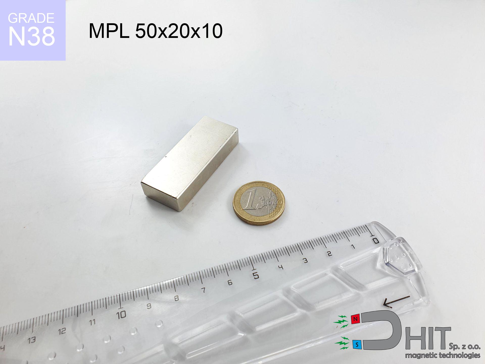
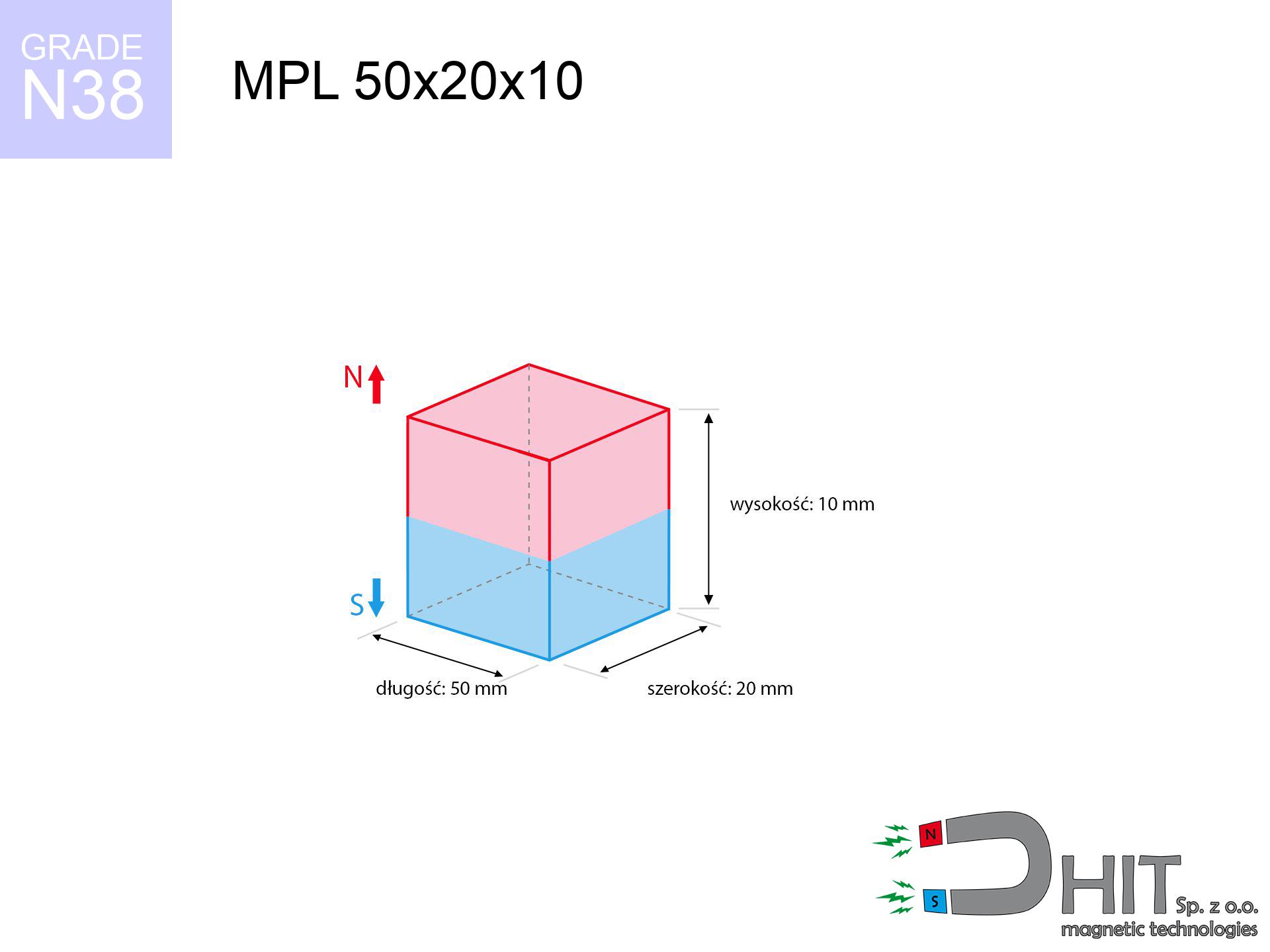
MPL 50x20x10 / N38 - lamellar magnet
lamellar magnet
Catalog no 020165
GTIN/EAN: 5906301811718
length
50 mm [±0,1 mm]
Width
20 mm [±0,1 mm]
Height
10 mm [±0,1 mm]
Weight
75 g
Magnetization Direction
↑ axial
Load capacity
29.99 kg / 294.15 N
Magnetic Induction
337.18 mT / 3372 Gs
Coating
[NiCuNi] Nickel
43.05 ZŁ with VAT / pcs + price for transport
35.00 ZŁ net + 23% VAT / pcs
bulk discounts:
Need more?Engineering report for this magnet
Full PDF analysis: pull and shear force, effect of distance, temperature and plate thickness, safety distances and the demagnetization curve.
Give us a call
+48 22 499 98 98
or let us know using
contact form
our website.
Specifications along with structure of magnetic components can be reviewed using our
power calculator.
Order by 14:00 and we’ll ship today!
Technical - MPL 50x20x10 / N38 - lamellar magnet
Specification / characteristics - MPL 50x20x10 / N38 - lamellar magnet
| properties | values |
|---|---|
| Cat. no. | 020165 |
| GTIN/EAN | 5906301811718 |
| Production/Distribution | Dhit sp. z o.o. |
| Country of origin | Poland / China / Germany |
| Customs code | 85059029 |
| length | 50 mm [±0,1 mm] |
| Width | 20 mm [±0,1 mm] |
| Height | 10 mm [±0,1 mm] |
| Weight | 75 g |
| Magnetization Direction | ↑ axial |
| Load capacity ~ ? | 29.99 kg / 294.15 N |
| Magnetic Induction ~ ? | 337.18 mT / 3372 Gs |
| Coating | [NiCuNi] Nickel |
| Manufacturing Tolerance | ±0.1 mm |
Magnetic properties of material N38
| properties | values | units |
|---|---|---|
| remenance Br [min. - max.] ? | 12.2-12.6 | kGs |
| remenance Br [min. - max.] ? | 1220-1260 | mT |
| coercivity bHc ? | 10.8-11.5 | kOe |
| coercivity bHc ? | 860-915 | kA/m |
| actual internal force iHc | ≥ 12 | kOe |
| actual internal force iHc | ≥ 955 | kA/m |
| energy density [min. - max.] ? | 36-38 | BH max MGOe |
| energy density [min. - max.] ? | 287-303 | BH max KJ/m |
| max. temperature ? | ≤ 80 | °C |
Physical properties of sintered neodymium magnets Nd2Fe14B at 20°C
| properties | values | units |
|---|---|---|
| Vickers hardness | ≥550 | Hv |
| Density | ≥7.4 | g/cm3 |
| Curie Temperature TC | 312 - 380 | °C |
| Curie Temperature TF | 593 - 716 | °F |
| Specific resistance | 150 | μΩ⋅cm |
| Bending strength | 250 | MPa |
| Compressive strength | 1000~1100 | MPa |
| Thermal expansion parallel (∥) to orientation (M) | (3-4) x 10-6 | °C-1 |
| Thermal expansion perpendicular (⊥) to orientation (M) | -(1-3) x 10-6 | °C-1 |
| Young's modulus | 1.7 x 10⁴ | kg/mm² |
Engineering modeling of the magnet - report
Presented information constitute the result of a engineering calculation. Results were calculated on algorithms for the material Nd2Fe14B. Real-world parameters may differ. Please consider these calculations as a supplementary guide when designing systems.
Table 1: Static pull force (pull vs gap) - interaction chart
MPL 50x20x10 / N38
| Distance (mm) | Induction (Gauss) / mT | Pull Force (kg/lbs/g/N) | Risk Status |
|---|---|---|---|
| 0 mm |
3371 Gs
337.1 mT
|
29.99 kg / 66.12 pounds
29990.0 g / 294.2 N
|
critical level |
| 1 mm |
3158 Gs
315.8 mT
|
26.32 kg / 58.03 pounds
26323.3 g / 258.2 N
|
critical level |
| 2 mm |
2932 Gs
293.2 mT
|
22.69 kg / 50.02 pounds
22687.6 g / 222.6 N
|
critical level |
| 3 mm |
2703 Gs
270.3 mT
|
19.29 kg / 42.52 pounds
19286.7 g / 189.2 N
|
critical level |
| 5 mm |
2266 Gs
226.6 mT
|
13.55 kg / 29.86 pounds
13546.3 g / 132.9 N
|
critical level |
| 10 mm |
1419 Gs
141.9 mT
|
5.31 kg / 11.71 pounds
5313.0 g / 52.1 N
|
warning |
| 15 mm |
908 Gs
90.8 mT
|
2.17 kg / 4.79 pounds
2174.5 g / 21.3 N
|
warning |
| 20 mm |
603 Gs
60.3 mT
|
0.96 kg / 2.12 pounds
961.0 g / 9.4 N
|
safe |
| 30 mm |
296 Gs
29.6 mT
|
0.23 kg / 0.51 pounds
231.0 g / 2.3 N
|
safe |
| 50 mm |
97 Gs
9.7 mT
|
0.02 kg / 0.05 pounds
24.8 g / 0.2 N
|
safe |
Table 2: Slippage load (wall)
MPL 50x20x10 / N38
| Distance (mm) | Friction coefficient | Pull Force (kg/lbs/g/N) |
|---|---|---|
| 0 mm | Stal (~0.2) |
6.00 kg / 13.22 pounds
5998.0 g / 58.8 N
|
| 1 mm | Stal (~0.2) |
5.26 kg / 11.61 pounds
5264.0 g / 51.6 N
|
| 2 mm | Stal (~0.2) |
4.54 kg / 10.00 pounds
4538.0 g / 44.5 N
|
| 3 mm | Stal (~0.2) |
3.86 kg / 8.51 pounds
3858.0 g / 37.8 N
|
| 5 mm | Stal (~0.2) |
2.71 kg / 5.97 pounds
2710.0 g / 26.6 N
|
| 10 mm | Stal (~0.2) |
1.06 kg / 2.34 pounds
1062.0 g / 10.4 N
|
| 15 mm | Stal (~0.2) |
0.43 kg / 0.96 pounds
434.0 g / 4.3 N
|
| 20 mm | Stal (~0.2) |
0.19 kg / 0.42 pounds
192.0 g / 1.9 N
|
| 30 mm | Stal (~0.2) |
0.05 kg / 0.10 pounds
46.0 g / 0.5 N
|
| 50 mm | Stal (~0.2) |
0.00 kg / 0.01 pounds
4.0 g / 0.0 N
|
Table 3: Wall mounting (shearing) - vertical pull
MPL 50x20x10 / N38
| Surface type | Friction coefficient / % Mocy | Max load (kg/lbs/g/N) |
|---|---|---|
| Raw steel |
µ = 0.3
30% Nominalnej Siły
|
9.00 kg / 19.83 pounds
8997.0 g / 88.3 N
|
| Painted steel (standard) |
µ = 0.2
20% Nominalnej Siły
|
6.00 kg / 13.22 pounds
5998.0 g / 58.8 N
|
| Oily/slippery steel |
µ = 0.1
10% Nominalnej Siły
|
3.00 kg / 6.61 pounds
2999.0 g / 29.4 N
|
| Magnet with anti-slip rubber |
µ = 0.5
50% Nominalnej Siły
|
15.00 kg / 33.06 pounds
14995.0 g / 147.1 N
|
Table 4: Steel thickness (saturation) - power losses
MPL 50x20x10 / N38
| Steel thickness (mm) | % power | Real pull force (kg/lbs/g/N) |
|---|---|---|
| 0.5 mm |
|
1.50 kg / 3.31 pounds
1499.5 g / 14.7 N
|
| 1 mm |
|
3.75 kg / 8.26 pounds
3748.8 g / 36.8 N
|
| 2 mm |
|
7.50 kg / 16.53 pounds
7497.5 g / 73.6 N
|
| 3 mm |
|
11.25 kg / 24.79 pounds
11246.3 g / 110.3 N
|
| 5 mm |
|
18.74 kg / 41.32 pounds
18743.8 g / 183.9 N
|
| 10 mm |
|
29.99 kg / 66.12 pounds
29990.0 g / 294.2 N
|
| 11 mm |
|
29.99 kg / 66.12 pounds
29990.0 g / 294.2 N
|
| 12 mm |
|
29.99 kg / 66.12 pounds
29990.0 g / 294.2 N
|
Table 5: Working in heat (stability) - resistance threshold
MPL 50x20x10 / N38
| Ambient temp. (°C) | Power loss | Remaining pull (kg/lbs/g/N) | Status |
|---|---|---|---|
| 20 °C | 0.0% |
29.99 kg / 66.12 pounds
29990.0 g / 294.2 N
|
OK |
| 40 °C | -2.2% |
29.33 kg / 64.66 pounds
29330.2 g / 287.7 N
|
OK |
| 60 °C | -4.4% |
28.67 kg / 63.21 pounds
28670.4 g / 281.3 N
|
|
| 80 °C | -6.6% |
28.01 kg / 61.75 pounds
28010.7 g / 274.8 N
|
|
| 100 °C | -28.8% |
21.35 kg / 47.07 pounds
21352.9 g / 209.5 N
|
Table 6: Two magnets (attraction) - field collision
MPL 50x20x10 / N38
| Gap (mm) | Attraction (kg/lbs) (N-S) | Shear Strength (kg/lbs/g/N) | Repulsion (kg/lbs) (N-N) |
|---|---|---|---|
| 0 mm |
70.06 kg / 154.45 pounds
4 789 Gs
|
10.51 kg / 23.17 pounds
10509 g / 103.1 N
|
N/A |
| 1 mm |
65.83 kg / 145.13 pounds
6 535 Gs
|
9.87 kg / 21.77 pounds
9874 g / 96.9 N
|
59.25 kg / 130.61 pounds
~0 Gs
|
| 2 mm |
61.49 kg / 135.57 pounds
6 316 Gs
|
9.22 kg / 20.34 pounds
9224 g / 90.5 N
|
55.34 kg / 122.01 pounds
~0 Gs
|
| 3 mm |
57.20 kg / 126.10 pounds
6 092 Gs
|
8.58 kg / 18.92 pounds
8580 g / 84.2 N
|
51.48 kg / 113.49 pounds
~0 Gs
|
| 5 mm |
48.94 kg / 107.89 pounds
5 635 Gs
|
7.34 kg / 16.18 pounds
7341 g / 72.0 N
|
44.05 kg / 97.10 pounds
~0 Gs
|
| 10 mm |
31.64 kg / 69.76 pounds
4 531 Gs
|
4.75 kg / 10.46 pounds
4747 g / 46.6 N
|
28.48 kg / 62.79 pounds
~0 Gs
|
| 20 mm |
12.41 kg / 27.36 pounds
2 838 Gs
|
1.86 kg / 4.10 pounds
1862 g / 18.3 N
|
11.17 kg / 24.63 pounds
~0 Gs
|
| 50 mm |
1.07 kg / 2.35 pounds
832 Gs
|
0.16 kg / 0.35 pounds
160 g / 1.6 N
|
0.96 kg / 2.12 pounds
~0 Gs
|
| 60 mm |
0.54 kg / 1.19 pounds
592 Gs
|
0.08 kg / 0.18 pounds
81 g / 0.8 N
|
0.49 kg / 1.07 pounds
~0 Gs
|
| 70 mm |
0.29 kg / 0.64 pounds
433 Gs
|
0.04 kg / 0.10 pounds
43 g / 0.4 N
|
0.26 kg / 0.57 pounds
~0 Gs
|
| 80 mm |
0.16 kg / 0.36 pounds
324 Gs
|
0.02 kg / 0.05 pounds
24 g / 0.2 N
|
0.15 kg / 0.32 pounds
~0 Gs
|
| 90 mm |
0.10 kg / 0.21 pounds
248 Gs
|
0.01 kg / 0.03 pounds
14 g / 0.1 N
|
0.09 kg / 0.19 pounds
~0 Gs
|
| 100 mm |
0.06 kg / 0.13 pounds
194 Gs
|
0.01 kg / 0.02 pounds
9 g / 0.1 N
|
0.05 kg / 0.11 pounds
~0 Gs
|
Table 7: Safety (HSE) (implants) - warnings
MPL 50x20x10 / N38
| Object / Device | Limit (Gauss) / mT | Safe distance |
|---|---|---|
| Pacemaker | 5 Gs (0.5 mT) | 15.5 cm |
| Hearing aid | 10 Gs (1.0 mT) | 12.0 cm |
| Timepiece | 20 Gs (2.0 mT) | 9.5 cm |
| Phone / Smartphone | 40 Gs (4.0 mT) | 7.5 cm |
| Car key | 50 Gs (5.0 mT) | 7.0 cm |
| Payment card | 400 Gs (40.0 mT) | 3.0 cm |
| HDD hard drive | 600 Gs (60.0 mT) | 2.5 cm |
Table 8: Dynamics (cracking risk) - collision effects
MPL 50x20x10 / N38
| Start from (mm) | Speed (km/h) | Energy (J) | Predicted outcome |
|---|---|---|---|
| 10 mm |
22.29 km/h
(6.19 m/s)
|
1.44 J | |
| 30 mm |
35.10 km/h
(9.75 m/s)
|
3.56 J | |
| 50 mm |
45.12 km/h
(12.53 m/s)
|
5.89 J | |
| 100 mm |
63.77 km/h
(17.72 m/s)
|
11.77 J |
Table 9: Surface protection spec
MPL 50x20x10 / N38
| Technical parameter | Value / Description |
|---|---|
| Coating type | [NiCuNi] Nickel |
| Layer structure | Nickel - Copper - Nickel |
| Layer thickness | 10-20 µm |
| Salt spray test (SST) ? | 24 h |
| Recommended environment | Indoors only (dry) |
Table 10: Electrical data (Pc)
MPL 50x20x10 / N38
| Parameter | Value | SI Unit / Description |
|---|---|---|
| Magnetic Flux | 32 980 Mx | 329.8 µWb |
| Pc Coefficient | 0.38 | Low (Flat) |
Table 11: Submerged application
MPL 50x20x10 / N38
| Environment | Effective steel pull | Effect |
|---|---|---|
| Air (land) | 29.99 kg | Standard |
| Water (riverbed) |
34.34 kg
(+4.35 kg buoyancy gain)
|
+14.5% |
1. Shear force
*Caution: On a vertical surface, the magnet holds only approx. 20-30% of its nominal pull.
2. Steel saturation
*Thin steel (e.g. 0.5mm PC case) severely reduces the holding force.
3. Thermal stability
*For N38 material, the critical limit is 80°C.
4. Demagnetization curve and operating point (B-H)
chart generated for the permeance coefficient Pc (Permeance Coefficient) = 0.38
The chart above illustrates the magnetic characteristics of the material within the second quadrant of the hysteresis loop. The solid red line represents the demagnetization curve (material potential), while the dashed blue line is the load line based on the magnet's geometry. The Pc (Permeance Coefficient), also known as the load line slope, is a dimensionless value that describes the relationship between the magnet's shape and its magnetic stability. The intersection of these two lines (the black dot) is the operating point — it determines the actual magnetic flux density generated by the magnet in this specific configuration. A higher Pc value means the magnet is more 'slender' (tall relative to its area), resulting in a higher operating point and better resistance to irreversible demagnetization caused by external fields or temperature. A value of 0.42 is relatively low (typical for flat magnets), meaning the operating point is closer to the 'knee' of the curve — caution is advised when operating at temperatures near the maximum limit to avoid strength loss.
Chemical composition
| iron (Fe) | 64% – 68% |
| neodymium (Nd) | 29% – 32% |
| boron (B) | 1.1% – 1.2% |
| dysprosium (Dy) | 0.5% – 2.0% |
| coating (Ni-Cu-Ni) | < 0.05% |
Sustainability
| recyclability (EoL) | 100% |
| recycled raw materials | ~10% (pre-cons) |
| carbon footprint | low / zredukowany |
| waste code (EWC) | 16 02 16 |
See also proposals


Pros as well as cons of Nd2Fe14B magnets.
Pros
- They retain attractive force for nearly 10 years – the drop is just ~1% (according to analyses),
- They are noted for resistance to demagnetization induced by external disturbances,
- The use of an refined finish of noble metals (nickel, gold, silver) causes the element to be more visually attractive,
- They show high magnetic induction at the operating surface, which improves attraction properties,
- Through (appropriate) combination of ingredients, they can achieve high thermal resistance, enabling functioning at temperatures reaching 230°C and above...
- Due to the ability of precise molding and customization to individualized needs, magnetic components can be modeled in a variety of shapes and sizes, which makes them more universal,
- Universal use in electronics industry – they are commonly used in HDD drives, drive modules, precision medical tools, also multitasking production systems.
- Thanks to concentrated force, small magnets offer high operating force, occupying minimum space,
Limitations
- Brittleness is one of their disadvantages. Upon strong impact they can break. We recommend keeping them in a special holder, which not only secures them against impacts but also increases their durability
- NdFeB magnets lose force when exposed to high temperatures. After reaching 80°C, many of them experience permanent weakening of power (a factor is the shape as well as dimensions of the magnet). We offer magnets specially adapted to work at temperatures up to 230°C marked [AH], which are very resistant to heat
- Magnets exposed to a humid environment can corrode. Therefore during using outdoors, we advise using water-impermeable magnets made of rubber, plastic or other material resistant to moisture
- Due to limitations in realizing threads and complex shapes in magnets, we propose using casing - magnetic mount.
- Health risk resulting from small fragments of magnets pose a threat, in case of ingestion, which gains importance in the context of child safety. Additionally, tiny parts of these magnets can disrupt the diagnostic process medical when they are in the body.
- Due to complex production process, their price is higher than average,
Pull force analysis
Maximum lifting capacity of the magnet – what affects it?
- on a block made of structural steel, optimally conducting the magnetic field
- whose transverse dimension equals approx. 10 mm
- with a surface free of scratches
- without any air gap between the magnet and steel
- for force applied at a right angle (in the magnet axis)
- at conditions approx. 20°C
Lifting capacity in practice – influencing factors
- Gap between magnet and steel – even a fraction of a millimeter of separation (caused e.g. by veneer or dirt) diminishes the magnet efficiency, often by half at just 0.5 mm.
- Force direction – catalog parameter refers to detachment vertically. When applying parallel force, the magnet exhibits significantly lower power (typically approx. 20-30% of maximum force).
- Substrate thickness – for full efficiency, the steel must be sufficiently thick. Thin sheet restricts the lifting capacity (the magnet "punches through" it).
- Chemical composition of the base – mild steel gives the best results. Alloy steels reduce magnetic properties and lifting capacity.
- Surface finish – full contact is obtained only on smooth steel. Any scratches and bumps create air cushions, reducing force.
- Thermal environment – heating the magnet causes a temporary drop of force. It is worth remembering the thermal limit for a given model.
Lifting capacity testing was performed on a smooth plate of suitable thickness, under a perpendicular pulling force, whereas under shearing force the holding force is lower. Moreover, even a minimal clearance between the magnet’s surface and the plate lowers the load capacity.
Safety rules for work with neodymium magnets
Handling guide
Handle magnets consciously. Their powerful strength can surprise even professionals. Plan your moves and do not underestimate their force.
Sensitization to coating
It is widely known that the nickel plating (the usual finish) is a common allergen. If your skin reacts to metals, prevent direct skin contact or select encased magnets.
Keep away from children
Always store magnets out of reach of children. Risk of swallowing is significant, and the effects of magnets connecting inside the body are fatal.
Crushing risk
Large magnets can break fingers in a fraction of a second. Under no circumstances put your hand between two attracting surfaces.
Danger to pacemakers
For implant holders: Powerful magnets affect electronics. Keep at least 30 cm distance or request help to handle the magnets.
Keep away from electronics
Navigation devices and smartphones are extremely susceptible to magnetic fields. Close proximity with a powerful NdFeB magnet can permanently damage the internal compass in your phone.
Beware of splinters
Neodymium magnets are ceramic materials, meaning they are very brittle. Impact of two magnets will cause them breaking into small pieces.
Safe distance
Powerful magnetic fields can erase data on credit cards, HDDs, and other magnetic media. Keep a distance of at least 10 cm.
Heat sensitivity
Watch the temperature. Heating the magnet to high heat will permanently weaken its magnetic structure and strength.
Dust is flammable
Machining of NdFeB material carries a risk of fire hazard. Magnetic powder reacts violently with oxygen and is hard to extinguish.
Tabela kosztu i czasu dostawy
Płatność przed wysyłką:

GLS kurier
Przesyłka będzie u Ciebie za 2-3 dni
14.99 ZŁ

InPost Paczkomaty 24/7
Przesyłka będzie u Ciebie za 1-2 dni
12.30 ZŁ
Płatność przy odbiorze (pobranie):
GLS kurier
Przesyłka będzie u Ciebie za 1-2 dni
23.00 ZŁ
Rate the product
Your rating