
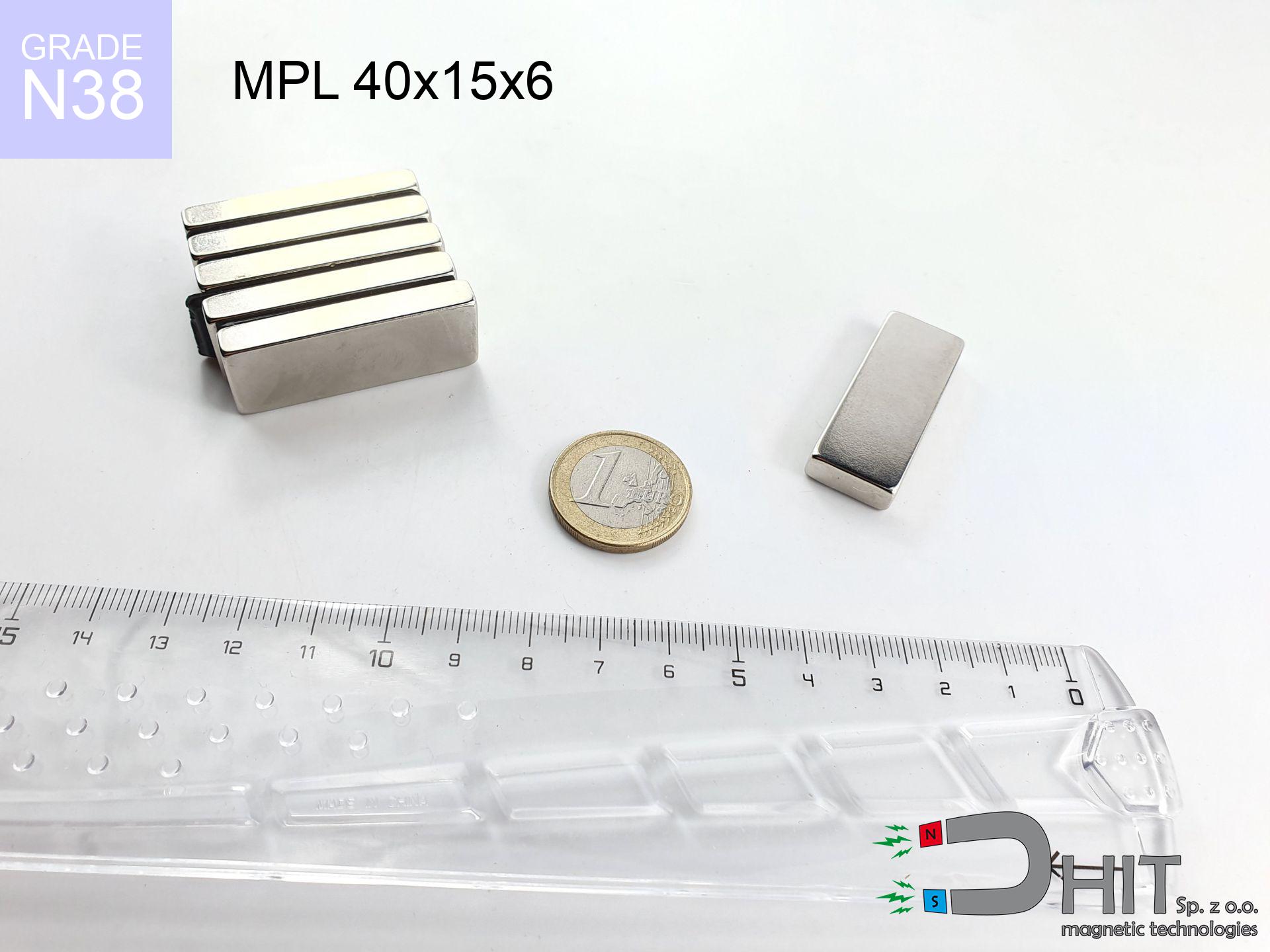
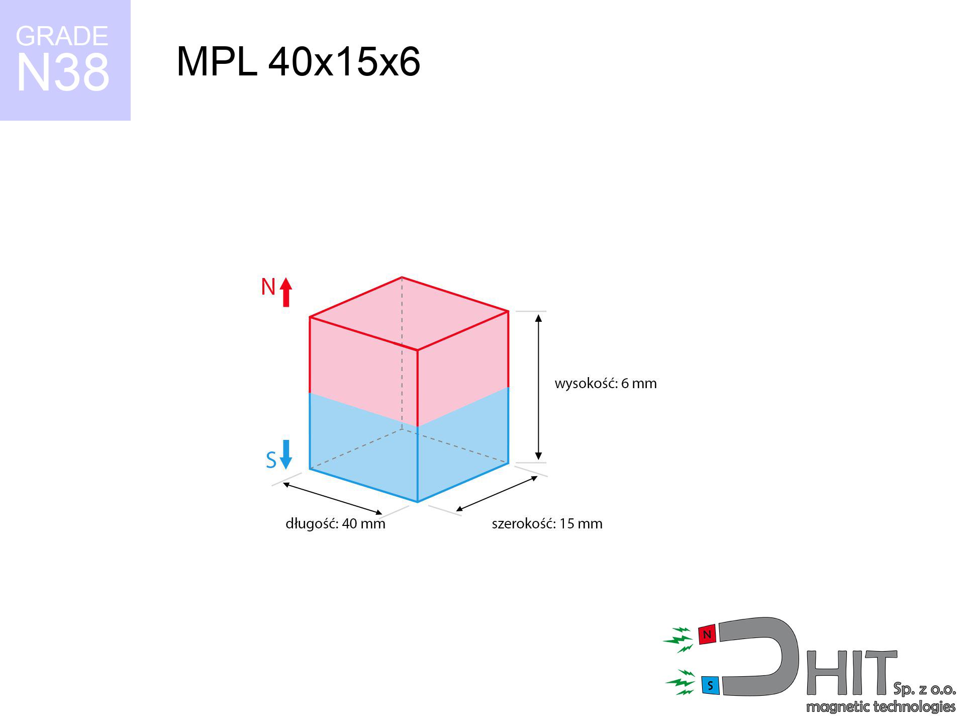
MPL 40x15x6 / N38 - lamellar magnet
lamellar magnet
Catalog no 020155
GTIN/EAN: 5906301811619
length
40 mm [±0,1 mm]
Width
15 mm [±0,1 mm]
Height
6 mm [±0,1 mm]
Weight
27 g
Magnetization Direction
↑ axial
Load capacity
14.21 kg / 139.45 N
Magnetic Induction
286.36 mT / 2864 Gs
Coating
[NiCuNi] Nickel
18.45 ZŁ with VAT / pcs + price for transport
15.00 ZŁ net + 23% VAT / pcs
bulk discounts:
Need more?
Call us now
+48 22 499 98 98
alternatively contact us through
our online form
our website.
Parameters and shape of neodymium magnets can be analyzed using our
force calculator.
Order by 14:00 and we’ll ship today!
Technical details - MPL 40x15x6 / N38 - lamellar magnet
Specification / characteristics - MPL 40x15x6 / N38 - lamellar magnet
| properties | values |
|---|---|
| Cat. no. | 020155 |
| GTIN/EAN | 5906301811619 |
| Production/Distribution | Dhit sp. z o.o. |
| Country of origin | Poland / China / Germany |
| Customs code | 85059029 |
| length | 40 mm [±0,1 mm] |
| Width | 15 mm [±0,1 mm] |
| Height | 6 mm [±0,1 mm] |
| Weight | 27 g |
| Magnetization Direction | ↑ axial |
| Load capacity ~ ? | 14.21 kg / 139.45 N |
| Magnetic Induction ~ ? | 286.36 mT / 2864 Gs |
| Coating | [NiCuNi] Nickel |
| Manufacturing Tolerance | ±0.1 mm |
Magnetic properties of material N38
| properties | values | units |
|---|---|---|
| remenance Br [min. - max.] ? | 12.2-12.6 | kGs |
| remenance Br [min. - max.] ? | 1220-1260 | mT |
| coercivity bHc ? | 10.8-11.5 | kOe |
| coercivity bHc ? | 860-915 | kA/m |
| actual internal force iHc | ≥ 12 | kOe |
| actual internal force iHc | ≥ 955 | kA/m |
| energy density [min. - max.] ? | 36-38 | BH max MGOe |
| energy density [min. - max.] ? | 287-303 | BH max KJ/m |
| max. temperature ? | ≤ 80 | °C |
Physical properties of sintered neodymium magnets Nd2Fe14B at 20°C
| properties | values | units |
|---|---|---|
| Vickers hardness | ≥550 | Hv |
| Density | ≥7.4 | g/cm3 |
| Curie Temperature TC | 312 - 380 | °C |
| Curie Temperature TF | 593 - 716 | °F |
| Specific resistance | 150 | μΩ⋅cm |
| Bending strength | 250 | MPa |
| Compressive strength | 1000~1100 | MPa |
| Thermal expansion parallel (∥) to orientation (M) | (3-4) x 10-6 | °C-1 |
| Thermal expansion perpendicular (⊥) to orientation (M) | -(1-3) x 10-6 | °C-1 |
| Young's modulus | 1.7 x 10⁴ | kg/mm² |
Engineering modeling of the product - technical parameters
The following values constitute the result of a mathematical simulation. Results are based on algorithms for the material Nd2Fe14B. Real-world parameters may differ from theoretical values. Use these data as a supplementary guide when designing systems.
Table 1: Static force (pull vs distance) - power drop
MPL 40x15x6 / N38
| Distance (mm) | Induction (Gauss) / mT | Pull Force (kg/lbs/g/N) | Risk Status |
|---|---|---|---|
| 0 mm |
2863 Gs
286.3 mT
|
14.21 kg / 31.33 lbs
14210.0 g / 139.4 N
|
critical level |
| 1 mm |
2635 Gs
263.5 mT
|
12.04 kg / 26.55 lbs
12041.8 g / 118.1 N
|
critical level |
| 2 mm |
2385 Gs
238.5 mT
|
9.86 kg / 21.74 lbs
9859.1 g / 96.7 N
|
warning |
| 3 mm |
2132 Gs
213.2 mT
|
7.88 kg / 17.37 lbs
7880.1 g / 77.3 N
|
warning |
| 5 mm |
1670 Gs
167.0 mT
|
4.84 kg / 10.66 lbs
4837.1 g / 47.5 N
|
warning |
| 10 mm |
903 Gs
90.3 mT
|
1.41 kg / 3.11 lbs
1412.2 g / 13.9 N
|
weak grip |
| 15 mm |
520 Gs
52.0 mT
|
0.47 kg / 1.03 lbs
469.2 g / 4.6 N
|
weak grip |
| 20 mm |
320 Gs
32.0 mT
|
0.18 kg / 0.39 lbs
177.7 g / 1.7 N
|
weak grip |
| 30 mm |
141 Gs
14.1 mT
|
0.03 kg / 0.08 lbs
34.5 g / 0.3 N
|
weak grip |
| 50 mm |
41 Gs
4.1 mT
|
0.00 kg / 0.01 lbs
3.0 g / 0.0 N
|
weak grip |
Table 2: Vertical force (wall)
MPL 40x15x6 / N38
| Distance (mm) | Friction coefficient | Pull Force (kg/lbs/g/N) |
|---|---|---|
| 0 mm | Stal (~0.2) |
2.84 kg / 6.27 lbs
2842.0 g / 27.9 N
|
| 1 mm | Stal (~0.2) |
2.41 kg / 5.31 lbs
2408.0 g / 23.6 N
|
| 2 mm | Stal (~0.2) |
1.97 kg / 4.35 lbs
1972.0 g / 19.3 N
|
| 3 mm | Stal (~0.2) |
1.58 kg / 3.47 lbs
1576.0 g / 15.5 N
|
| 5 mm | Stal (~0.2) |
0.97 kg / 2.13 lbs
968.0 g / 9.5 N
|
| 10 mm | Stal (~0.2) |
0.28 kg / 0.62 lbs
282.0 g / 2.8 N
|
| 15 mm | Stal (~0.2) |
0.09 kg / 0.21 lbs
94.0 g / 0.9 N
|
| 20 mm | Stal (~0.2) |
0.04 kg / 0.08 lbs
36.0 g / 0.4 N
|
| 30 mm | Stal (~0.2) |
0.01 kg / 0.01 lbs
6.0 g / 0.1 N
|
| 50 mm | Stal (~0.2) |
0.00 kg / 0.00 lbs
0.0 g / 0.0 N
|
Table 3: Wall mounting (sliding) - behavior on slippery surfaces
MPL 40x15x6 / N38
| Surface type | Friction coefficient / % Mocy | Max load (kg/lbs/g/N) |
|---|---|---|
| Raw steel |
µ = 0.3
30% Nominalnej Siły
|
4.26 kg / 9.40 lbs
4263.0 g / 41.8 N
|
| Painted steel (standard) |
µ = 0.2
20% Nominalnej Siły
|
2.84 kg / 6.27 lbs
2842.0 g / 27.9 N
|
| Oily/slippery steel |
µ = 0.1
10% Nominalnej Siły
|
1.42 kg / 3.13 lbs
1421.0 g / 13.9 N
|
| Magnet with anti-slip rubber |
µ = 0.5
50% Nominalnej Siły
|
7.11 kg / 15.66 lbs
7105.0 g / 69.7 N
|
Table 4: Steel thickness (saturation) - sheet metal selection
MPL 40x15x6 / N38
| Steel thickness (mm) | % power | Real pull force (kg/lbs/g/N) |
|---|---|---|
| 0.5 mm |
|
0.71 kg / 1.57 lbs
710.5 g / 7.0 N
|
| 1 mm |
|
1.78 kg / 3.92 lbs
1776.3 g / 17.4 N
|
| 2 mm |
|
3.55 kg / 7.83 lbs
3552.5 g / 34.9 N
|
| 3 mm |
|
5.33 kg / 11.75 lbs
5328.8 g / 52.3 N
|
| 5 mm |
|
8.88 kg / 19.58 lbs
8881.3 g / 87.1 N
|
| 10 mm |
|
14.21 kg / 31.33 lbs
14210.0 g / 139.4 N
|
| 11 mm |
|
14.21 kg / 31.33 lbs
14210.0 g / 139.4 N
|
| 12 mm |
|
14.21 kg / 31.33 lbs
14210.0 g / 139.4 N
|
Table 5: Working in heat (stability) - power drop
MPL 40x15x6 / N38
| Ambient temp. (°C) | Power loss | Remaining pull (kg/lbs/g/N) | Status |
|---|---|---|---|
| 20 °C | 0.0% |
14.21 kg / 31.33 lbs
14210.0 g / 139.4 N
|
OK |
| 40 °C | -2.2% |
13.90 kg / 30.64 lbs
13897.4 g / 136.3 N
|
OK |
| 60 °C | -4.4% |
13.58 kg / 29.95 lbs
13584.8 g / 133.3 N
|
|
| 80 °C | -6.6% |
13.27 kg / 29.26 lbs
13272.1 g / 130.2 N
|
|
| 100 °C | -28.8% |
10.12 kg / 22.31 lbs
10117.5 g / 99.3 N
|
Table 6: Magnet-Magnet interaction (attraction) - field range
MPL 40x15x6 / N38
| Gap (mm) | Attraction (kg/lbs) (N-S) | Lateral Force (kg/lbs/g/N) | Repulsion (kg/lbs) (N-N) |
|---|---|---|---|
| 0 mm |
30.32 kg / 66.84 lbs
4 334 Gs
|
4.55 kg / 10.03 lbs
4547 g / 44.6 N
|
N/A |
| 1 mm |
28.06 kg / 61.86 lbs
5 508 Gs
|
4.21 kg / 9.28 lbs
4209 g / 41.3 N
|
25.25 kg / 55.67 lbs
~0 Gs
|
| 2 mm |
25.69 kg / 56.64 lbs
5 271 Gs
|
3.85 kg / 8.50 lbs
3854 g / 37.8 N
|
23.12 kg / 50.97 lbs
~0 Gs
|
| 3 mm |
23.33 kg / 51.43 lbs
5 023 Gs
|
3.50 kg / 7.71 lbs
3499 g / 34.3 N
|
21.00 kg / 46.29 lbs
~0 Gs
|
| 5 mm |
18.85 kg / 41.56 lbs
4 515 Gs
|
2.83 kg / 6.23 lbs
2828 g / 27.7 N
|
16.97 kg / 37.40 lbs
~0 Gs
|
| 10 mm |
10.32 kg / 22.75 lbs
3 341 Gs
|
1.55 kg / 3.41 lbs
1548 g / 15.2 N
|
9.29 kg / 20.48 lbs
~0 Gs
|
| 20 mm |
3.01 kg / 6.64 lbs
1 805 Gs
|
0.45 kg / 1.00 lbs
452 g / 4.4 N
|
2.71 kg / 5.98 lbs
~0 Gs
|
| 50 mm |
0.16 kg / 0.35 lbs
416 Gs
|
0.02 kg / 0.05 lbs
24 g / 0.2 N
|
0.14 kg / 0.32 lbs
~0 Gs
|
| 60 mm |
0.07 kg / 0.16 lbs
282 Gs
|
0.01 kg / 0.02 lbs
11 g / 0.1 N
|
0.07 kg / 0.15 lbs
~0 Gs
|
| 70 mm |
0.04 kg / 0.08 lbs
199 Gs
|
0.01 kg / 0.01 lbs
5 g / 0.1 N
|
0.03 kg / 0.07 lbs
~0 Gs
|
| 80 mm |
0.02 kg / 0.04 lbs
144 Gs
|
0.00 kg / 0.01 lbs
3 g / 0.0 N
|
0.02 kg / 0.04 lbs
~0 Gs
|
| 90 mm |
0.01 kg / 0.02 lbs
108 Gs
|
0.00 kg / 0.00 lbs
2 g / 0.0 N
|
0.01 kg / 0.02 lbs
~0 Gs
|
| 100 mm |
0.01 kg / 0.01 lbs
83 Gs
|
0.00 kg / 0.00 lbs
1 g / 0.0 N
|
0.00 kg / 0.00 lbs
~0 Gs
|
Table 7: Protective zones (implants) - precautionary measures
MPL 40x15x6 / N38
| Object / Device | Limit (Gauss) / mT | Safe distance |
|---|---|---|
| Pacemaker | 5 Gs (0.5 mT) | 11.0 cm |
| Hearing aid | 10 Gs (1.0 mT) | 8.5 cm |
| Timepiece | 20 Gs (2.0 mT) | 7.0 cm |
| Mobile device | 40 Gs (4.0 mT) | 5.5 cm |
| Remote | 50 Gs (5.0 mT) | 5.0 cm |
| Payment card | 400 Gs (40.0 mT) | 2.0 cm |
| HDD hard drive | 600 Gs (60.0 mT) | 1.5 cm |
Table 8: Dynamics (cracking risk) - warning
MPL 40x15x6 / N38
| Start from (mm) | Speed (km/h) | Energy (J) | Predicted outcome |
|---|---|---|---|
| 10 mm |
24.53 km/h
(6.81 m/s)
|
0.63 J | |
| 30 mm |
40.13 km/h
(11.15 m/s)
|
1.68 J | |
| 50 mm |
51.74 km/h
(14.37 m/s)
|
2.79 J | |
| 100 mm |
73.16 km/h
(20.32 m/s)
|
5.58 J |
Table 9: Corrosion resistance
MPL 40x15x6 / N38
| Technical parameter | Value / Description |
|---|---|
| Coating type | [NiCuNi] Nickel |
| Layer structure | Nickel - Copper - Nickel |
| Layer thickness | 10-20 µm |
| Salt spray test (SST) ? | 24 h |
| Recommended environment | Indoors only (dry) |
Table 10: Electrical data (Pc)
MPL 40x15x6 / N38
| Parameter | Value | SI Unit / Description |
|---|---|---|
| Magnetic Flux | 16 905 Mx | 169.0 µWb |
| Pc Coefficient | 0.31 | Low (Flat) |
Table 11: Underwater work (magnet fishing)
MPL 40x15x6 / N38
| Environment | Effective steel pull | Effect |
|---|---|---|
| Air (land) | 14.21 kg | Standard |
| Water (riverbed) |
16.27 kg
(+2.06 kg buoyancy gain)
|
+14.5% |
1. Shear force
*Warning: On a vertical wall, the magnet retains just a fraction of its perpendicular strength.
2. Efficiency vs thickness
*Thin metal sheet (e.g. computer case) significantly limits the holding force.
3. Power loss vs temp
*For N38 material, the safety limit is 80°C.
4. Demagnetization curve and operating point (B-H)
chart generated for the permeance coefficient Pc (Permeance Coefficient) = 0.31
This simulation demonstrates the magnetic stability of the selected magnet under specific geometric conditions. The solid red line represents the demagnetization curve (material potential), while the dashed blue line is the load line based on the magnet's geometry. The Pc (Permeance Coefficient), also known as the load line slope, is a dimensionless value that describes the relationship between the magnet's shape and its magnetic stability. The intersection of these two lines (the black dot) is the operating point — it determines the actual magnetic flux density generated by the magnet in this specific configuration. A higher Pc value means the magnet is more 'slender' (tall relative to its area), resulting in a higher operating point and better resistance to irreversible demagnetization caused by external fields or temperature. A value of 0.42 is relatively low (typical for flat magnets), meaning the operating point is closer to the 'knee' of the curve — caution is advised when operating at temperatures near the maximum limit to avoid strength loss.
Material specification
| iron (Fe) | 64% – 68% |
| neodymium (Nd) | 29% – 32% |
| boron (B) | 1.1% – 1.2% |
| dysprosium (Dy) | 0.5% – 2.0% |
| coating (Ni-Cu-Ni) | < 0.05% |
Ecology and recycling (GPSR)
| recyclability (EoL) | 100% |
| recycled raw materials | ~10% (pre-cons) |
| carbon footprint | low / zredukowany |
| waste code (EWC) | 16 02 16 |
Other products
![UI 33x13x4 [C311] / N38 - badge holder](https://cdn3.dhit.pl/graphics/products/ui33x13x4-c311-vub.jpg "UI 33x13x4 [C311] / N38 - badge holder")


![SM 25x275 [2xM8] / N52 - magnetic separator](https://cdn3.dhit.pl/graphics/products/sm-25x275-2xm8-vih.jpg "SM 25x275 [2xM8] / N52 - magnetic separator")
Pros as well as cons of Nd2Fe14B magnets.
Strengths
- They virtually do not lose strength, because even after ten years the decline in efficiency is only ~1% (based on calculations),
- Magnets effectively defend themselves against loss of magnetization caused by foreign field sources,
- By applying a shiny layer of nickel, the element gains an proper look,
- Magnets exhibit excellent magnetic induction on the outer side,
- Thanks to resistance to high temperature, they are able to function (depending on the shape) even at temperatures up to 230°C and higher...
- Possibility of detailed shaping and adjusting to concrete conditions,
- Fundamental importance in modern industrial fields – they are commonly used in computer drives, electromotive mechanisms, medical equipment, as well as other advanced devices.
- Thanks to concentrated force, small magnets offer high operating force, in miniature format,
Cons
- To avoid cracks upon strong impacts, we suggest using special steel housings. Such a solution secures the magnet and simultaneously improves its durability.
- We warn that neodymium magnets can reduce their power at high temperatures. To prevent this, we suggest our specialized [AH] magnets, which work effectively even at 230°C.
- Magnets exposed to a humid environment can rust. Therefore during using outdoors, we recommend using waterproof magnets made of rubber, plastic or other material protecting against moisture
- Limited possibility of making nuts in the magnet and complicated shapes - preferred is a housing - magnet mounting.
- Possible danger resulting from small fragments of magnets can be dangerous, when accidentally swallowed, which gains importance in the context of child health protection. Furthermore, small elements of these devices can disrupt the diagnostic process medical when they are in the body.
- High unit price – neodymium magnets cost more than other types of magnets (e.g. ferrite), which hinders application in large quantities
Lifting parameters
Best holding force of the magnet in ideal parameters – what contributes to it?
- on a base made of structural steel, effectively closing the magnetic flux
- with a cross-section no less than 10 mm
- with a surface free of scratches
- under conditions of ideal adhesion (metal-to-metal)
- under vertical force direction (90-degree angle)
- at standard ambient temperature
Lifting capacity in practice – influencing factors
- Clearance – the presence of any layer (rust, tape, gap) acts as an insulator, which lowers power steeply (even by 50% at 0.5 mm).
- Loading method – declared lifting capacity refers to pulling vertically. When applying parallel force, the magnet holds much less (typically approx. 20-30% of nominal force).
- Steel thickness – too thin steel causes magnetic saturation, causing part of the flux to be escaped to the other side.
- Metal type – different alloys reacts the same. High carbon content worsen the interaction with the magnet.
- Smoothness – full contact is possible only on polished steel. Rough texture create air cushions, reducing force.
- Operating temperature – NdFeB sinters have a negative temperature coefficient. At higher temperatures they are weaker, and in frost they can be stronger (up to a certain limit).
Lifting capacity was determined with the use of a steel plate with a smooth surface of suitable thickness (min. 20 mm), under perpendicular pulling force, whereas under attempts to slide the magnet the holding force is lower. Moreover, even a minimal clearance between the magnet’s surface and the plate lowers the lifting capacity.
Safety rules for work with NdFeB magnets
Danger to pacemakers
Warning for patients: Strong magnetic fields disrupt medical devices. Maintain at least 30 cm distance or request help to handle the magnets.
Bodily injuries
Large magnets can crush fingers in a fraction of a second. Under no circumstances put your hand betwixt two attracting surfaces.
Keep away from computers
Very strong magnetic fields can erase data on credit cards, HDDs, and storage devices. Maintain a gap of min. 10 cm.
Shattering risk
Despite metallic appearance, neodymium is delicate and cannot withstand shocks. Do not hit, as the magnet may shatter into sharp, dangerous pieces.
GPS and phone interference
Remember: rare earth magnets generate a field that disrupts sensitive sensors. Keep a separation from your mobile, device, and GPS.
Warning for allergy sufferers
It is widely known that nickel (standard magnet coating) is a common allergen. If your skin reacts to metals, prevent touching magnets with bare hands or choose versions in plastic housing.
Product not for children
Product intended for adults. Small elements can be swallowed, causing severe trauma. Keep away from kids and pets.
Combustion hazard
Combustion risk: Rare earth powder is explosive. Avoid machining magnets without safety gear as this may cause fire.
Heat warning
Regular neodymium magnets (grade N) lose power when the temperature surpasses 80°C. The loss of strength is permanent.
Safe operation
Before use, check safety instructions. Sudden snapping can destroy the magnet or hurt your hand. Be predictive.
Tabela kosztu i czasu dostawy
Płatność przed wysyłką:

GLS kurier
Przesyłka będzie u Ciebie za 2-3 dni
14.99 ZŁ

InPost Paczkomaty 24/7
Przesyłka będzie u Ciebie za 1-2 dni
12.30 ZŁ
Płatność przy odbiorze (pobranie):
GLS kurier
Przesyłka będzie u Ciebie za 1-2 dni
23.00 ZŁ
Rate the product
Your rating