

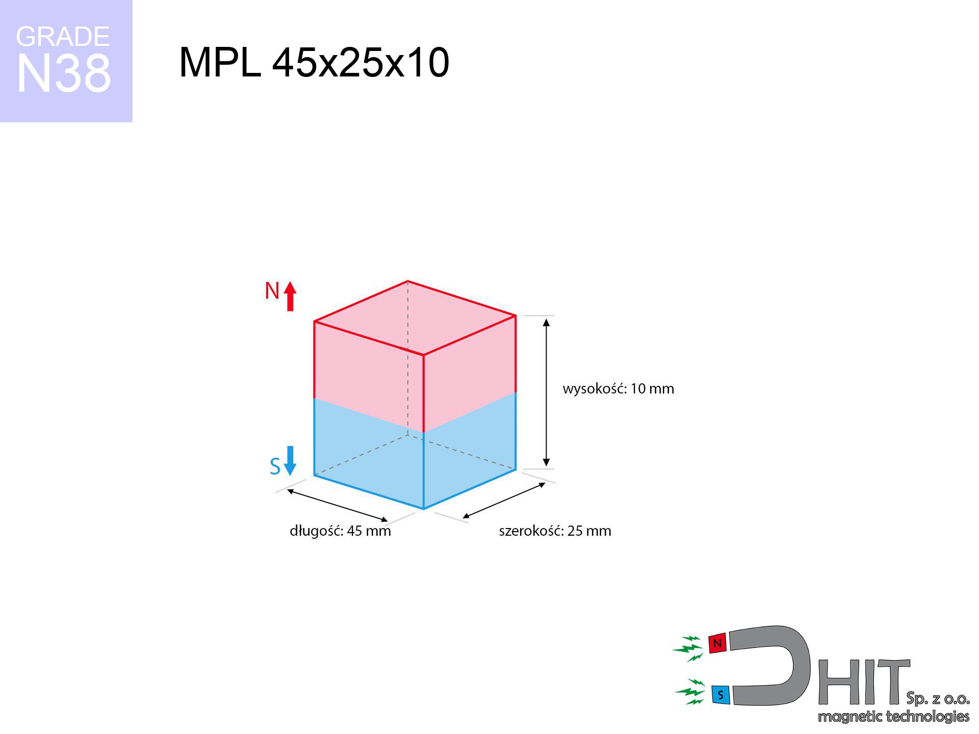
MPL 45x25x10 / N38 - lamellar magnet
lamellar magnet
Catalog no 020164
GTIN/EAN: 5906301811701
length
45 mm [±0,1 mm]
Width
25 mm [±0,1 mm]
Height
10 mm [±0,1 mm]
Weight
84.38 g
Magnetization Direction
↑ axial
Load capacity
28.48 kg / 279.40 N
Magnetic Induction
306.29 mT / 3063 Gs
Coating
[NiCuNi] Nickel
35.01 ZŁ with VAT / pcs + price for transport
28.46 ZŁ net + 23% VAT / pcs
bulk discounts:
Need more?Engineering report for this magnet
Full PDF analysis: pull and shear force, effect of distance, temperature and plate thickness, safety distances and the demagnetization curve.
Contact us by phone
+48 22 499 98 98
otherwise drop us a message through
request form
the contact section.
Strength along with form of magnetic components can be reviewed using our
modular calculator.
Orders placed before 14:00 will be shipped the same business day.
Technical parameters - MPL 45x25x10 / N38 - lamellar magnet
Specification / characteristics - MPL 45x25x10 / N38 - lamellar magnet
| properties | values |
|---|---|
| Cat. no. | 020164 |
| GTIN/EAN | 5906301811701 |
| Production/Distribution | Dhit sp. z o.o. |
| Country of origin | Poland / China / Germany |
| Customs code | 85059029 |
| length | 45 mm [±0,1 mm] |
| Width | 25 mm [±0,1 mm] |
| Height | 10 mm [±0,1 mm] |
| Weight | 84.38 g |
| Magnetization Direction | ↑ axial |
| Load capacity ~ ? | 28.48 kg / 279.40 N |
| Magnetic Induction ~ ? | 306.29 mT / 3063 Gs |
| Coating | [NiCuNi] Nickel |
| Manufacturing Tolerance | ±0.1 mm |
Magnetic properties of material N38
| properties | values | units |
|---|---|---|
| remenance Br [min. - max.] ? | 12.2-12.6 | kGs |
| remenance Br [min. - max.] ? | 1220-1260 | mT |
| coercivity bHc ? | 10.8-11.5 | kOe |
| coercivity bHc ? | 860-915 | kA/m |
| actual internal force iHc | ≥ 12 | kOe |
| actual internal force iHc | ≥ 955 | kA/m |
| energy density [min. - max.] ? | 36-38 | BH max MGOe |
| energy density [min. - max.] ? | 287-303 | BH max KJ/m |
| max. temperature ? | ≤ 80 | °C |
Physical properties of sintered neodymium magnets Nd2Fe14B at 20°C
| properties | values | units |
|---|---|---|
| Vickers hardness | ≥550 | Hv |
| Density | ≥7.4 | g/cm3 |
| Curie Temperature TC | 312 - 380 | °C |
| Curie Temperature TF | 593 - 716 | °F |
| Specific resistance | 150 | μΩ⋅cm |
| Bending strength | 250 | MPa |
| Compressive strength | 1000~1100 | MPa |
| Thermal expansion parallel (∥) to orientation (M) | (3-4) x 10-6 | °C-1 |
| Thermal expansion perpendicular (⊥) to orientation (M) | -(1-3) x 10-6 | °C-1 |
| Young's modulus | 1.7 x 10⁴ | kg/mm² |
Physical modeling of the magnet - technical parameters
Presented values represent the direct effect of a mathematical analysis. Values rely on algorithms for the material Nd2Fe14B. Operational performance might slightly differ from theoretical values. Please consider these data as a preliminary roadmap when designing systems.
Table 1: Static force (pull vs gap) - interaction chart
MPL 45x25x10 / N38
| Distance (mm) | Induction (Gauss) / mT | Pull Force (kg/lbs/g/N) | Risk Status |
|---|---|---|---|
| 0 mm |
3062 Gs
306.2 mT
|
28.48 kg / 62.79 LBS
28480.0 g / 279.4 N
|
critical level |
| 1 mm |
2918 Gs
291.8 mT
|
25.86 kg / 57.00 LBS
25856.7 g / 253.7 N
|
critical level |
| 2 mm |
2760 Gs
276.0 mT
|
23.13 kg / 51.00 LBS
23133.2 g / 226.9 N
|
critical level |
| 3 mm |
2595 Gs
259.5 mT
|
20.45 kg / 45.08 LBS
20449.5 g / 200.6 N
|
critical level |
| 5 mm |
2261 Gs
226.1 mT
|
15.53 kg / 34.23 LBS
15525.8 g / 152.3 N
|
critical level |
| 10 mm |
1529 Gs
152.9 mT
|
7.10 kg / 15.64 LBS
7096.1 g / 69.6 N
|
warning |
| 15 mm |
1018 Gs
101.8 mT
|
3.15 kg / 6.94 LBS
3147.4 g / 30.9 N
|
warning |
| 20 mm |
688 Gs
68.8 mT
|
1.44 kg / 3.17 LBS
1439.4 g / 14.1 N
|
safe |
| 30 mm |
340 Gs
34.0 mT
|
0.35 kg / 0.77 LBS
350.8 g / 3.4 N
|
safe |
| 50 mm |
111 Gs
11.1 mT
|
0.04 kg / 0.08 LBS
37.1 g / 0.4 N
|
safe |
Table 2: Shear hold (vertical surface)
MPL 45x25x10 / N38
| Distance (mm) | Friction coefficient | Pull Force (kg/lbs/g/N) |
|---|---|---|
| 0 mm | Stal (~0.2) |
5.70 kg / 12.56 LBS
5696.0 g / 55.9 N
|
| 1 mm | Stal (~0.2) |
5.17 kg / 11.40 LBS
5172.0 g / 50.7 N
|
| 2 mm | Stal (~0.2) |
4.63 kg / 10.20 LBS
4626.0 g / 45.4 N
|
| 3 mm | Stal (~0.2) |
4.09 kg / 9.02 LBS
4090.0 g / 40.1 N
|
| 5 mm | Stal (~0.2) |
3.11 kg / 6.85 LBS
3106.0 g / 30.5 N
|
| 10 mm | Stal (~0.2) |
1.42 kg / 3.13 LBS
1420.0 g / 13.9 N
|
| 15 mm | Stal (~0.2) |
0.63 kg / 1.39 LBS
630.0 g / 6.2 N
|
| 20 mm | Stal (~0.2) |
0.29 kg / 0.63 LBS
288.0 g / 2.8 N
|
| 30 mm | Stal (~0.2) |
0.07 kg / 0.15 LBS
70.0 g / 0.7 N
|
| 50 mm | Stal (~0.2) |
0.01 kg / 0.02 LBS
8.0 g / 0.1 N
|
Table 3: Wall mounting (sliding) - vertical pull
MPL 45x25x10 / N38
| Surface type | Friction coefficient / % Mocy | Max load (kg/lbs/g/N) |
|---|---|---|
| Raw steel |
µ = 0.3
30% Nominalnej Siły
|
8.54 kg / 18.84 LBS
8544.0 g / 83.8 N
|
| Painted steel (standard) |
µ = 0.2
20% Nominalnej Siły
|
5.70 kg / 12.56 LBS
5696.0 g / 55.9 N
|
| Oily/slippery steel |
µ = 0.1
10% Nominalnej Siły
|
2.85 kg / 6.28 LBS
2848.0 g / 27.9 N
|
| Magnet with anti-slip rubber |
µ = 0.5
50% Nominalnej Siły
|
14.24 kg / 31.39 LBS
14240.0 g / 139.7 N
|
Table 4: Steel thickness (saturation) - power losses
MPL 45x25x10 / N38
| Steel thickness (mm) | % power | Real pull force (kg/lbs/g/N) |
|---|---|---|
| 0.5 mm |
|
1.42 kg / 3.14 LBS
1424.0 g / 14.0 N
|
| 1 mm |
|
3.56 kg / 7.85 LBS
3560.0 g / 34.9 N
|
| 2 mm |
|
7.12 kg / 15.70 LBS
7120.0 g / 69.8 N
|
| 3 mm |
|
10.68 kg / 23.55 LBS
10680.0 g / 104.8 N
|
| 5 mm |
|
17.80 kg / 39.24 LBS
17800.0 g / 174.6 N
|
| 10 mm |
|
28.48 kg / 62.79 LBS
28480.0 g / 279.4 N
|
| 11 mm |
|
28.48 kg / 62.79 LBS
28480.0 g / 279.4 N
|
| 12 mm |
|
28.48 kg / 62.79 LBS
28480.0 g / 279.4 N
|
Table 5: Thermal resistance (stability) - thermal limit
MPL 45x25x10 / N38
| Ambient temp. (°C) | Power loss | Remaining pull (kg/lbs/g/N) | Status |
|---|---|---|---|
| 20 °C | 0.0% |
28.48 kg / 62.79 LBS
28480.0 g / 279.4 N
|
OK |
| 40 °C | -2.2% |
27.85 kg / 61.41 LBS
27853.4 g / 273.2 N
|
OK |
| 60 °C | -4.4% |
27.23 kg / 60.02 LBS
27226.9 g / 267.1 N
|
|
| 80 °C | -6.6% |
26.60 kg / 58.64 LBS
26600.3 g / 260.9 N
|
|
| 100 °C | -28.8% |
20.28 kg / 44.70 LBS
20277.8 g / 198.9 N
|
Table 6: Magnet-Magnet interaction (repulsion) - field collision
MPL 45x25x10 / N38
| Gap (mm) | Attraction (kg/lbs) (N-S) | Sliding Force (kg/lbs/g/N) | Repulsion (kg/lbs) (N-N) |
|---|---|---|---|
| 0 mm |
65.04 kg / 143.40 LBS
4 590 Gs
|
9.76 kg / 21.51 LBS
9757 g / 95.7 N
|
N/A |
| 1 mm |
62.12 kg / 136.95 LBS
5 985 Gs
|
9.32 kg / 20.54 LBS
9318 g / 91.4 N
|
55.91 kg / 123.25 LBS
~0 Gs
|
| 2 mm |
59.05 kg / 130.19 LBS
5 836 Gs
|
8.86 kg / 19.53 LBS
8858 g / 86.9 N
|
53.15 kg / 117.17 LBS
~0 Gs
|
| 3 mm |
55.95 kg / 123.34 LBS
5 680 Gs
|
8.39 kg / 18.50 LBS
8392 g / 82.3 N
|
50.35 kg / 111.01 LBS
~0 Gs
|
| 5 mm |
49.74 kg / 109.66 LBS
5 356 Gs
|
7.46 kg / 16.45 LBS
7461 g / 73.2 N
|
44.77 kg / 98.70 LBS
~0 Gs
|
| 10 mm |
35.46 kg / 78.17 LBS
4 522 Gs
|
5.32 kg / 11.73 LBS
5319 g / 52.2 N
|
31.91 kg / 70.36 LBS
~0 Gs
|
| 20 mm |
16.21 kg / 35.73 LBS
3 057 Gs
|
2.43 kg / 5.36 LBS
2431 g / 23.8 N
|
14.59 kg / 32.16 LBS
~0 Gs
|
| 50 mm |
1.58 kg / 3.48 LBS
955 Gs
|
0.24 kg / 0.52 LBS
237 g / 2.3 N
|
1.42 kg / 3.14 LBS
~0 Gs
|
| 60 mm |
0.80 kg / 1.77 LBS
680 Gs
|
0.12 kg / 0.26 LBS
120 g / 1.2 N
|
0.72 kg / 1.59 LBS
~0 Gs
|
| 70 mm |
0.43 kg / 0.94 LBS
497 Gs
|
0.06 kg / 0.14 LBS
64 g / 0.6 N
|
0.38 kg / 0.85 LBS
~0 Gs
|
| 80 mm |
0.24 kg / 0.53 LBS
372 Gs
|
0.04 kg / 0.08 LBS
36 g / 0.4 N
|
0.22 kg / 0.47 LBS
~0 Gs
|
| 90 mm |
0.14 kg / 0.31 LBS
284 Gs
|
0.02 kg / 0.05 LBS
21 g / 0.2 N
|
0.13 kg / 0.28 LBS
~0 Gs
|
| 100 mm |
0.08 kg / 0.19 LBS
221 Gs
|
0.01 kg / 0.03 LBS
13 g / 0.1 N
|
0.08 kg / 0.17 LBS
~0 Gs
|
Table 7: Safety (HSE) (electronics) - precautionary measures
MPL 45x25x10 / N38
| Object / Device | Limit (Gauss) / mT | Safe distance |
|---|---|---|
| Pacemaker | 5 Gs (0.5 mT) | 16.0 cm |
| Hearing aid | 10 Gs (1.0 mT) | 12.5 cm |
| Mechanical watch | 20 Gs (2.0 mT) | 10.0 cm |
| Phone / Smartphone | 40 Gs (4.0 mT) | 7.5 cm |
| Remote | 50 Gs (5.0 mT) | 7.0 cm |
| Payment card | 400 Gs (40.0 mT) | 3.0 cm |
| HDD hard drive | 600 Gs (60.0 mT) | 2.5 cm |
Table 8: Dynamics (kinetic energy) - warning
MPL 45x25x10 / N38
| Start from (mm) | Speed (km/h) | Energy (J) | Predicted outcome |
|---|---|---|---|
| 10 mm |
21.22 km/h
(5.89 m/s)
|
1.47 J | |
| 30 mm |
32.34 km/h
(8.98 m/s)
|
3.40 J | |
| 50 mm |
41.46 km/h
(11.52 m/s)
|
5.60 J | |
| 100 mm |
58.59 km/h
(16.28 m/s)
|
11.18 J |
Table 9: Surface protection spec
MPL 45x25x10 / N38
| Technical parameter | Value / Description |
|---|---|
| Coating type | [NiCuNi] Nickel |
| Layer structure | Nickel - Copper - Nickel |
| Layer thickness | 10-20 µm |
| Salt spray test (SST) ? | 24 h |
| Recommended environment | Indoors only (dry) |
Table 10: Electrical data (Pc)
MPL 45x25x10 / N38
| Parameter | Value | SI Unit / Description |
|---|---|---|
| Magnetic Flux | 35 829 Mx | 358.3 µWb |
| Pc Coefficient | 0.36 | Low (Flat) |
Table 11: Physics of underwater searching
MPL 45x25x10 / N38
| Environment | Effective steel pull | Effect |
|---|---|---|
| Air (land) | 28.48 kg | Standard |
| Water (riverbed) |
32.61 kg
(+4.13 kg buoyancy gain)
|
+14.5% |
1. Sliding resistance
*Note: On a vertical wall, the magnet retains only approx. 20-30% of its nominal pull.
2. Efficiency vs thickness
*Thin metal sheet (e.g. 0.5mm PC case) severely weakens the holding force.
3. Heat tolerance
*For N38 material, the safety limit is 80°C.
4. Demagnetization curve and operating point (B-H)
chart generated for the permeance coefficient Pc (Permeance Coefficient) = 0.36
The chart above illustrates the magnetic characteristics of the material within the second quadrant of the hysteresis loop. The solid red line represents the demagnetization curve (material potential), while the dashed blue line is the load line based on the magnet's geometry. The Pc (Permeance Coefficient), also known as the load line slope, is a dimensionless value that describes the relationship between the magnet's shape and its magnetic stability. The intersection of these two lines (the black dot) is the operating point — it determines the actual magnetic flux density generated by the magnet in this specific configuration. A higher Pc value means the magnet is more 'slender' (tall relative to its area), resulting in a higher operating point and better resistance to irreversible demagnetization caused by external fields or temperature. A value of 0.42 is relatively low (typical for flat magnets), meaning the operating point is closer to the 'knee' of the curve — caution is advised when operating at temperatures near the maximum limit to avoid strength loss.
Chemical composition
| iron (Fe) | 64% – 68% |
| neodymium (Nd) | 29% – 32% |
| boron (B) | 1.1% – 1.2% |
| dysprosium (Dy) | 0.5% – 2.0% |
| coating (Ni-Cu-Ni) | < 0.05% |
Environmental data
| recyclability (EoL) | 100% |
| recycled raw materials | ~10% (pre-cons) |
| carbon footprint | low / zredukowany |
| waste code (EWC) | 16 02 16 |
Check out also offers


![SM 25x350 [2xM8] / N42 - magnetic separator](https://cdn3.dhit.pl/graphics/products/sm-25x350-2xm8-pim.jpg "SM 25x350 [2xM8] / N42 - magnetic separator")
Advantages and disadvantages of Nd2Fe14B magnets.
Strengths
- Their magnetic field is durable, and after approximately 10 years it decreases only by ~1% (according to research),
- They do not lose their magnetic properties even under strong external field,
- By using a shiny layer of silver, the element acquires an elegant look,
- Magnetic induction on the top side of the magnet is impressive,
- Made from properly selected components, these magnets show impressive resistance to high heat, enabling them to function (depending on their shape) at temperatures up to 230°C and above...
- In view of the potential of flexible molding and customization to specialized solutions, NdFeB magnets can be created in a variety of geometric configurations, which amplifies use scope,
- Wide application in electronics industry – they are used in computer drives, brushless drives, medical equipment, as well as technologically advanced constructions.
- Compactness – despite small sizes they offer powerful magnetic field, making them ideal for precision applications
Weaknesses
- To avoid cracks under impact, we suggest using special steel housings. Such a solution protects the magnet and simultaneously increases its durability.
- Neodymium magnets decrease their strength under the influence of heating. As soon as 80°C is exceeded, many of them start losing their force. Therefore, we recommend our special magnets marked [AH], which maintain stability even at temperatures up to 230°C
- They rust in a humid environment. For use outdoors we recommend using waterproof magnets e.g. in rubber, plastic
- We recommend a housing - magnetic holder, due to difficulties in producing threads inside the magnet and complicated shapes.
- Health risk resulting from small fragments of magnets can be dangerous, when accidentally swallowed, which gains importance in the context of child health protection. It is also worth noting that small elements of these products can be problematic in diagnostics medical in case of swallowing.
- Higher cost of purchase is a significant factor to consider compared to ceramic magnets, especially in budget applications
Lifting parameters
Breakaway strength of the magnet in ideal conditions – what it depends on?
- on a block made of structural steel, optimally conducting the magnetic flux
- with a thickness of at least 10 mm
- characterized by even structure
- with zero gap (no coatings)
- during pulling in a direction perpendicular to the plane
- in temp. approx. 20°C
Practical aspects of lifting capacity – factors
- Distance – the presence of foreign body (paint, dirt, air) interrupts the magnetic circuit, which lowers capacity rapidly (even by 50% at 0.5 mm).
- Angle of force application – maximum parameter is obtained only during perpendicular pulling. The shear force of the magnet along the plate is usually several times lower (approx. 1/5 of the lifting capacity).
- Metal thickness – thin material does not allow full use of the magnet. Magnetic flux passes through the material instead of generating force.
- Material type – ideal substrate is high-permeability steel. Cast iron may generate lower lifting capacity.
- Surface quality – the smoother and more polished the plate, the better the adhesion and higher the lifting capacity. Roughness acts like micro-gaps.
- Thermal environment – temperature increase causes a temporary drop of induction. Check the maximum operating temperature for a given model.
Lifting capacity testing was carried out on plates with a smooth surface of optimal thickness, under a perpendicular pulling force, whereas under attempts to slide the magnet the lifting capacity is smaller. Moreover, even a slight gap between the magnet and the plate decreases the load capacity.
Safe handling of NdFeB magnets
Sensitization to coating
It is widely known that the nickel plating (the usual finish) is a potent allergen. If your skin reacts to metals, refrain from touching magnets with bare hands and select encased magnets.
Risk of cracking
Watch out for shards. Magnets can explode upon uncontrolled impact, ejecting sharp fragments into the air. We recommend safety glasses.
Danger to the youngest
Absolutely keep magnets out of reach of children. Ingestion danger is high, and the effects of magnets connecting inside the body are tragic.
Warning for heart patients
Individuals with a ICD have to maintain an safe separation from magnets. The magnetism can stop the functioning of the implant.
Conscious usage
Exercise caution. Rare earth magnets act from a long distance and connect with huge force, often quicker than you can react.
Keep away from computers
Data protection: Strong magnets can ruin payment cards and sensitive devices (heart implants, hearing aids, mechanical watches).
Crushing force
Pinching hazard: The attraction force is so great that it can result in hematomas, pinching, and even bone fractures. Use thick gloves.
Heat warning
Monitor thermal conditions. Heating the magnet above 80 degrees Celsius will permanently weaken its magnetic structure and pulling force.
Threat to navigation
Note: neodymium magnets generate a field that interferes with precision electronics. Keep a separation from your mobile, tablet, and GPS.
Fire risk
Fire warning: Rare earth powder is highly flammable. Avoid machining magnets in home conditions as this risks ignition.
Tabela kosztu i czasu dostawy
Płatność przed wysyłką:

GLS kurier
Przesyłka będzie u Ciebie za 2-3 dni
14.99 ZŁ

InPost Paczkomaty 24/7
Przesyłka będzie u Ciebie za 1-2 dni
12.30 ZŁ
Płatność przy odbiorze (pobranie):
GLS kurier
Przesyłka będzie u Ciebie za 1-2 dni
23.00 ZŁ
Rate the product
Your rating