
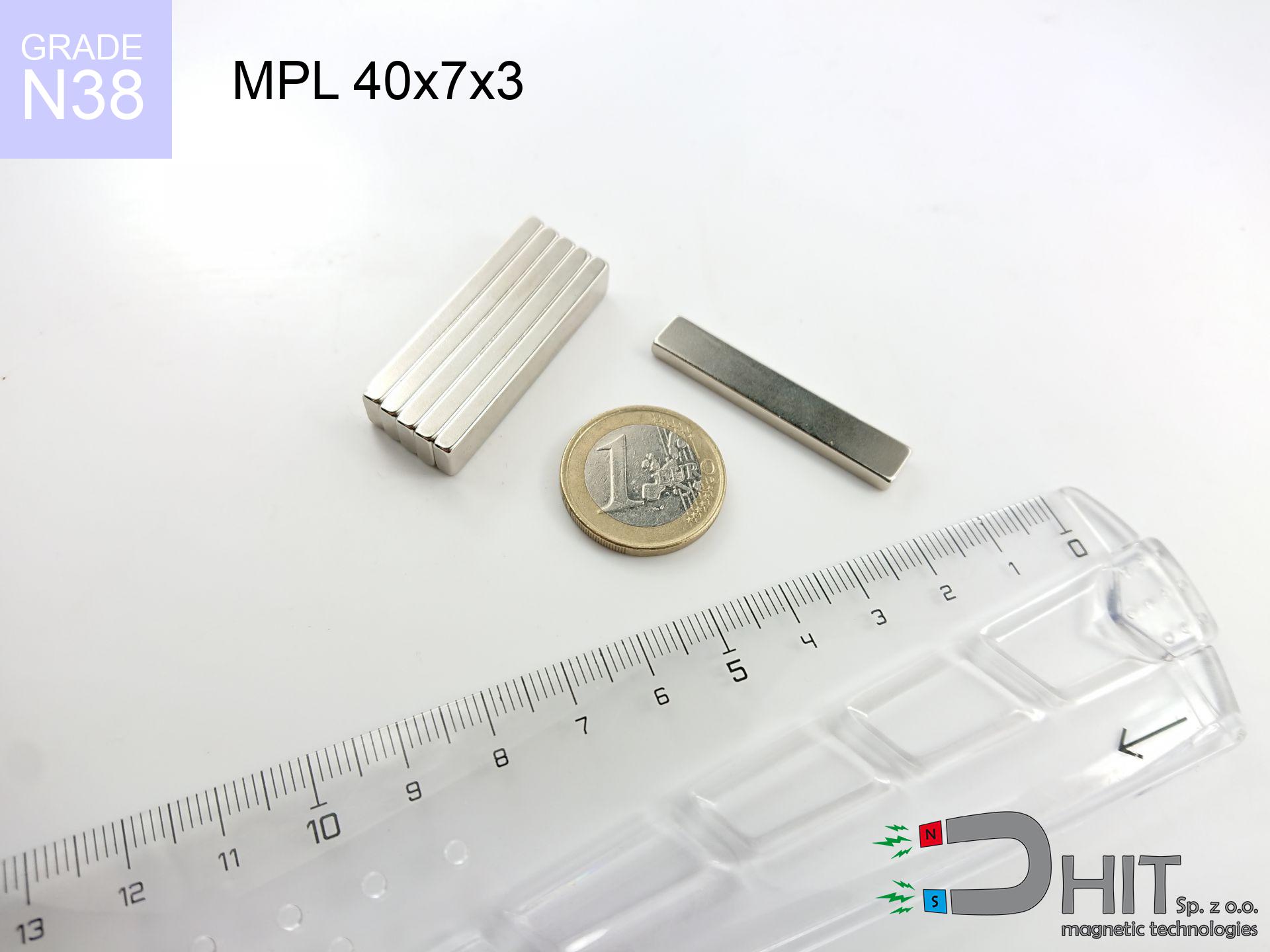

MPL 40x7x3 / N38 - lamellar magnet
lamellar magnet
Catalog no 020162
GTIN/EAN: 5906301811688
length
40 mm [±0,1 mm]
Width
7 mm [±0,1 mm]
Height
3 mm [±0,1 mm]
Weight
6.3 g
Magnetization Direction
↑ axial
Load capacity
7.14 kg / 70.02 N
Magnetic Induction
284.46 mT / 2845 Gs
Coating
[NiCuNi] Nickel
2.79 ZŁ with VAT / pcs + price for transport
2.27 ZŁ net + 23% VAT / pcs
bulk discounts:
Need more?
Give us a call
+48 22 499 98 98
otherwise send us a note using
contact form
through our site.
Force along with shape of magnets can be reviewed with our
force calculator.
Order by 14:00 and we’ll ship today!
Detailed specification - MPL 40x7x3 / N38 - lamellar magnet
Specification / characteristics - MPL 40x7x3 / N38 - lamellar magnet
| properties | values |
|---|---|
| Cat. no. | 020162 |
| GTIN/EAN | 5906301811688 |
| Production/Distribution | Dhit sp. z o.o. |
| Country of origin | Poland / China / Germany |
| Customs code | 85059029 |
| length | 40 mm [±0,1 mm] |
| Width | 7 mm [±0,1 mm] |
| Height | 3 mm [±0,1 mm] |
| Weight | 6.3 g |
| Magnetization Direction | ↑ axial |
| Load capacity ~ ? | 7.14 kg / 70.02 N |
| Magnetic Induction ~ ? | 284.46 mT / 2845 Gs |
| Coating | [NiCuNi] Nickel |
| Manufacturing Tolerance | ±0.1 mm |
Magnetic properties of material N38
| properties | values | units |
|---|---|---|
| remenance Br [min. - max.] ? | 12.2-12.6 | kGs |
| remenance Br [min. - max.] ? | 1220-1260 | mT |
| coercivity bHc ? | 10.8-11.5 | kOe |
| coercivity bHc ? | 860-915 | kA/m |
| actual internal force iHc | ≥ 12 | kOe |
| actual internal force iHc | ≥ 955 | kA/m |
| energy density [min. - max.] ? | 36-38 | BH max MGOe |
| energy density [min. - max.] ? | 287-303 | BH max KJ/m |
| max. temperature ? | ≤ 80 | °C |
Physical properties of sintered neodymium magnets Nd2Fe14B at 20°C
| properties | values | units |
|---|---|---|
| Vickers hardness | ≥550 | Hv |
| Density | ≥7.4 | g/cm3 |
| Curie Temperature TC | 312 - 380 | °C |
| Curie Temperature TF | 593 - 716 | °F |
| Specific resistance | 150 | μΩ⋅cm |
| Bending strength | 250 | MPa |
| Compressive strength | 1000~1100 | MPa |
| Thermal expansion parallel (∥) to orientation (M) | (3-4) x 10-6 | °C-1 |
| Thermal expansion perpendicular (⊥) to orientation (M) | -(1-3) x 10-6 | °C-1 |
| Young's modulus | 1.7 x 10⁴ | kg/mm² |
Technical modeling of the assembly - report
These data represent the result of a mathematical calculation. Values were calculated on algorithms for the material Nd2Fe14B. Operational conditions may differ from theoretical values. Use these data as a preliminary roadmap for designers.
Table 1: Static pull force (force vs gap) - characteristics
MPL 40x7x3 / N38
| Distance (mm) | Induction (Gauss) / mT | Pull Force (kg/lbs/g/N) | Risk Status |
|---|---|---|---|
| 0 mm |
2843 Gs
284.3 mT
|
7.14 kg / 15.74 lbs
7140.0 g / 70.0 N
|
medium risk |
| 1 mm |
2314 Gs
231.4 mT
|
4.73 kg / 10.43 lbs
4729.9 g / 46.4 N
|
medium risk |
| 2 mm |
1788 Gs
178.8 mT
|
2.83 kg / 6.23 lbs
2825.3 g / 27.7 N
|
medium risk |
| 3 mm |
1365 Gs
136.5 mT
|
1.65 kg / 3.63 lbs
1645.1 g / 16.1 N
|
weak grip |
| 5 mm |
824 Gs
82.4 mT
|
0.60 kg / 1.32 lbs
599.2 g / 5.9 N
|
weak grip |
| 10 mm |
317 Gs
31.7 mT
|
0.09 kg / 0.20 lbs
88.6 g / 0.9 N
|
weak grip |
| 15 mm |
160 Gs
16.0 mT
|
0.02 kg / 0.05 lbs
22.5 g / 0.2 N
|
weak grip |
| 20 mm |
92 Gs
9.2 mT
|
0.01 kg / 0.02 lbs
7.5 g / 0.1 N
|
weak grip |
| 30 mm |
38 Gs
3.8 mT
|
0.00 kg / 0.00 lbs
1.3 g / 0.0 N
|
weak grip |
| 50 mm |
11 Gs
1.1 mT
|
0.00 kg / 0.00 lbs
0.1 g / 0.0 N
|
weak grip |
Table 2: Slippage capacity (wall)
MPL 40x7x3 / N38
| Distance (mm) | Friction coefficient | Pull Force (kg/lbs/g/N) |
|---|---|---|
| 0 mm | Stal (~0.2) |
1.43 kg / 3.15 lbs
1428.0 g / 14.0 N
|
| 1 mm | Stal (~0.2) |
0.95 kg / 2.09 lbs
946.0 g / 9.3 N
|
| 2 mm | Stal (~0.2) |
0.57 kg / 1.25 lbs
566.0 g / 5.6 N
|
| 3 mm | Stal (~0.2) |
0.33 kg / 0.73 lbs
330.0 g / 3.2 N
|
| 5 mm | Stal (~0.2) |
0.12 kg / 0.26 lbs
120.0 g / 1.2 N
|
| 10 mm | Stal (~0.2) |
0.02 kg / 0.04 lbs
18.0 g / 0.2 N
|
| 15 mm | Stal (~0.2) |
0.00 kg / 0.01 lbs
4.0 g / 0.0 N
|
| 20 mm | Stal (~0.2) |
0.00 kg / 0.00 lbs
2.0 g / 0.0 N
|
| 30 mm | Stal (~0.2) |
0.00 kg / 0.00 lbs
0.0 g / 0.0 N
|
| 50 mm | Stal (~0.2) |
0.00 kg / 0.00 lbs
0.0 g / 0.0 N
|
Table 3: Wall mounting (sliding) - vertical pull
MPL 40x7x3 / N38
| Surface type | Friction coefficient / % Mocy | Max load (kg/lbs/g/N) |
|---|---|---|
| Raw steel |
µ = 0.3
30% Nominalnej Siły
|
2.14 kg / 4.72 lbs
2142.0 g / 21.0 N
|
| Painted steel (standard) |
µ = 0.2
20% Nominalnej Siły
|
1.43 kg / 3.15 lbs
1428.0 g / 14.0 N
|
| Oily/slippery steel |
µ = 0.1
10% Nominalnej Siły
|
0.71 kg / 1.57 lbs
714.0 g / 7.0 N
|
| Magnet with anti-slip rubber |
µ = 0.5
50% Nominalnej Siły
|
3.57 kg / 7.87 lbs
3570.0 g / 35.0 N
|
Table 4: Steel thickness (substrate influence) - power losses
MPL 40x7x3 / N38
| Steel thickness (mm) | % power | Real pull force (kg/lbs/g/N) |
|---|---|---|
| 0.5 mm |
|
0.71 kg / 1.57 lbs
714.0 g / 7.0 N
|
| 1 mm |
|
1.79 kg / 3.94 lbs
1785.0 g / 17.5 N
|
| 2 mm |
|
3.57 kg / 7.87 lbs
3570.0 g / 35.0 N
|
| 3 mm |
|
5.35 kg / 11.81 lbs
5355.0 g / 52.5 N
|
| 5 mm |
|
7.14 kg / 15.74 lbs
7140.0 g / 70.0 N
|
| 10 mm |
|
7.14 kg / 15.74 lbs
7140.0 g / 70.0 N
|
| 11 mm |
|
7.14 kg / 15.74 lbs
7140.0 g / 70.0 N
|
| 12 mm |
|
7.14 kg / 15.74 lbs
7140.0 g / 70.0 N
|
Table 5: Thermal stability (stability) - resistance threshold
MPL 40x7x3 / N38
| Ambient temp. (°C) | Power loss | Remaining pull (kg/lbs/g/N) | Status |
|---|---|---|---|
| 20 °C | 0.0% |
7.14 kg / 15.74 lbs
7140.0 g / 70.0 N
|
OK |
| 40 °C | -2.2% |
6.98 kg / 15.39 lbs
6982.9 g / 68.5 N
|
OK |
| 60 °C | -4.4% |
6.83 kg / 15.05 lbs
6825.8 g / 67.0 N
|
|
| 80 °C | -6.6% |
6.67 kg / 14.70 lbs
6668.8 g / 65.4 N
|
|
| 100 °C | -28.8% |
5.08 kg / 11.21 lbs
5083.7 g / 49.9 N
|
Table 6: Two magnets (attraction) - field range
MPL 40x7x3 / N38
| Gap (mm) | Attraction (kg/lbs) (N-S) | Shear Strength (kg/lbs/g/N) | Repulsion (kg/lbs) (N-N) |
|---|---|---|---|
| 0 mm |
13.95 kg / 30.75 lbs
4 204 Gs
|
2.09 kg / 4.61 lbs
2092 g / 20.5 N
|
N/A |
| 1 mm |
11.58 kg / 25.53 lbs
5 180 Gs
|
1.74 kg / 3.83 lbs
1737 g / 17.0 N
|
10.42 kg / 22.98 lbs
~0 Gs
|
| 2 mm |
9.24 kg / 20.37 lbs
4 628 Gs
|
1.39 kg / 3.06 lbs
1386 g / 13.6 N
|
8.32 kg / 18.34 lbs
~0 Gs
|
| 3 mm |
7.19 kg / 15.86 lbs
4 083 Gs
|
1.08 kg / 2.38 lbs
1079 g / 10.6 N
|
6.47 kg / 14.27 lbs
~0 Gs
|
| 5 mm |
4.21 kg / 9.28 lbs
3 124 Gs
|
0.63 kg / 1.39 lbs
632 g / 6.2 N
|
3.79 kg / 8.36 lbs
~0 Gs
|
| 10 mm |
1.17 kg / 2.58 lbs
1 647 Gs
|
0.18 kg / 0.39 lbs
176 g / 1.7 N
|
1.05 kg / 2.32 lbs
~0 Gs
|
| 20 mm |
0.17 kg / 0.38 lbs
633 Gs
|
0.03 kg / 0.06 lbs
26 g / 0.3 N
|
0.16 kg / 0.34 lbs
~0 Gs
|
| 50 mm |
0.01 kg / 0.01 lbs
115 Gs
|
0.00 kg / 0.00 lbs
1 g / 0.0 N
|
0.00 kg / 0.00 lbs
~0 Gs
|
| 60 mm |
0.00 kg / 0.01 lbs
76 Gs
|
0.00 kg / 0.00 lbs
0 g / 0.0 N
|
0.00 kg / 0.00 lbs
~0 Gs
|
| 70 mm |
0.00 kg / 0.00 lbs
53 Gs
|
0.00 kg / 0.00 lbs
0 g / 0.0 N
|
0.00 kg / 0.00 lbs
~0 Gs
|
| 80 mm |
0.00 kg / 0.00 lbs
38 Gs
|
0.00 kg / 0.00 lbs
0 g / 0.0 N
|
0.00 kg / 0.00 lbs
~0 Gs
|
| 90 mm |
0.00 kg / 0.00 lbs
28 Gs
|
0.00 kg / 0.00 lbs
0 g / 0.0 N
|
0.00 kg / 0.00 lbs
~0 Gs
|
| 100 mm |
0.00 kg / 0.00 lbs
21 Gs
|
0.00 kg / 0.00 lbs
0 g / 0.0 N
|
0.00 kg / 0.00 lbs
~0 Gs
|
Table 7: Hazards (implants) - warnings
MPL 40x7x3 / N38
| Object / Device | Limit (Gauss) / mT | Safe distance |
|---|---|---|
| Pacemaker | 5 Gs (0.5 mT) | 7.0 cm |
| Hearing aid | 10 Gs (1.0 mT) | 5.5 cm |
| Mechanical watch | 20 Gs (2.0 mT) | 4.0 cm |
| Phone / Smartphone | 40 Gs (4.0 mT) | 3.0 cm |
| Car key | 50 Gs (5.0 mT) | 3.0 cm |
| Payment card | 400 Gs (40.0 mT) | 1.0 cm |
| HDD hard drive | 600 Gs (60.0 mT) | 1.0 cm |
Table 8: Collisions (kinetic energy) - collision effects
MPL 40x7x3 / N38
| Start from (mm) | Speed (km/h) | Energy (J) | Predicted outcome |
|---|---|---|---|
| 10 mm |
34.21 km/h
(9.50 m/s)
|
0.28 J | |
| 30 mm |
58.81 km/h
(16.34 m/s)
|
0.84 J | |
| 50 mm |
75.92 km/h
(21.09 m/s)
|
1.40 J | |
| 100 mm |
107.36 km/h
(29.82 m/s)
|
2.80 J |
Table 9: Corrosion resistance
MPL 40x7x3 / N38
| Technical parameter | Value / Description |
|---|---|
| Coating type | [NiCuNi] Nickel |
| Layer structure | Nickel - Copper - Nickel |
| Layer thickness | 10-20 µm |
| Salt spray test (SST) ? | 24 h |
| Recommended environment | Indoors only (dry) |
Table 10: Electrical data (Pc)
MPL 40x7x3 / N38
| Parameter | Value | SI Unit / Description |
|---|---|---|
| Magnetic Flux | 6 379 Mx | 63.8 µWb |
| Pc Coefficient | 0.24 | Low (Flat) |
Table 11: Hydrostatics and buoyancy
MPL 40x7x3 / N38
| Environment | Effective steel pull | Effect |
|---|---|---|
| Air (land) | 7.14 kg | Standard |
| Water (riverbed) |
8.18 kg
(+1.04 kg buoyancy gain)
|
+14.5% |
1. Vertical hold
*Note: On a vertical surface, the magnet retains merely ~20% of its perpendicular strength.
2. Plate thickness effect
*Thin metal sheet (e.g. computer case) severely weakens the holding force.
3. Heat tolerance
*For standard magnets, the safety limit is 80°C.
4. Demagnetization curve and operating point (B-H)
chart generated for the permeance coefficient Pc (Permeance Coefficient) = 0.24
The chart above illustrates the magnetic characteristics of the material within the second quadrant of the hysteresis loop. The solid red line represents the demagnetization curve (material potential), while the dashed blue line is the load line based on the magnet's geometry. The Pc (Permeance Coefficient), also known as the load line slope, is a dimensionless value that describes the relationship between the magnet's shape and its magnetic stability. The intersection of these two lines (the black dot) is the operating point — it determines the actual magnetic flux density generated by the magnet in this specific configuration. A higher Pc value means the magnet is more 'slender' (tall relative to its area), resulting in a higher operating point and better resistance to irreversible demagnetization caused by external fields or temperature. A value of 0.42 is relatively low (typical for flat magnets), meaning the operating point is closer to the 'knee' of the curve — caution is advised when operating at temperatures near the maximum limit to avoid strength loss.
Chemical composition
| iron (Fe) | 64% – 68% |
| neodymium (Nd) | 29% – 32% |
| boron (B) | 1.1% – 1.2% |
| dysprosium (Dy) | 0.5% – 2.0% |
| coating (Ni-Cu-Ni) | < 0.05% |
Ecology and recycling (GPSR)
| recyclability (EoL) | 100% |
| recycled raw materials | ~10% (pre-cons) |
| carbon footprint | low / zredukowany |
| waste code (EWC) | 16 02 16 |
Other offers


Strengths and weaknesses of neodymium magnets.
Strengths
- They virtually do not lose strength, because even after 10 years the decline in efficiency is only ~1% (based on calculations),
- Magnets effectively resist against demagnetization caused by external fields,
- Thanks to the shiny finish, the layer of Ni-Cu-Ni, gold-plated, or silver gives an modern appearance,
- The surface of neodymium magnets generates a intense magnetic field – this is one of their assets,
- Thanks to resistance to high temperature, they are capable of working (depending on the shape) even at temperatures up to 230°C and higher...
- In view of the ability of accurate molding and adaptation to individualized solutions, NdFeB magnets can be created in a wide range of geometric configurations, which increases their versatility,
- Versatile presence in future technologies – they find application in data components, electric drive systems, medical equipment, and other advanced devices.
- Relatively small size with high pulling force – neodymium magnets offer high power in compact dimensions, which allows their use in small systems
Disadvantages
- Susceptibility to cracking is one of their disadvantages. Upon strong impact they can break. We recommend keeping them in a steel housing, which not only protects them against impacts but also increases their durability
- When exposed to high temperature, neodymium magnets experience a drop in force. Often, when the temperature exceeds 80°C, their strength decreases (depending on the size, as well as shape of the magnet). For those who need magnets for extreme conditions, we offer [AH] versions withstanding up to 230°C
- They rust in a humid environment - during use outdoors we suggest using waterproof magnets e.g. in rubber, plastic
- Due to limitations in creating threads and complex forms in magnets, we recommend using a housing - magnetic mount.
- Possible danger to health – tiny shards of magnets can be dangerous, if swallowed, which is particularly important in the aspect of protecting the youngest. Additionally, small components of these devices are able to be problematic in diagnostics medical when they are in the body.
- High unit price – neodymium magnets cost more than other types of magnets (e.g. ferrite), which hinders application in large quantities
Pull force analysis
Maximum lifting capacity of the magnet – what it depends on?
- on a plate made of mild steel, effectively closing the magnetic flux
- with a cross-section no less than 10 mm
- characterized by smoothness
- under conditions of gap-free contact (surface-to-surface)
- during detachment in a direction vertical to the plane
- in temp. approx. 20°C
Impact of factors on magnetic holding capacity in practice
- Space between surfaces – every millimeter of separation (caused e.g. by veneer or unevenness) diminishes the pulling force, often by half at just 0.5 mm.
- Loading method – declared lifting capacity refers to detachment vertically. When applying parallel force, the magnet holds much less (typically approx. 20-30% of maximum force).
- Plate thickness – insufficiently thick plate does not accept the full field, causing part of the flux to be escaped into the air.
- Material composition – different alloys attracts identically. High carbon content weaken the attraction effect.
- Smoothness – ideal contact is possible only on polished steel. Rough texture create air cushions, reducing force.
- Temperature – heating the magnet causes a temporary drop of force. Check the maximum operating temperature for a given model.
Lifting capacity was measured using a smooth steel plate of suitable thickness (min. 20 mm), under perpendicular pulling force, in contrast under parallel forces the load capacity is reduced by as much as 5 times. Additionally, even a minimal clearance between the magnet and the plate decreases the holding force.
Precautions when working with neodymium magnets
Implant safety
Individuals with a heart stimulator should maintain an safe separation from magnets. The magnetism can disrupt the operation of the life-saving device.
Heat warning
Monitor thermal conditions. Exposing the magnet above 80 degrees Celsius will destroy its magnetic structure and strength.
Metal Allergy
Some people experience a hypersensitivity to Ni, which is the common plating for neodymium magnets. Frequent touching may cause dermatitis. We recommend wear protective gloves.
Eye protection
NdFeB magnets are sintered ceramics, meaning they are very brittle. Collision of two magnets will cause them cracking into small pieces.
Keep away from children
Only for adults. Tiny parts can be swallowed, causing intestinal necrosis. Keep away from children and animals.
Compass and GPS
GPS units and smartphones are highly susceptible to magnetism. Direct contact with a strong magnet can ruin the internal compass in your phone.
Conscious usage
Handle with care. Neodymium magnets attract from a distance and snap with huge force, often faster than you can react.
Combustion hazard
Machining of NdFeB material carries a risk of fire hazard. Magnetic powder reacts violently with oxygen and is hard to extinguish.
Protect data
Very strong magnetic fields can corrupt files on payment cards, HDDs, and other magnetic media. Stay away of min. 10 cm.
Bodily injuries
Large magnets can break fingers in a fraction of a second. Under no circumstances put your hand betwixt two strong magnets.
Tabela kosztu i czasu dostawy
Płatność przed wysyłką:

GLS kurier
Przesyłka będzie u Ciebie za 2-3 dni
14.99 ZŁ

InPost Paczkomaty 24/7
Przesyłka będzie u Ciebie za 1-2 dni
12.30 ZŁ
Płatność przy odbiorze (pobranie):
GLS kurier
Przesyłka będzie u Ciebie za 1-2 dni
23.00 ZŁ
Rate the product
Your rating