
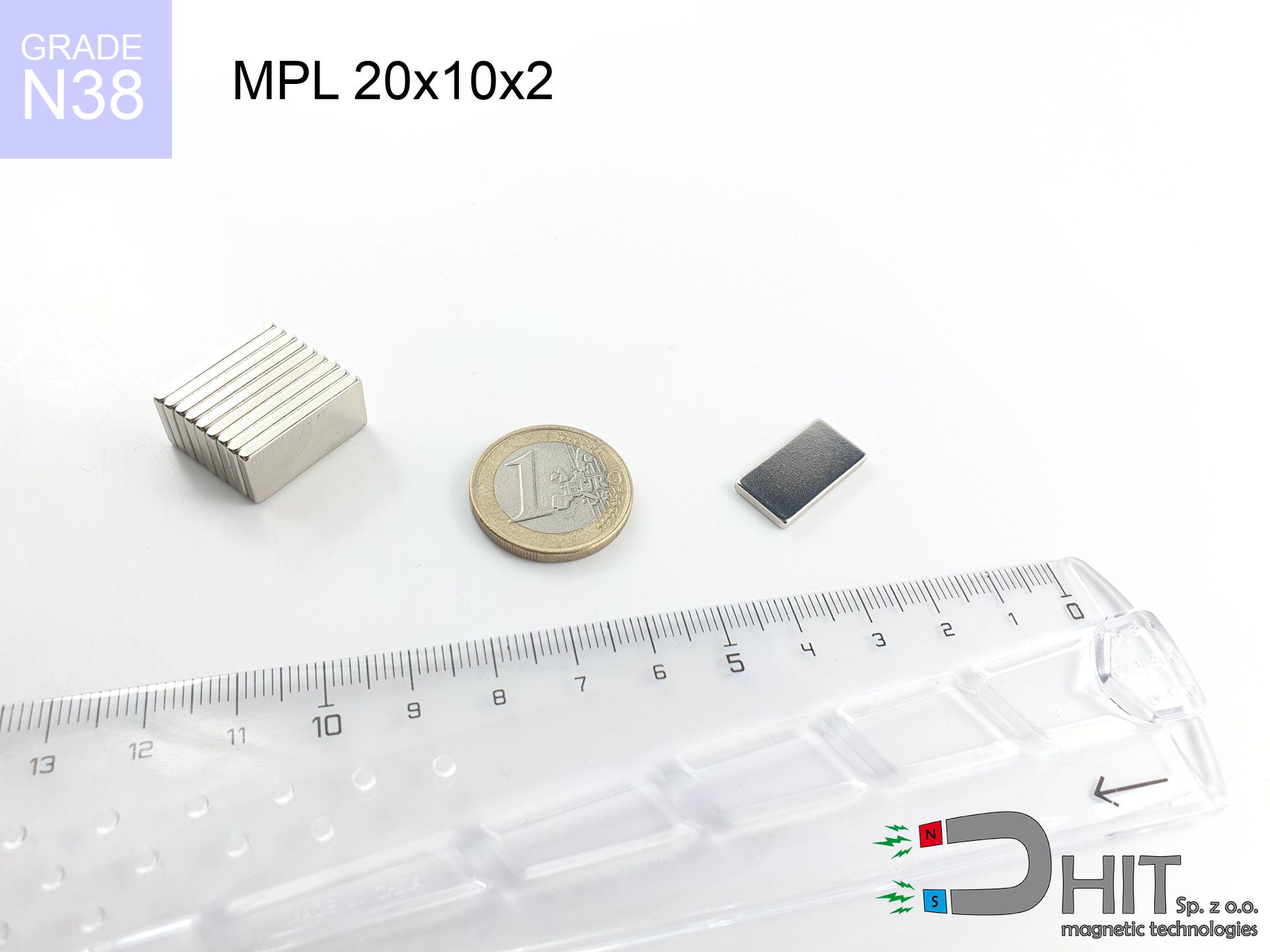
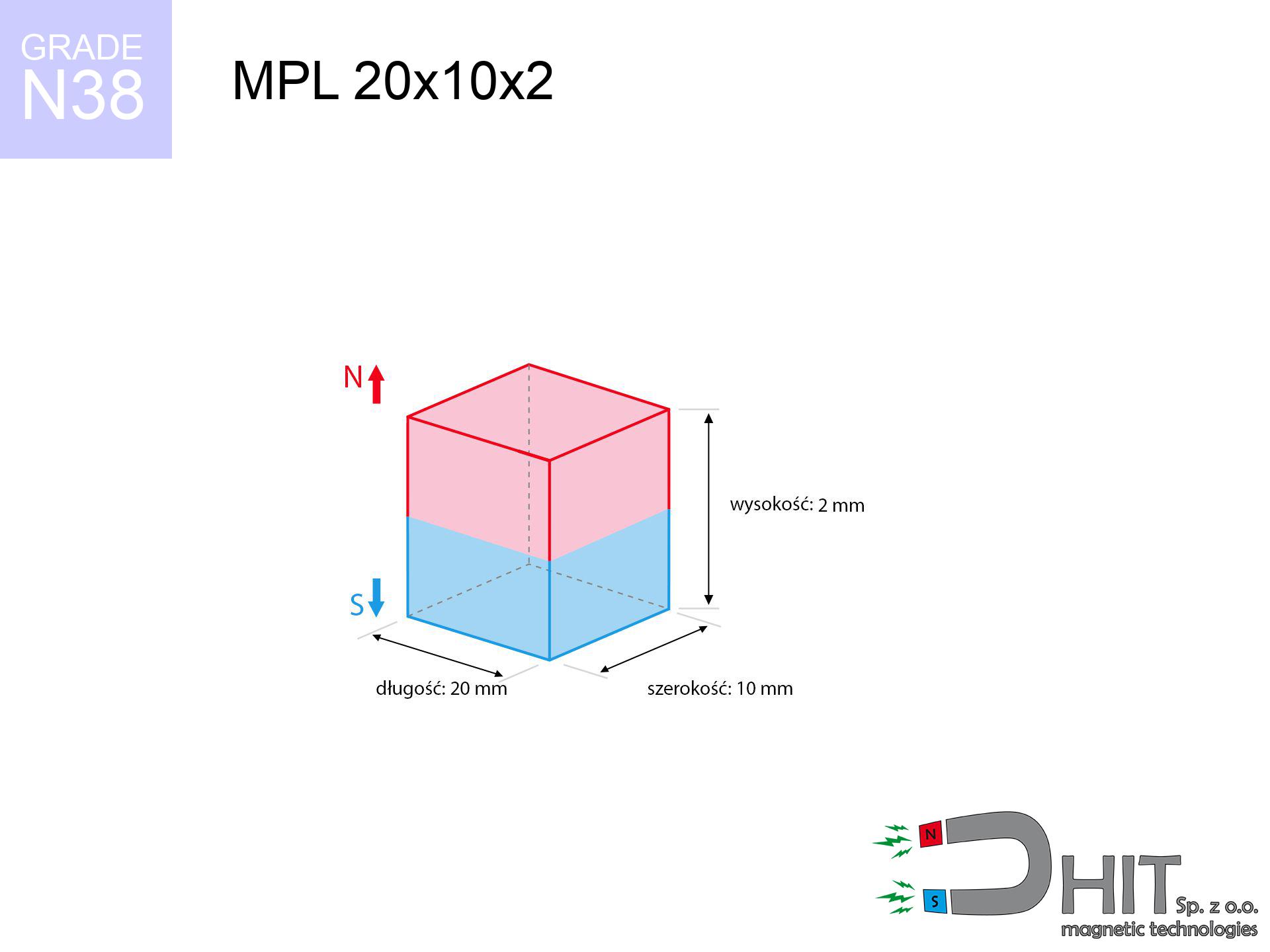
MPL 20x10x2 / N38 - lamellar magnet
lamellar magnet
Catalog no 020127
GTIN/EAN: 5906301811336
length
20 mm [±0,1 mm]
Width
10 mm [±0,1 mm]
Height
2 mm [±0,1 mm]
Weight
3 g
Magnetization Direction
↑ axial
Load capacity
1.88 kg / 18.44 N
Magnetic Induction
168.24 mT / 1682 Gs
Coating
[NiCuNi] Nickel
1.538 ZŁ with VAT / pcs + price for transport
1.250 ZŁ net + 23% VAT / pcs
bulk discounts:
Need more?Engineering report for this magnet
Full PDF analysis: pull and shear force, effect of distance, temperature and plate thickness, safety distances and the demagnetization curve.
Pick up the phone and ask
+48 22 499 98 98
or contact us via
form
our website.
Lifting power along with structure of a magnet can be calculated on our
power calculator.
Orders submitted before 14:00 will be dispatched today!
Technical parameters - MPL 20x10x2 / N38 - lamellar magnet
Specification / characteristics - MPL 20x10x2 / N38 - lamellar magnet
| properties | values |
|---|---|
| Cat. no. | 020127 |
| GTIN/EAN | 5906301811336 |
| Production/Distribution | Dhit sp. z o.o. |
| Country of origin | Poland / China / Germany |
| Customs code | 85059029 |
| length | 20 mm [±0,1 mm] |
| Width | 10 mm [±0,1 mm] |
| Height | 2 mm [±0,1 mm] |
| Weight | 3 g |
| Magnetization Direction | ↑ axial |
| Load capacity ~ ? | 1.88 kg / 18.44 N |
| Magnetic Induction ~ ? | 168.24 mT / 1682 Gs |
| Coating | [NiCuNi] Nickel |
| Manufacturing Tolerance | ±0.1 mm |
Magnetic properties of material N38
| properties | values | units |
|---|---|---|
| remenance Br [min. - max.] ? | 12.2-12.6 | kGs |
| remenance Br [min. - max.] ? | 1220-1260 | mT |
| coercivity bHc ? | 10.8-11.5 | kOe |
| coercivity bHc ? | 860-915 | kA/m |
| actual internal force iHc | ≥ 12 | kOe |
| actual internal force iHc | ≥ 955 | kA/m |
| energy density [min. - max.] ? | 36-38 | BH max MGOe |
| energy density [min. - max.] ? | 287-303 | BH max KJ/m |
| max. temperature ? | ≤ 80 | °C |
Physical properties of sintered neodymium magnets Nd2Fe14B at 20°C
| properties | values | units |
|---|---|---|
| Vickers hardness | ≥550 | Hv |
| Density | ≥7.4 | g/cm3 |
| Curie Temperature TC | 312 - 380 | °C |
| Curie Temperature TF | 593 - 716 | °F |
| Specific resistance | 150 | μΩ⋅cm |
| Bending strength | 250 | MPa |
| Compressive strength | 1000~1100 | MPa |
| Thermal expansion parallel (∥) to orientation (M) | (3-4) x 10-6 | °C-1 |
| Thermal expansion perpendicular (⊥) to orientation (M) | -(1-3) x 10-6 | °C-1 |
| Young's modulus | 1.7 x 10⁴ | kg/mm² |
Technical analysis of the magnet - technical parameters
The following information constitute the direct effect of a mathematical analysis. Results rely on models for the material Nd2Fe14B. Operational performance may differ. Treat these calculations as a reference point during assembly planning.
Table 1: Static force (pull vs distance) - characteristics
MPL 20x10x2 / N38
| Distance (mm) | Induction (Gauss) / mT | Pull Force (kg/lbs/g/N) | Risk Status |
|---|---|---|---|
| 0 mm |
1682 Gs
168.2 mT
|
1.88 kg / 4.14 lbs
1880.0 g / 18.4 N
|
safe |
| 1 mm |
1524 Gs
152.4 mT
|
1.54 kg / 3.40 lbs
1544.3 g / 15.1 N
|
safe |
| 2 mm |
1316 Gs
131.6 mT
|
1.15 kg / 2.54 lbs
1150.1 g / 11.3 N
|
safe |
| 3 mm |
1101 Gs
110.1 mT
|
0.81 kg / 1.78 lbs
806.0 g / 7.9 N
|
safe |
| 5 mm |
744 Gs
74.4 mT
|
0.37 kg / 0.81 lbs
367.6 g / 3.6 N
|
safe |
| 10 mm |
288 Gs
28.8 mT
|
0.06 kg / 0.12 lbs
55.1 g / 0.5 N
|
safe |
| 15 mm |
129 Gs
12.9 mT
|
0.01 kg / 0.02 lbs
11.1 g / 0.1 N
|
safe |
| 20 mm |
66 Gs
6.6 mT
|
0.00 kg / 0.01 lbs
2.9 g / 0.0 N
|
safe |
| 30 mm |
23 Gs
2.3 mT
|
0.00 kg / 0.00 lbs
0.4 g / 0.0 N
|
safe |
| 50 mm |
6 Gs
0.6 mT
|
0.00 kg / 0.00 lbs
0.0 g / 0.0 N
|
safe |
Table 2: Sliding hold (wall)
MPL 20x10x2 / N38
| Distance (mm) | Friction coefficient | Pull Force (kg/lbs/g/N) |
|---|---|---|
| 0 mm | Stal (~0.2) |
0.38 kg / 0.83 lbs
376.0 g / 3.7 N
|
| 1 mm | Stal (~0.2) |
0.31 kg / 0.68 lbs
308.0 g / 3.0 N
|
| 2 mm | Stal (~0.2) |
0.23 kg / 0.51 lbs
230.0 g / 2.3 N
|
| 3 mm | Stal (~0.2) |
0.16 kg / 0.36 lbs
162.0 g / 1.6 N
|
| 5 mm | Stal (~0.2) |
0.07 kg / 0.16 lbs
74.0 g / 0.7 N
|
| 10 mm | Stal (~0.2) |
0.01 kg / 0.03 lbs
12.0 g / 0.1 N
|
| 15 mm | Stal (~0.2) |
0.00 kg / 0.00 lbs
2.0 g / 0.0 N
|
| 20 mm | Stal (~0.2) |
0.00 kg / 0.00 lbs
0.0 g / 0.0 N
|
| 30 mm | Stal (~0.2) |
0.00 kg / 0.00 lbs
0.0 g / 0.0 N
|
| 50 mm | Stal (~0.2) |
0.00 kg / 0.00 lbs
0.0 g / 0.0 N
|
Table 3: Vertical assembly (shearing) - vertical pull
MPL 20x10x2 / N38
| Surface type | Friction coefficient / % Mocy | Max load (kg/lbs/g/N) |
|---|---|---|
| Raw steel |
µ = 0.3
30% Nominalnej Siły
|
0.56 kg / 1.24 lbs
564.0 g / 5.5 N
|
| Painted steel (standard) |
µ = 0.2
20% Nominalnej Siły
|
0.38 kg / 0.83 lbs
376.0 g / 3.7 N
|
| Oily/slippery steel |
µ = 0.1
10% Nominalnej Siły
|
0.19 kg / 0.41 lbs
188.0 g / 1.8 N
|
| Magnet with anti-slip rubber |
µ = 0.5
50% Nominalnej Siły
|
0.94 kg / 2.07 lbs
940.0 g / 9.2 N
|
Table 4: Material efficiency (substrate influence) - sheet metal selection
MPL 20x10x2 / N38
| Steel thickness (mm) | % power | Real pull force (kg/lbs/g/N) |
|---|---|---|
| 0.5 mm |
|
0.19 kg / 0.41 lbs
188.0 g / 1.8 N
|
| 1 mm |
|
0.47 kg / 1.04 lbs
470.0 g / 4.6 N
|
| 2 mm |
|
0.94 kg / 2.07 lbs
940.0 g / 9.2 N
|
| 3 mm |
|
1.41 kg / 3.11 lbs
1410.0 g / 13.8 N
|
| 5 mm |
|
1.88 kg / 4.14 lbs
1880.0 g / 18.4 N
|
| 10 mm |
|
1.88 kg / 4.14 lbs
1880.0 g / 18.4 N
|
| 11 mm |
|
1.88 kg / 4.14 lbs
1880.0 g / 18.4 N
|
| 12 mm |
|
1.88 kg / 4.14 lbs
1880.0 g / 18.4 N
|
Table 5: Working in heat (material behavior) - resistance threshold
MPL 20x10x2 / N38
| Ambient temp. (°C) | Power loss | Remaining pull (kg/lbs/g/N) | Status |
|---|---|---|---|
| 20 °C | 0.0% |
1.88 kg / 4.14 lbs
1880.0 g / 18.4 N
|
OK |
| 40 °C | -2.2% |
1.84 kg / 4.05 lbs
1838.6 g / 18.0 N
|
OK |
| 60 °C | -4.4% |
1.80 kg / 3.96 lbs
1797.3 g / 17.6 N
|
|
| 80 °C | -6.6% |
1.76 kg / 3.87 lbs
1755.9 g / 17.2 N
|
|
| 100 °C | -28.8% |
1.34 kg / 2.95 lbs
1338.6 g / 13.1 N
|
Table 6: Magnet-Magnet interaction (repulsion) - field collision
MPL 20x10x2 / N38
| Gap (mm) | Attraction (kg/lbs) (N-S) | Sliding Force (kg/lbs/g/N) | Repulsion (kg/lbs) (N-N) |
|---|---|---|---|
| 0 mm |
3.49 kg / 7.69 lbs
2 995 Gs
|
0.52 kg / 1.15 lbs
523 g / 5.1 N
|
N/A |
| 1 mm |
3.21 kg / 7.08 lbs
3 227 Gs
|
0.48 kg / 1.06 lbs
481 g / 4.7 N
|
2.89 kg / 6.37 lbs
~0 Gs
|
| 2 mm |
2.87 kg / 6.32 lbs
3 049 Gs
|
0.43 kg / 0.95 lbs
430 g / 4.2 N
|
2.58 kg / 5.69 lbs
~0 Gs
|
| 3 mm |
2.50 kg / 5.51 lbs
2 846 Gs
|
0.37 kg / 0.83 lbs
375 g / 3.7 N
|
2.25 kg / 4.95 lbs
~0 Gs
|
| 5 mm |
1.80 kg / 3.96 lbs
2 414 Gs
|
0.27 kg / 0.59 lbs
269 g / 2.6 N
|
1.62 kg / 3.56 lbs
~0 Gs
|
| 10 mm |
0.68 kg / 1.50 lbs
1 487 Gs
|
0.10 kg / 0.23 lbs
102 g / 1.0 N
|
0.61 kg / 1.35 lbs
~0 Gs
|
| 20 mm |
0.10 kg / 0.23 lbs
576 Gs
|
0.02 kg / 0.03 lbs
15 g / 0.2 N
|
0.09 kg / 0.20 lbs
~0 Gs
|
| 50 mm |
0.00 kg / 0.00 lbs
76 Gs
|
0.00 kg / 0.00 lbs
0 g / 0.0 N
|
0.00 kg / 0.00 lbs
~0 Gs
|
| 60 mm |
0.00 kg / 0.00 lbs
47 Gs
|
0.00 kg / 0.00 lbs
0 g / 0.0 N
|
0.00 kg / 0.00 lbs
~0 Gs
|
| 70 mm |
0.00 kg / 0.00 lbs
31 Gs
|
0.00 kg / 0.00 lbs
0 g / 0.0 N
|
0.00 kg / 0.00 lbs
~0 Gs
|
| 80 mm |
0.00 kg / 0.00 lbs
21 Gs
|
0.00 kg / 0.00 lbs
0 g / 0.0 N
|
0.00 kg / 0.00 lbs
~0 Gs
|
| 90 mm |
0.00 kg / 0.00 lbs
15 Gs
|
0.00 kg / 0.00 lbs
0 g / 0.0 N
|
0.00 kg / 0.00 lbs
~0 Gs
|
| 100 mm |
0.00 kg / 0.00 lbs
11 Gs
|
0.00 kg / 0.00 lbs
0 g / 0.0 N
|
0.00 kg / 0.00 lbs
~0 Gs
|
Table 7: Protective zones (implants) - warnings
MPL 20x10x2 / N38
| Object / Device | Limit (Gauss) / mT | Safe distance |
|---|---|---|
| Pacemaker | 5 Gs (0.5 mT) | 5.5 cm |
| Hearing aid | 10 Gs (1.0 mT) | 4.5 cm |
| Timepiece | 20 Gs (2.0 mT) | 3.5 cm |
| Phone / Smartphone | 40 Gs (4.0 mT) | 2.5 cm |
| Remote | 50 Gs (5.0 mT) | 2.5 cm |
| Payment card | 400 Gs (40.0 mT) | 1.0 cm |
| HDD hard drive | 600 Gs (60.0 mT) | 1.0 cm |
Table 8: Impact energy (kinetic energy) - collision effects
MPL 20x10x2 / N38
| Start from (mm) | Speed (km/h) | Energy (J) | Predicted outcome |
|---|---|---|---|
| 10 mm |
25.70 km/h
(7.14 m/s)
|
0.08 J | |
| 30 mm |
43.73 km/h
(12.15 m/s)
|
0.22 J | |
| 50 mm |
56.45 km/h
(15.68 m/s)
|
0.37 J | |
| 100 mm |
79.84 km/h
(22.18 m/s)
|
0.74 J |
Table 9: Coating parameters (durability)
MPL 20x10x2 / N38
| Technical parameter | Value / Description |
|---|---|
| Coating type | [NiCuNi] Nickel |
| Layer structure | Nickel - Copper - Nickel |
| Layer thickness | 10-20 µm |
| Salt spray test (SST) ? | 24 h |
| Recommended environment | Indoors only (dry) |
Table 10: Construction data (Flux)
MPL 20x10x2 / N38
| Parameter | Value | SI Unit / Description |
|---|---|---|
| Magnetic Flux | 3 825 Mx | 38.2 µWb |
| Pc Coefficient | 0.19 | Low (Flat) |
Table 11: Physics of underwater searching
MPL 20x10x2 / N38
| Environment | Effective steel pull | Effect |
|---|---|---|
| Air (land) | 1.88 kg | Standard |
| Water (riverbed) |
2.15 kg
(+0.27 kg buoyancy gain)
|
+14.5% |
1. Shear force
*Note: On a vertical surface, the magnet holds merely ~20% of its max power.
2. Steel saturation
*Thin metal sheet (e.g. computer case) drastically reduces the holding force.
3. Thermal stability
*For N38 grade, the safety limit is 80°C.
4. Demagnetization curve and operating point (B-H)
chart generated for the permeance coefficient Pc (Permeance Coefficient) = 0.19
This simulation demonstrates the magnetic stability of the selected magnet under specific geometric conditions. The solid red line represents the demagnetization curve (material potential), while the dashed blue line is the load line based on the magnet's geometry. The Pc (Permeance Coefficient), also known as the load line slope, is a dimensionless value that describes the relationship between the magnet's shape and its magnetic stability. The intersection of these two lines (the black dot) is the operating point — it determines the actual magnetic flux density generated by the magnet in this specific configuration. A higher Pc value means the magnet is more 'slender' (tall relative to its area), resulting in a higher operating point and better resistance to irreversible demagnetization caused by external fields or temperature. A value of 0.42 is relatively low (typical for flat magnets), meaning the operating point is closer to the 'knee' of the curve — caution is advised when operating at temperatures near the maximum limit to avoid strength loss.
Material specification
| iron (Fe) | 64% – 68% |
| neodymium (Nd) | 29% – 32% |
| boron (B) | 1.1% – 1.2% |
| dysprosium (Dy) | 0.5% – 2.0% |
| coating (Ni-Cu-Ni) | < 0.05% |
Sustainability
| recyclability (EoL) | 100% |
| recycled raw materials | ~10% (pre-cons) |
| carbon footprint | low / zredukowany |
| waste code (EWC) | 16 02 16 |
Other proposals


![UI 17.5x5 [C310] / N38 - badge holder](https://cdn3.dhit.pl/graphics/products/ui17.5x5-c310-rud.jpg "UI 17.5x5 [C310] / N38 - badge holder")

Pros as well as cons of rare earth magnets.
Pros
- They virtually do not lose strength, because even after ten years the decline in efficiency is only ~1% (according to literature),
- Magnets very well protect themselves against loss of magnetization caused by ambient magnetic noise,
- The use of an aesthetic layer of noble metals (nickel, gold, silver) causes the element to have aesthetics,
- The surface of neodymium magnets generates a strong magnetic field – this is a key feature,
- Thanks to resistance to high temperature, they are able to function (depending on the form) even at temperatures up to 230°C and higher...
- Possibility of precise forming as well as modifying to complex conditions,
- Wide application in future technologies – they are utilized in HDD drives, electromotive mechanisms, medical equipment, as well as multitasking production systems.
- Relatively small size with high pulling force – neodymium magnets offer high power in tiny dimensions, which makes them useful in small systems
Limitations
- To avoid cracks under impact, we recommend using special steel holders. Such a solution protects the magnet and simultaneously increases its durability.
- We warn that neodymium magnets can lose their power at high temperatures. To prevent this, we recommend our specialized [AH] magnets, which work effectively even at 230°C.
- Magnets exposed to a humid environment can corrode. Therefore when using outdoors, we advise using water-impermeable magnets made of rubber, plastic or other material protecting against moisture
- Limited possibility of making threads in the magnet and complex forms - preferred is cover - magnetic holder.
- Potential hazard resulting from small fragments of magnets can be dangerous, in case of ingestion, which gains importance in the context of child safety. Additionally, small elements of these products can disrupt the diagnostic process medical when they are in the body.
- High unit price – neodymium magnets cost more than other types of magnets (e.g. ferrite), which can limit application in large quantities
Lifting parameters
Best holding force of the magnet in ideal parameters – what it depends on?
- using a sheet made of low-carbon steel, acting as a ideal flux conductor
- whose thickness is min. 10 mm
- with a surface perfectly flat
- under conditions of no distance (surface-to-surface)
- for force acting at a right angle (in the magnet axis)
- in stable room temperature
Magnet lifting force in use – key factors
- Clearance – the presence of any layer (rust, tape, gap) acts as an insulator, which lowers capacity steeply (even by 50% at 0.5 mm).
- Loading method – declared lifting capacity refers to pulling vertically. When attempting to slide, the magnet exhibits significantly lower power (often approx. 20-30% of nominal force).
- Element thickness – for full efficiency, the steel must be sufficiently thick. Thin sheet limits the lifting capacity (the magnet "punches through" it).
- Material composition – not every steel attracts identically. Alloy additives weaken the attraction effect.
- Surface condition – ground elements ensure maximum contact, which increases field saturation. Rough surfaces reduce efficiency.
- Thermal environment – heating the magnet results in weakening of force. It is worth remembering the thermal limit for a given model.
Holding force was checked on the plate surface of 20 mm thickness, when a perpendicular force was applied, in contrast under attempts to slide the magnet the load capacity is reduced by as much as 5 times. In addition, even a minimal clearance between the magnet’s surface and the plate decreases the holding force.
Precautions when working with NdFeB magnets
Implant safety
Individuals with a pacemaker should keep an safe separation from magnets. The magnetism can interfere with the operation of the life-saving device.
Machining danger
Mechanical processing of neodymium magnets carries a risk of fire hazard. Magnetic powder reacts violently with oxygen and is hard to extinguish.
Pinching danger
Large magnets can smash fingers instantly. Do not place your hand between two attracting surfaces.
Magnetic interference
Note: neodymium magnets produce a field that disrupts sensitive sensors. Keep a separation from your mobile, tablet, and GPS.
No play value
Product intended for adults. Tiny parts can be swallowed, causing severe trauma. Store away from children and animals.
Warning for allergy sufferers
Certain individuals experience a hypersensitivity to nickel, which is the typical protective layer for neodymium magnets. Prolonged contact may cause a rash. We strongly advise wear protective gloves.
Do not overheat magnets
Keep cool. Neodymium magnets are susceptible to temperature. If you require resistance above 80°C, ask us about HT versions (H, SH, UH).
Magnet fragility
Despite the nickel coating, the material is brittle and cannot withstand shocks. Do not hit, as the magnet may crumble into hazardous fragments.
Data carriers
Device Safety: Strong magnets can ruin payment cards and sensitive devices (heart implants, hearing aids, timepieces).
Do not underestimate power
Handle magnets consciously. Their huge power can surprise even experienced users. Stay alert and respect their power.
Tabela kosztu i czasu dostawy
Płatność przed wysyłką:

GLS kurier
Przesyłka będzie u Ciebie za 2-3 dni
14.99 ZŁ

InPost Paczkomaty 24/7
Przesyłka będzie u Ciebie za 1-2 dni
12.30 ZŁ
Płatność przy odbiorze (pobranie):
GLS kurier
Przesyłka będzie u Ciebie za 1-2 dni
23.00 ZŁ
Rate the product
Your rating