
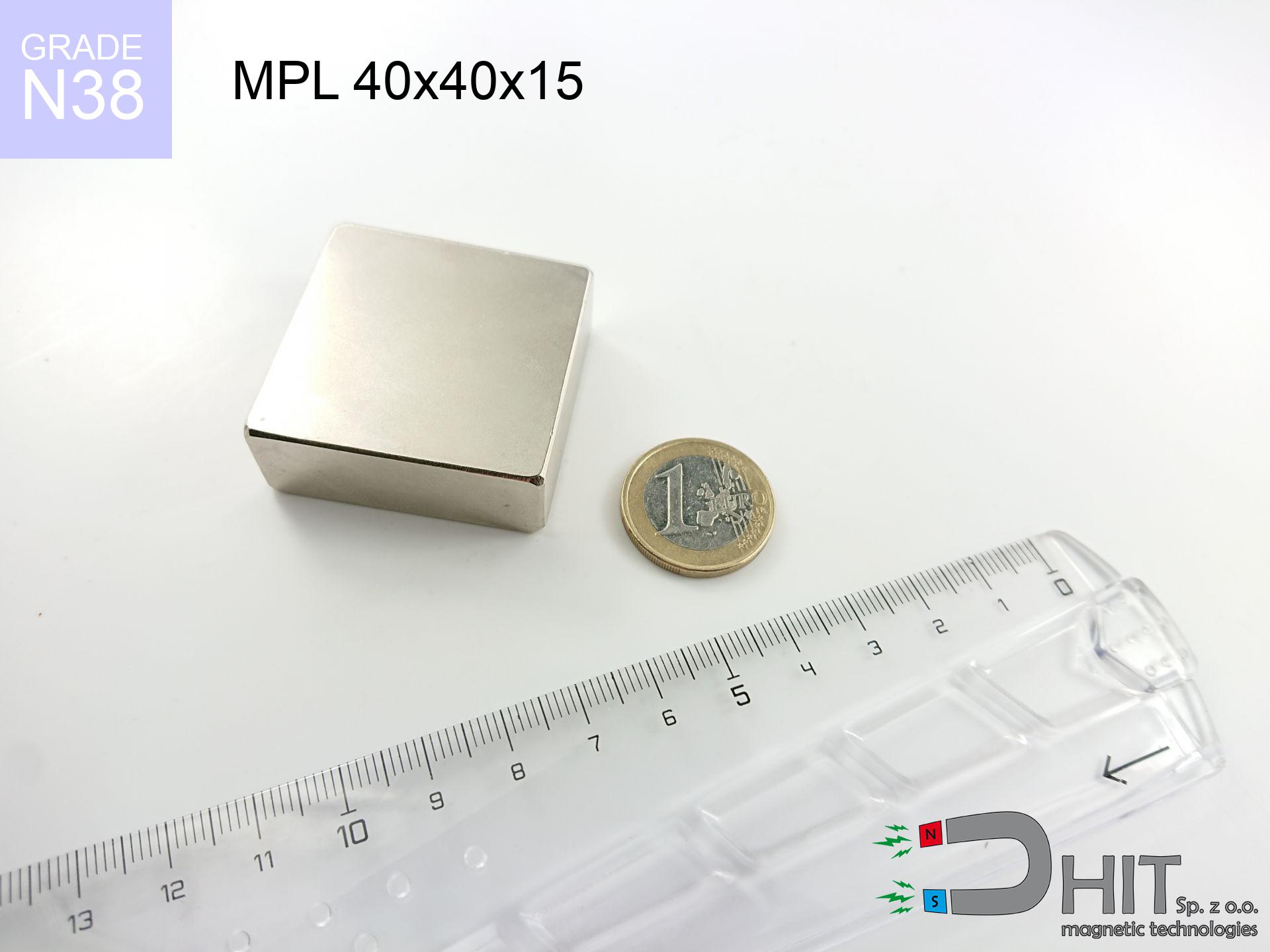
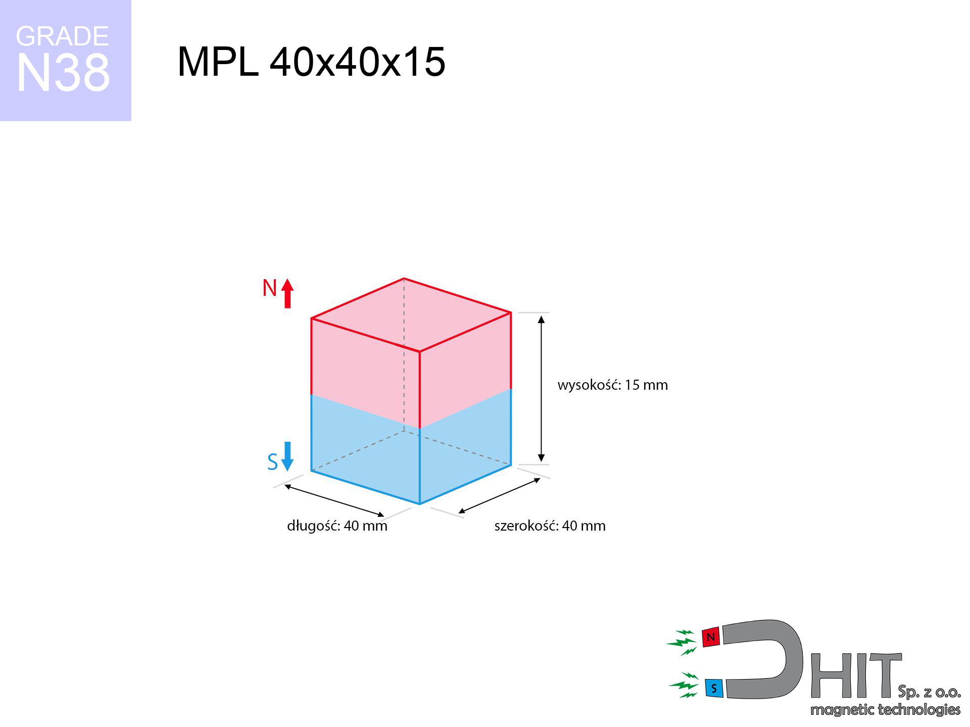
MPL 40x40x15 / N38 - lamellar magnet
lamellar magnet
Catalog no 020161
GTIN/EAN: 5906301811671
length
40 mm [±0,1 mm]
Width
40 mm [±0,1 mm]
Height
15 mm [±0,1 mm]
Weight
180 g
Magnetization Direction
↑ axial
Load capacity
46.94 kg / 460.51 N
Magnetic Induction
345.80 mT / 3458 Gs
Coating
[NiCuNi] Nickel
55.37 ZŁ with VAT / pcs + price for transport
45.02 ZŁ net + 23% VAT / pcs
bulk discounts:
Need more?
Call us now
+48 22 499 98 98
or contact us through
inquiry form
the contact section.
Specifications as well as appearance of a magnet can be verified using our
our magnetic calculator.
Orders submitted before 14:00 will be dispatched today!
Detailed specification - MPL 40x40x15 / N38 - lamellar magnet
Specification / characteristics - MPL 40x40x15 / N38 - lamellar magnet
| properties | values |
|---|---|
| Cat. no. | 020161 |
| GTIN/EAN | 5906301811671 |
| Production/Distribution | Dhit sp. z o.o. |
| Country of origin | Poland / China / Germany |
| Customs code | 85059029 |
| length | 40 mm [±0,1 mm] |
| Width | 40 mm [±0,1 mm] |
| Height | 15 mm [±0,1 mm] |
| Weight | 180 g |
| Magnetization Direction | ↑ axial |
| Load capacity ~ ? | 46.94 kg / 460.51 N |
| Magnetic Induction ~ ? | 345.80 mT / 3458 Gs |
| Coating | [NiCuNi] Nickel |
| Manufacturing Tolerance | ±0.1 mm |
Magnetic properties of material N38
| properties | values | units |
|---|---|---|
| remenance Br [min. - max.] ? | 12.2-12.6 | kGs |
| remenance Br [min. - max.] ? | 1220-1260 | mT |
| coercivity bHc ? | 10.8-11.5 | kOe |
| coercivity bHc ? | 860-915 | kA/m |
| actual internal force iHc | ≥ 12 | kOe |
| actual internal force iHc | ≥ 955 | kA/m |
| energy density [min. - max.] ? | 36-38 | BH max MGOe |
| energy density [min. - max.] ? | 287-303 | BH max KJ/m |
| max. temperature ? | ≤ 80 | °C |
Physical properties of sintered neodymium magnets Nd2Fe14B at 20°C
| properties | values | units |
|---|---|---|
| Vickers hardness | ≥550 | Hv |
| Density | ≥7.4 | g/cm3 |
| Curie Temperature TC | 312 - 380 | °C |
| Curie Temperature TF | 593 - 716 | °F |
| Specific resistance | 150 | μΩ⋅cm |
| Bending strength | 250 | MPa |
| Compressive strength | 1000~1100 | MPa |
| Thermal expansion parallel (∥) to orientation (M) | (3-4) x 10-6 | °C-1 |
| Thermal expansion perpendicular (⊥) to orientation (M) | -(1-3) x 10-6 | °C-1 |
| Young's modulus | 1.7 x 10⁴ | kg/mm² |
Technical analysis of the product - technical parameters
Presented information represent the direct effect of a engineering calculation. Results rely on models for the material Nd2Fe14B. Operational performance may differ from theoretical values. Use these calculations as a preliminary roadmap when designing systems.
Table 1: Static force (force vs distance) - power drop
MPL 40x40x15 / N38
| Distance (mm) | Induction (Gauss) / mT | Pull Force (kg/lbs/g/N) | Risk Status |
|---|---|---|---|
| 0 mm |
3458 Gs
345.8 mT
|
46.94 kg / 103.48 pounds
46940.0 g / 460.5 N
|
critical level |
| 1 mm |
3333 Gs
333.3 mT
|
43.62 kg / 96.16 pounds
43616.1 g / 427.9 N
|
critical level |
| 2 mm |
3199 Gs
319.9 mT
|
40.19 kg / 88.60 pounds
40189.1 g / 394.3 N
|
critical level |
| 3 mm |
3060 Gs
306.0 mT
|
36.77 kg / 81.06 pounds
36767.3 g / 360.7 N
|
critical level |
| 5 mm |
2773 Gs
277.3 mT
|
30.19 kg / 66.55 pounds
30187.9 g / 296.1 N
|
critical level |
| 10 mm |
2078 Gs
207.8 mT
|
16.95 kg / 37.37 pounds
16950.2 g / 166.3 N
|
critical level |
| 15 mm |
1507 Gs
150.7 mT
|
8.91 kg / 19.65 pounds
8913.7 g / 87.4 N
|
warning |
| 20 mm |
1085 Gs
108.5 mT
|
4.62 kg / 10.19 pounds
4622.3 g / 45.3 N
|
warning |
| 30 mm |
580 Gs
58.0 mT
|
1.32 kg / 2.92 pounds
1322.9 g / 13.0 N
|
low risk |
| 50 mm |
204 Gs
20.4 mT
|
0.16 kg / 0.36 pounds
164.0 g / 1.6 N
|
low risk |
Table 2: Shear force (wall)
MPL 40x40x15 / N38
| Distance (mm) | Friction coefficient | Pull Force (kg/lbs/g/N) |
|---|---|---|
| 0 mm | Stal (~0.2) |
9.39 kg / 20.70 pounds
9388.0 g / 92.1 N
|
| 1 mm | Stal (~0.2) |
8.72 kg / 19.23 pounds
8724.0 g / 85.6 N
|
| 2 mm | Stal (~0.2) |
8.04 kg / 17.72 pounds
8038.0 g / 78.9 N
|
| 3 mm | Stal (~0.2) |
7.35 kg / 16.21 pounds
7354.0 g / 72.1 N
|
| 5 mm | Stal (~0.2) |
6.04 kg / 13.31 pounds
6038.0 g / 59.2 N
|
| 10 mm | Stal (~0.2) |
3.39 kg / 7.47 pounds
3390.0 g / 33.3 N
|
| 15 mm | Stal (~0.2) |
1.78 kg / 3.93 pounds
1782.0 g / 17.5 N
|
| 20 mm | Stal (~0.2) |
0.92 kg / 2.04 pounds
924.0 g / 9.1 N
|
| 30 mm | Stal (~0.2) |
0.26 kg / 0.58 pounds
264.0 g / 2.6 N
|
| 50 mm | Stal (~0.2) |
0.03 kg / 0.07 pounds
32.0 g / 0.3 N
|
Table 3: Wall mounting (sliding) - vertical pull
MPL 40x40x15 / N38
| Surface type | Friction coefficient / % Mocy | Max load (kg/lbs/g/N) |
|---|---|---|
| Raw steel |
µ = 0.3
30% Nominalnej Siły
|
14.08 kg / 31.05 pounds
14082.0 g / 138.1 N
|
| Painted steel (standard) |
µ = 0.2
20% Nominalnej Siły
|
9.39 kg / 20.70 pounds
9388.0 g / 92.1 N
|
| Oily/slippery steel |
µ = 0.1
10% Nominalnej Siły
|
4.69 kg / 10.35 pounds
4694.0 g / 46.0 N
|
| Magnet with anti-slip rubber |
µ = 0.5
50% Nominalnej Siły
|
23.47 kg / 51.74 pounds
23470.0 g / 230.2 N
|
Table 4: Material efficiency (saturation) - power losses
MPL 40x40x15 / N38
| Steel thickness (mm) | % power | Real pull force (kg/lbs/g/N) |
|---|---|---|
| 0.5 mm |
|
2.35 kg / 5.17 pounds
2347.0 g / 23.0 N
|
| 1 mm |
|
5.87 kg / 12.94 pounds
5867.5 g / 57.6 N
|
| 2 mm |
|
11.74 kg / 25.87 pounds
11735.0 g / 115.1 N
|
| 3 mm |
|
17.60 kg / 38.81 pounds
17602.5 g / 172.7 N
|
| 5 mm |
|
29.34 kg / 64.68 pounds
29337.5 g / 287.8 N
|
| 10 mm |
|
46.94 kg / 103.48 pounds
46940.0 g / 460.5 N
|
| 11 mm |
|
46.94 kg / 103.48 pounds
46940.0 g / 460.5 N
|
| 12 mm |
|
46.94 kg / 103.48 pounds
46940.0 g / 460.5 N
|
Table 5: Thermal stability (stability) - resistance threshold
MPL 40x40x15 / N38
| Ambient temp. (°C) | Power loss | Remaining pull (kg/lbs/g/N) | Status |
|---|---|---|---|
| 20 °C | 0.0% |
46.94 kg / 103.48 pounds
46940.0 g / 460.5 N
|
OK |
| 40 °C | -2.2% |
45.91 kg / 101.21 pounds
45907.3 g / 450.4 N
|
OK |
| 60 °C | -4.4% |
44.87 kg / 98.93 pounds
44874.6 g / 440.2 N
|
|
| 80 °C | -6.6% |
43.84 kg / 96.65 pounds
43842.0 g / 430.1 N
|
|
| 100 °C | -28.8% |
33.42 kg / 73.68 pounds
33421.3 g / 327.9 N
|
Table 6: Two magnets (attraction) - forces in the system
MPL 40x40x15 / N38
| Gap (mm) | Attraction (kg/lbs) (N-S) | Sliding Force (kg/lbs/g/N) | Repulsion (kg/lbs) (N-N) |
|---|---|---|---|
| 0 mm |
117.92 kg / 259.97 pounds
4 963 Gs
|
17.69 kg / 39.00 pounds
17688 g / 173.5 N
|
N/A |
| 1 mm |
113.82 kg / 250.94 pounds
6 794 Gs
|
17.07 kg / 37.64 pounds
17074 g / 167.5 N
|
102.44 kg / 225.84 pounds
~0 Gs
|
| 2 mm |
109.57 kg / 241.57 pounds
6 666 Gs
|
16.44 kg / 36.23 pounds
16436 g / 161.2 N
|
98.62 kg / 217.41 pounds
~0 Gs
|
| 3 mm |
105.28 kg / 232.10 pounds
6 534 Gs
|
15.79 kg / 34.81 pounds
15792 g / 154.9 N
|
94.75 kg / 208.89 pounds
~0 Gs
|
| 5 mm |
96.65 kg / 213.08 pounds
6 261 Gs
|
14.50 kg / 31.96 pounds
14498 g / 142.2 N
|
86.99 kg / 191.77 pounds
~0 Gs
|
| 10 mm |
75.84 kg / 167.19 pounds
5 546 Gs
|
11.38 kg / 25.08 pounds
11376 g / 111.6 N
|
68.25 kg / 150.47 pounds
~0 Gs
|
| 20 mm |
42.58 kg / 93.88 pounds
4 155 Gs
|
6.39 kg / 14.08 pounds
6387 g / 62.7 N
|
38.32 kg / 84.49 pounds
~0 Gs
|
| 50 mm |
6.12 kg / 13.49 pounds
1 575 Gs
|
0.92 kg / 2.02 pounds
918 g / 9.0 N
|
5.51 kg / 12.14 pounds
~0 Gs
|
| 60 mm |
3.32 kg / 7.33 pounds
1 161 Gs
|
0.50 kg / 1.10 pounds
499 g / 4.9 N
|
2.99 kg / 6.59 pounds
~0 Gs
|
| 70 mm |
1.87 kg / 4.12 pounds
871 Gs
|
0.28 kg / 0.62 pounds
281 g / 2.8 N
|
1.68 kg / 3.71 pounds
~0 Gs
|
| 80 mm |
1.09 kg / 2.41 pounds
665 Gs
|
0.16 kg / 0.36 pounds
164 g / 1.6 N
|
0.98 kg / 2.17 pounds
~0 Gs
|
| 90 mm |
0.66 kg / 1.46 pounds
517 Gs
|
0.10 kg / 0.22 pounds
99 g / 1.0 N
|
0.59 kg / 1.31 pounds
~0 Gs
|
| 100 mm |
0.41 kg / 0.91 pounds
409 Gs
|
0.06 kg / 0.14 pounds
62 g / 0.6 N
|
0.37 kg / 0.82 pounds
~0 Gs
|
Table 7: Safety (HSE) (electronics) - warnings
MPL 40x40x15 / N38
| Object / Device | Limit (Gauss) / mT | Safe distance |
|---|---|---|
| Pacemaker | 5 Gs (0.5 mT) | 20.5 cm |
| Hearing aid | 10 Gs (1.0 mT) | 16.0 cm |
| Mechanical watch | 20 Gs (2.0 mT) | 12.5 cm |
| Mobile device | 40 Gs (4.0 mT) | 10.0 cm |
| Car key | 50 Gs (5.0 mT) | 9.0 cm |
| Payment card | 400 Gs (40.0 mT) | 4.0 cm |
| HDD hard drive | 600 Gs (60.0 mT) | 3.0 cm |
Table 8: Impact energy (cracking risk) - collision effects
MPL 40x40x15 / N38
| Start from (mm) | Speed (km/h) | Energy (J) | Predicted outcome |
|---|---|---|---|
| 10 mm |
19.62 km/h
(5.45 m/s)
|
2.67 J | |
| 30 mm |
28.70 km/h
(7.97 m/s)
|
5.72 J | |
| 50 mm |
36.50 km/h
(10.14 m/s)
|
9.25 J | |
| 100 mm |
51.50 km/h
(14.31 m/s)
|
18.42 J |
Table 9: Coating parameters (durability)
MPL 40x40x15 / N38
| Technical parameter | Value / Description |
|---|---|
| Coating type | [NiCuNi] Nickel |
| Layer structure | Nickel - Copper - Nickel |
| Layer thickness | 10-20 µm |
| Salt spray test (SST) ? | 24 h |
| Recommended environment | Indoors only (dry) |
Table 10: Construction data (Flux)
MPL 40x40x15 / N38
| Parameter | Value | SI Unit / Description |
|---|---|---|
| Magnetic Flux | 58 107 Mx | 581.1 µWb |
| Pc Coefficient | 0.43 | Low (Flat) |
Table 11: Physics of underwater searching
MPL 40x40x15 / N38
| Environment | Effective steel pull | Effect |
|---|---|---|
| Air (land) | 46.94 kg | Standard |
| Water (riverbed) |
53.75 kg
(+6.81 kg buoyancy gain)
|
+14.5% |
1. Shear force
*Note: On a vertical wall, the magnet retains only approx. 20-30% of its perpendicular strength.
2. Efficiency vs thickness
*Thin steel (e.g. 0.5mm PC case) significantly reduces the holding force.
3. Heat tolerance
*For standard magnets, the max working temp is 80°C.
4. Demagnetization curve and operating point (B-H)
chart generated for the permeance coefficient Pc (Permeance Coefficient) = 0.43
This simulation demonstrates the magnetic stability of the selected magnet under specific geometric conditions. The solid red line represents the demagnetization curve (material potential), while the dashed blue line is the load line based on the magnet's geometry. The Pc (Permeance Coefficient), also known as the load line slope, is a dimensionless value that describes the relationship between the magnet's shape and its magnetic stability. The intersection of these two lines (the black dot) is the operating point — it determines the actual magnetic flux density generated by the magnet in this specific configuration. A higher Pc value means the magnet is more 'slender' (tall relative to its area), resulting in a higher operating point and better resistance to irreversible demagnetization caused by external fields or temperature. A value of 0.42 is relatively low (typical for flat magnets), meaning the operating point is closer to the 'knee' of the curve — caution is advised when operating at temperatures near the maximum limit to avoid strength loss.
Chemical composition
| iron (Fe) | 64% – 68% |
| neodymium (Nd) | 29% – 32% |
| boron (B) | 1.1% – 1.2% |
| dysprosium (Dy) | 0.5% – 2.0% |
| coating (Ni-Cu-Ni) | < 0.05% |
Sustainability
| recyclability (EoL) | 100% |
| recycled raw materials | ~10% (pre-cons) |
| carbon footprint | low / zredukowany |
| waste code (EWC) | 16 02 16 |
See more offers
![SM 25x350 [2xM8] / N42 - magnetic separator](https://cdn3.dhit.pl/graphics/products/sm-25x350-2xm8-pim.jpg "SM 25x350 [2xM8] / N42 - magnetic separator")


Strengths and weaknesses of neodymium magnets.
Pros
- Their strength is maintained, and after around ten years it decreases only by ~1% (theoretically),
- Neodymium magnets are distinguished by exceptionally resistant to magnetic field loss caused by external field sources,
- The use of an shiny coating of noble metals (nickel, gold, silver) causes the element to have aesthetics,
- The surface of neodymium magnets generates a intense magnetic field – this is a distinguishing feature,
- Due to their durability and thermal resistance, neodymium magnets are capable of operate (depending on the shape) even at high temperatures reaching 230°C or more...
- Thanks to the potential of precise shaping and customization to individualized projects, neodymium magnets can be modeled in a broad palette of geometric configurations, which increases their versatility,
- Wide application in advanced technology sectors – they find application in data components, electric motors, medical equipment, also multitasking production systems.
- Thanks to concentrated force, small magnets offer high operating force, in miniature format,
Cons
- To avoid cracks upon strong impacts, we suggest using special steel housings. Such a solution secures the magnet and simultaneously increases its durability.
- When exposed to high temperature, neodymium magnets suffer a drop in force. Often, when the temperature exceeds 80°C, their power decreases (depending on the size and shape of the magnet). For those who need magnets for extreme conditions, we offer [AH] versions withstanding up to 230°C
- Magnets exposed to a humid environment can corrode. Therefore during using outdoors, we suggest using waterproof magnets made of rubber, plastic or other material resistant to moisture
- Limited ability of making threads in the magnet and complex forms - recommended is a housing - mounting mechanism.
- Possible danger related to microscopic parts of magnets can be dangerous, if swallowed, which is particularly important in the context of child health protection. It is also worth noting that tiny parts of these devices can disrupt the diagnostic process medical after entering the body.
- Higher cost of purchase is a significant factor to consider compared to ceramic magnets, especially in budget applications
Pull force analysis
Maximum lifting capacity of the magnet – what it depends on?
- with the application of a sheet made of special test steel, ensuring maximum field concentration
- whose transverse dimension is min. 10 mm
- with a plane perfectly flat
- under conditions of no distance (surface-to-surface)
- for force applied at a right angle (in the magnet axis)
- at temperature approx. 20 degrees Celsius
Lifting capacity in real conditions – factors
- Clearance – existence of any layer (paint, tape, gap) acts as an insulator, which reduces capacity rapidly (even by 50% at 0.5 mm).
- Force direction – note that the magnet has greatest strength perpendicularly. Under shear forces, the holding force drops drastically, often to levels of 20-30% of the nominal value.
- Metal thickness – the thinner the sheet, the weaker the hold. Magnetic flux penetrates through instead of generating force.
- Steel type – mild steel attracts best. Alloy admixtures reduce magnetic properties and lifting capacity.
- Smoothness – full contact is possible only on smooth steel. Rough texture reduce the real contact area, weakening the magnet.
- Operating temperature – NdFeB sinters have a negative temperature coefficient. When it is hot they are weaker, and in frost gain strength (up to a certain limit).
Holding force was checked on a smooth steel plate of 20 mm thickness, when a perpendicular force was applied, in contrast under shearing force the holding force is lower. In addition, even a slight gap between the magnet’s surface and the plate lowers the lifting capacity.
Warnings
Demagnetization risk
Control the heat. Exposing the magnet above 80 degrees Celsius will permanently weaken its properties and pulling force.
Pacemakers
Health Alert: Strong magnets can deactivate heart devices and defibrillators. Stay away if you have medical devices.
Adults only
Strictly store magnets out of reach of children. Risk of swallowing is significant, and the effects of magnets clamping inside the body are very dangerous.
Immense force
Handle with care. Rare earth magnets act from a distance and snap with massive power, often quicker than you can react.
Magnets are brittle
Neodymium magnets are sintered ceramics, meaning they are fragile like glass. Clashing of two magnets leads to them cracking into shards.
Warning for allergy sufferers
A percentage of the population experience a hypersensitivity to nickel, which is the standard coating for neodymium magnets. Extended handling can result in dermatitis. We strongly advise use protective gloves.
Hand protection
Risk of injury: The attraction force is so great that it can result in hematomas, crushing, and broken bones. Use thick gloves.
Mechanical processing
Fire warning: Rare earth powder is highly flammable. Do not process magnets in home conditions as this may cause fire.
Threat to electronics
Very strong magnetic fields can erase data on payment cards, HDDs, and other magnetic media. Maintain a gap of min. 10 cm.
Impact on smartphones
A powerful magnetic field disrupts the functioning of compasses in phones and navigation systems. Maintain magnets close to a device to avoid damaging the sensors.
Tabela kosztu i czasu dostawy
Płatność przed wysyłką:

GLS kurier
Przesyłka będzie u Ciebie za 2-3 dni
14.99 ZŁ

InPost Paczkomaty 24/7
Przesyłka będzie u Ciebie za 1-2 dni
12.30 ZŁ
Płatność przy odbiorze (pobranie):
GLS kurier
Przesyłka będzie u Ciebie za 1-2 dni
23.00 ZŁ
Rate the product
Your rating