

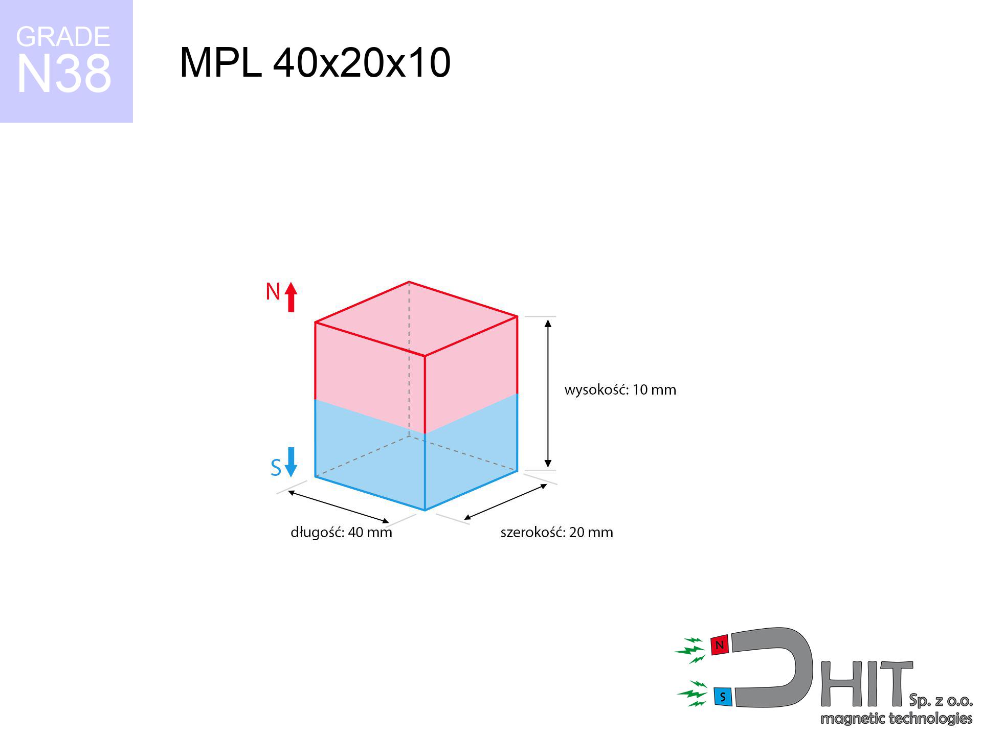
MPL 40x20x10 / N38 - lamellar magnet
lamellar magnet
Catalog no 020158
GTIN/EAN: 5906301811640
- length
- 40 mm [±0,1 mm]
- Width
- 20 mm [±0,1 mm]
- Height
- 10 mm [±0,1 mm]
- Weight
- 60 g
- Magnetization Direction
- ↑ axial
- Coating
- [NiCuNi] Nickel
31.00 zł with VAT / pcs + price for transport
25.20 zł net + 23% VAT / pcs
bulk discounts:
Need more?Engineering report for this magnet
Full PDF analysis: pull and shear force, effect of distance, temperature and plate thickness, safety distances and the demagnetization curve.
Give us a call
+48 888 99 98 98
if you prefer contact us by means of
contact form
the contact section.
Strength and form of magnets can be calculated on our
force calculator.
Orders placed before 14:00 will be shipped the same business day.
Product card - MPL 40x20x10 / N38 - lamellar magnet
Specification / characteristics - MPL 40x20x10 / N38 - lamellar magnet
| properties | values |
|---|---|
| Cat. no. | 020158 |
| GTIN/EAN | 5906301811640 |
| Production/Distribution | Dhit sp. z o.o. |
| Country of origin | Poland / China / Germany |
| Customs code | 85059029 |
| length | 40 mm [±0,1 mm] |
| Width | 20 mm [±0,1 mm] |
| Height | 10 mm [±0,1 mm] |
| Weight | 60 g |
| Magnetization Direction | ↑ axial |
| Load capacity ~ ? | 24.62 kg / 241.53 N |
| Magnetic Induction ~ ? | 349.60 mT / 3496 Gs |
| Coating | [NiCuNi] Nickel |
| Manufacturing Tolerance | ±0.1 mm |
Magnetic properties of material N38
| properties | values | units |
|---|---|---|
| remenance Br [min. - max.] ? | 12.2-12.6 | kGs |
| remenance Br [min. - max.] ? | 1220-1260 | mT |
| coercivity bHc ? | 10.8-11.5 | kOe |
| coercivity bHc ? | 860-915 | kA/m |
| actual internal force iHc | ≥ 12 | kOe |
| actual internal force iHc | ≥ 955 | kA/m |
| energy density [min. - max.] ? | 36-38 | BH max MGOe |
| energy density [min. - max.] ? | 287-303 | BH max KJ/m |
| max. temperature ? | ≤ 80 | °C |
Physical properties of sintered neodymium magnets Nd2Fe14B at 20°C
| properties | values | units |
|---|---|---|
| Vickers hardness | ≥550 | Hv |
| Density | ≥7.4 | g/cm3 |
| Curie Temperature TC | 312 - 380 | °C |
| Curie Temperature TF | 593 - 716 | °F |
| Specific resistance | 150 | μΩ⋅cm |
| Bending strength | 250 | MPa |
| Compressive strength | 1000~1100 | MPa |
| Thermal expansion parallel (∥) to orientation (M) | (3-4) x 10-6 | °C-1 |
| Thermal expansion perpendicular (⊥) to orientation (M) | -(1-3) x 10-6 | °C-1 |
| Young's modulus | 1.7 x 10⁴ | kg/mm² |
Engineering simulation of the assembly - technical parameters
These values are the direct effect of a engineering simulation. Values rely on models for the material Nd2Fe14B. Actual parameters might slightly differ. Please consider these calculations as a preliminary roadmap during assembly planning.
Table 1: Static force (force vs gap) - characteristics
MPL 40x20x10 / N38
| Distance (mm) | Induction (Gauss) / mT | Pull Force (kg/lbs/g/N) | Risk Status |
|---|---|---|---|
| 0 mm |
3495 Gs
349.5 mT
|
24.62 kg / 54.28 lbs
24620.0 g / 241.5 N
|
critical level |
| 1 mm |
3272 Gs
327.2 mT
|
21.58 kg / 47.57 lbs
21578.0 g / 211.7 N
|
critical level |
| 2 mm |
3035 Gs
303.5 mT
|
18.56 kg / 40.92 lbs
18559.3 g / 182.1 N
|
critical level |
| 3 mm |
2794 Gs
279.4 mT
|
15.73 kg / 34.69 lbs
15733.0 g / 154.3 N
|
critical level |
| 5 mm |
2332 Gs
233.2 mT
|
10.96 kg / 24.16 lbs
10959.2 g / 107.5 N
|
critical level |
| 10 mm |
1433 Gs
143.3 mT
|
4.14 kg / 9.12 lbs
4136.4 g / 40.6 N
|
strong |
| 15 mm |
891 Gs
89.1 mT
|
1.60 kg / 3.52 lbs
1598.7 g / 15.7 N
|
safe |
| 20 mm |
574 Gs
57.4 mT
|
0.66 kg / 1.46 lbs
664.0 g / 6.5 N
|
safe |
| 30 mm |
267 Gs
26.7 mT
|
0.14 kg / 0.32 lbs
143.7 g / 1.4 N
|
safe |
| 50 mm |
82 Gs
8.2 mT
|
0.01 kg / 0.03 lbs
13.7 g / 0.1 N
|
safe |
Table 2: Sliding capacity (vertical surface)
MPL 40x20x10 / N38
| Distance (mm) | Friction coefficient | Pull Force (kg/lbs/g/N) |
|---|---|---|
| 0 mm | Stal (~0.2) |
4.92 kg / 10.86 lbs
4924.0 g / 48.3 N
|
| 1 mm | Stal (~0.2) |
4.32 kg / 9.52 lbs
4316.0 g / 42.3 N
|
| 2 mm | Stal (~0.2) |
3.71 kg / 8.18 lbs
3712.0 g / 36.4 N
|
| 3 mm | Stal (~0.2) |
3.15 kg / 6.94 lbs
3146.0 g / 30.9 N
|
| 5 mm | Stal (~0.2) |
2.19 kg / 4.83 lbs
2192.0 g / 21.5 N
|
| 10 mm | Stal (~0.2) |
0.83 kg / 1.83 lbs
828.0 g / 8.1 N
|
| 15 mm | Stal (~0.2) |
0.32 kg / 0.71 lbs
320.0 g / 3.1 N
|
| 20 mm | Stal (~0.2) |
0.13 kg / 0.29 lbs
132.0 g / 1.3 N
|
| 30 mm | Stal (~0.2) |
0.03 kg / 0.06 lbs
28.0 g / 0.3 N
|
| 50 mm | Stal (~0.2) |
0.00 kg / 0.00 lbs
2.0 g / 0.0 N
|
Table 3: Wall mounting (sliding) - behavior on slippery surfaces
MPL 40x20x10 / N38
| Surface type | Friction coefficient / % Mocy | Max load (kg/lbs/g/N) |
|---|---|---|
| Raw steel |
µ = 0.3
30% Nominalnej Siły
|
7.39 kg / 16.28 lbs
7386.0 g / 72.5 N
|
| Painted steel (standard) |
µ = 0.2
20% Nominalnej Siły
|
4.92 kg / 10.86 lbs
4924.0 g / 48.3 N
|
| Oily/slippery steel |
µ = 0.1
10% Nominalnej Siły
|
2.46 kg / 5.43 lbs
2462.0 g / 24.2 N
|
| Magnet with anti-slip rubber |
µ = 0.5
50% Nominalnej Siły
|
12.31 kg / 27.14 lbs
12310.0 g / 120.8 N
|
Table 4: Steel thickness (substrate influence) - sheet metal selection
MPL 40x20x10 / N38
| Steel thickness (mm) | % power | Real pull force (kg/lbs/g/N) |
|---|---|---|
| 0.5 mm |
|
1.23 kg / 2.71 lbs
1231.0 g / 12.1 N
|
| 1 mm |
|
3.08 kg / 6.78 lbs
3077.5 g / 30.2 N
|
| 2 mm |
|
6.16 kg / 13.57 lbs
6155.0 g / 60.4 N
|
| 3 mm |
|
9.23 kg / 20.35 lbs
9232.5 g / 90.6 N
|
| 5 mm |
|
15.39 kg / 33.92 lbs
15387.5 g / 151.0 N
|
| 10 mm |
|
24.62 kg / 54.28 lbs
24620.0 g / 241.5 N
|
| 11 mm |
|
24.62 kg / 54.28 lbs
24620.0 g / 241.5 N
|
| 12 mm |
|
24.62 kg / 54.28 lbs
24620.0 g / 241.5 N
|
Table 5: Thermal stability (material behavior) - resistance threshold
MPL 40x20x10 / N38
| Ambient temp. (°C) | Power loss | Remaining pull (kg/lbs/g/N) | Status |
|---|---|---|---|
| 20 °C | 0.0% |
24.62 kg / 54.28 lbs
24620.0 g / 241.5 N
|
OK |
| 40 °C | -2.2% |
24.08 kg / 53.08 lbs
24078.4 g / 236.2 N
|
OK |
| 60 °C | -4.4% |
23.54 kg / 51.89 lbs
23536.7 g / 230.9 N
|
|
| 80 °C | -6.6% |
23.00 kg / 50.70 lbs
22995.1 g / 225.6 N
|
|
| 100 °C | -28.8% |
17.53 kg / 38.65 lbs
17529.4 g / 172.0 N
|
Table 6: Two magnets (attraction) - field collision
MPL 40x20x10 / N38
| Gap (mm) | Attraction (kg/lbs) (N-S) | Shear Strength (kg/lbs/g/N) | Repulsion (kg/lbs) (N-N) |
|---|---|---|---|
| 0 mm |
60.25 kg / 132.83 lbs
4 926 Gs
|
9.04 kg / 19.93 lbs
9038 g / 88.7 N
|
N/A |
| 1 mm |
56.58 kg / 124.73 lbs
6 774 Gs
|
8.49 kg / 18.71 lbs
8487 g / 83.3 N
|
50.92 kg / 112.26 lbs
~0 Gs
|
| 2 mm |
52.81 kg / 116.42 lbs
6 544 Gs
|
7.92 kg / 17.46 lbs
7921 g / 77.7 N
|
47.53 kg / 104.78 lbs
~0 Gs
|
| 3 mm |
49.07 kg / 108.19 lbs
6 309 Gs
|
7.36 kg / 16.23 lbs
7361 g / 72.2 N
|
44.17 kg / 97.37 lbs
~0 Gs
|
| 5 mm |
41.89 kg / 92.34 lbs
5 828 Gs
|
6.28 kg / 13.85 lbs
6283 g / 61.6 N
|
37.70 kg / 83.11 lbs
~0 Gs
|
| 10 mm |
26.82 kg / 59.13 lbs
4 664 Gs
|
4.02 kg / 8.87 lbs
4023 g / 39.5 N
|
24.14 kg / 53.22 lbs
~0 Gs
|
| 20 mm |
10.12 kg / 22.32 lbs
2 865 Gs
|
1.52 kg / 3.35 lbs
1518 g / 14.9 N
|
9.11 kg / 20.09 lbs
~0 Gs
|
| 50 mm |
0.73 kg / 1.61 lbs
769 Gs
|
0.11 kg / 0.24 lbs
109 g / 1.1 N
|
0.66 kg / 1.45 lbs
~0 Gs
|
| 60 mm |
0.35 kg / 0.78 lbs
534 Gs
|
0.05 kg / 0.12 lbs
53 g / 0.5 N
|
0.32 kg / 0.70 lbs
~0 Gs
|
| 70 mm |
0.18 kg / 0.40 lbs
383 Gs
|
0.03 kg / 0.06 lbs
27 g / 0.3 N
|
0.16 kg / 0.36 lbs
~0 Gs
|
| 80 mm |
0.10 kg / 0.22 lbs
282 Gs
|
0.01 kg / 0.03 lbs
15 g / 0.1 N
|
0.09 kg / 0.20 lbs
~0 Gs
|
| 90 mm |
0.06 kg / 0.12 lbs
214 Gs
|
0.01 kg / 0.02 lbs
8 g / 0.1 N
|
0.05 kg / 0.11 lbs
~0 Gs
|
| 100 mm |
0.03 kg / 0.07 lbs
165 Gs
|
0.01 kg / 0.01 lbs
5 g / 0.0 N
|
0.03 kg / 0.07 lbs
~0 Gs
|
Table 7: Protective zones (electronics) - warnings
MPL 40x20x10 / N38
| Object / Device | Limit (Gauss) / mT | Safe distance |
|---|---|---|
| Pacemaker | 5 Gs (0.5 mT) | 14.5 cm |
| Hearing aid | 10 Gs (1.0 mT) | 11.5 cm |
| Mechanical watch | 20 Gs (2.0 mT) | 9.0 cm |
| Phone / Smartphone | 40 Gs (4.0 mT) | 7.0 cm |
| Remote | 50 Gs (5.0 mT) | 6.5 cm |
| Payment card | 400 Gs (40.0 mT) | 2.5 cm |
| HDD hard drive | 600 Gs (60.0 mT) | 2.0 cm |
Table 8: Dynamics (kinetic energy) - warning
MPL 40x20x10 / N38
| Start from (mm) | Speed (km/h) | Energy (J) | Predicted outcome |
|---|---|---|---|
| 10 mm |
22.73 km/h
(6.32 m/s)
|
1.20 J | |
| 30 mm |
24.69 km/h
(6.86 m/s)
|
1.41 J | |
| 50 mm |
24.78 km/h
(6.88 m/s)
|
1.42 J | |
| 100 mm |
24.79 km/h
(6.89 m/s)
|
1.42 J |
Table 9: Surface protection spec
MPL 40x20x10 / N38
| Technical parameter | Value / Description |
|---|---|
| Coating type | [NiCuNi] Nickel |
| Layer structure | Nickel - Copper - Nickel |
| Layer thickness | 10-20 µm |
| Salt spray test (SST) ? | 24 h |
| Recommended environment | Indoors only (dry) |
Table 10: Construction data (Flux)
MPL 40x20x10 / N38
| Parameter | Value | SI Unit / Description |
|---|---|---|
| Magnetic Flux | 28 125 Mx | 281.2 µWb |
| Pc Coefficient | 0.42 | Low (Flat) |
Table 11: Physics of underwater searching
MPL 40x20x10 / N38
| Environment | Effective steel pull | Effect |
|---|---|---|
| Air (land) | 24.62 kg | Standard |
| Water (riverbed) |
28.19 kg
(+3.57 kg buoyancy gain)
|
+14.5% |
1. Vertical hold
*Warning: On a vertical wall, the magnet holds just approx. 20-30% of its perpendicular strength.
2. Steel saturation
*Thin steel (e.g. 0.5mm PC case) significantly weakens the holding force.
3. Temperature resistance
*For N38 material, the critical limit is 80°C.
4. Demagnetization curve and operating point (B-H)
chart generated for the permeance coefficient Pc (Permeance Coefficient) = 0.42
The chart above illustrates the magnetic characteristics of the material within the second quadrant of the hysteresis loop. The solid red line represents the demagnetization curve (material potential), while the dashed blue line is the load line based on the magnet's geometry. The Pc (Permeance Coefficient), also known as the load line slope, is a dimensionless value that describes the relationship between the magnet's shape and its magnetic stability. The intersection of these two lines (the black dot) is the operating point — it determines the actual magnetic flux density generated by the magnet in this specific configuration. A higher Pc value means the magnet is more 'slender' (tall relative to its area), resulting in a higher operating point and better resistance to irreversible demagnetization caused by external fields or temperature. A value of 0.42 is relatively low (typical for flat magnets), meaning the operating point is closer to the 'knee' of the curve — caution is advised when operating at temperatures near the maximum limit to avoid strength loss.
Elemental analysis
| iron (Fe) | 64% – 68% |
| neodymium (Nd) | 29% – 32% |
| boron (B) | 1.1% – 1.2% |
| dysprosium (Dy) | 0.5% – 2.0% |
| coating (Ni-Cu-Ni) | < 0.05% |
Sustainability
| recyclability (EoL) | 100% |
| recycled raw materials | ~10% (pre-cons) |
| carbon footprint | low / zredukowany |
| waste code (EWC) | 16 02 16 |
Other products

![SM 32x275 [2xM8] / N42 - magnetic separator](https://cdn3.dhit.pl/graphics/products/sm-32x275-2xm8-hac.jpg "SM 32x275 [2xM8] / N42 - magnetic separator")
![BM 750x180x70 [4x M8] - magnetic beam](https://cdn3.dhit.pl/graphics/products/bm-750x180x70-4x-m8-zif.jpg "BM 750x180x70 [4x M8] - magnetic beam")

Advantages and disadvantages of neodymium magnets.
Strengths
- They retain attractive force for around 10 years – the loss is just ~1% (based on simulations),
- They do not lose their magnetic properties even under strong external field,
- In other words, due to the smooth finish of nickel, the element gains visual value,
- Magnetic induction on the surface of the magnet is exceptional,
- Thanks to resistance to high temperature, they are capable of working (depending on the shape) even at temperatures up to 230°C and higher...
- Possibility of exact modeling and adapting to precise requirements,
- Huge importance in advanced technology sectors – they find application in mass storage devices, brushless drives, precision medical tools, also modern systems.
- Thanks to efficiency per cm³, small magnets offer high operating force, with minimal size,
Limitations
- They are fragile upon heavy impacts. To avoid cracks, it is worth securing magnets using a steel holder. Such protection not only protects the magnet but also increases its resistance to damage
- Neodymium magnets lose their power under the influence of heating. As soon as 80°C is exceeded, many of them start losing their power. Therefore, we recommend our special magnets marked [AH], which maintain stability even at temperatures up to 230°C
- Due to the susceptibility of magnets to corrosion in a humid environment, we advise using waterproof magnets made of rubber, plastic or other material resistant to moisture, in case of application outdoors
- Due to limitations in creating nuts and complex forms in magnets, we recommend using cover - magnetic mechanism.
- Health risk related to microscopic parts of magnets are risky, in case of ingestion, which gains importance in the aspect of protecting the youngest. Additionally, small elements of these devices can disrupt the diagnostic process medical in case of swallowing.
- Higher cost of purchase is a significant factor to consider compared to ceramic magnets, especially in budget applications
Pull force analysis
Optimal lifting capacity of a neodymium magnet – what affects it?
- using a plate made of low-carbon steel, functioning as a circuit closing element
- whose transverse dimension equals approx. 10 mm
- characterized by even structure
- with zero gap (without paint)
- under perpendicular force vector (90-degree angle)
- at temperature approx. 20 degrees Celsius
Practical aspects of lifting capacity – factors
- Gap between magnet and steel – every millimeter of distance (caused e.g. by varnish or dirt) drastically reduces the pulling force, often by half at just 0.5 mm.
- Angle of force application – maximum parameter is obtained only during perpendicular pulling. The shear force of the magnet along the surface is usually many times lower (approx. 1/5 of the lifting capacity).
- Plate thickness – too thin steel causes magnetic saturation, causing part of the flux to be wasted into the air.
- Plate material – mild steel attracts best. Alloy steels lower magnetic properties and lifting capacity.
- Surface quality – the smoother and more polished the surface, the better the adhesion and higher the lifting capacity. Roughness acts like micro-gaps.
- Heat – neodymium magnets have a negative temperature coefficient. At higher temperatures they lose power, and at low temperatures they can be stronger (up to a certain limit).
Lifting capacity was determined with the use of a polished steel plate of suitable thickness (min. 20 mm), under perpendicular pulling force, in contrast under shearing force the load capacity is reduced by as much as 5 times. Additionally, even a slight gap between the magnet and the plate lowers the load capacity.
Safe handling of neodymium magnets
Dust is flammable
Powder generated during machining of magnets is self-igniting. Avoid drilling into magnets without proper cooling and knowledge.
Impact on smartphones
A powerful magnetic field negatively affects the functioning of compasses in smartphones and navigation systems. Maintain magnets close to a device to prevent damaging the sensors.
Do not give to children
Product intended for adults. Small elements can be swallowed, causing serious injuries. Store out of reach of children and animals.
Safe operation
Before use, read the rules. Sudden snapping can destroy the magnet or hurt your hand. Be predictive.
Physical harm
Watch your fingers. Two large magnets will join instantly with a force of several hundred kilograms, destroying anything in their path. Be careful!
Do not overheat magnets
Watch the temperature. Exposing the magnet to high heat will permanently weaken its properties and pulling force.
Keep away from computers
Data protection: Neodymium magnets can damage data carriers and delicate electronics (pacemakers, medical aids, timepieces).
Life threat
People with a pacemaker must maintain an absolute distance from magnets. The magnetism can disrupt the functioning of the implant.
Allergic reactions
Studies show that nickel (the usual finish) is a potent allergen. If you have an allergy, refrain from touching magnets with bare hands or select encased magnets.
Fragile material
Despite metallic appearance, neodymium is brittle and not impact-resistant. Avoid impacts, as the magnet may crumble into sharp, dangerous pieces.
Tabela kosztu i czasu dostawy
Płatność przed wysyłką:

GLS kurier
Przesyłka będzie u Ciebie za 2-3 dni
14.99 ZŁ

InPost Paczkomaty 24/7
Przesyłka będzie u Ciebie za 1-2 dni
12.30 ZŁ
Płatność przy odbiorze (pobranie):
GLS kurier
Przesyłka będzie u Ciebie za 1-2 dni
23.00 ZŁ
Rate the product
Your rating