
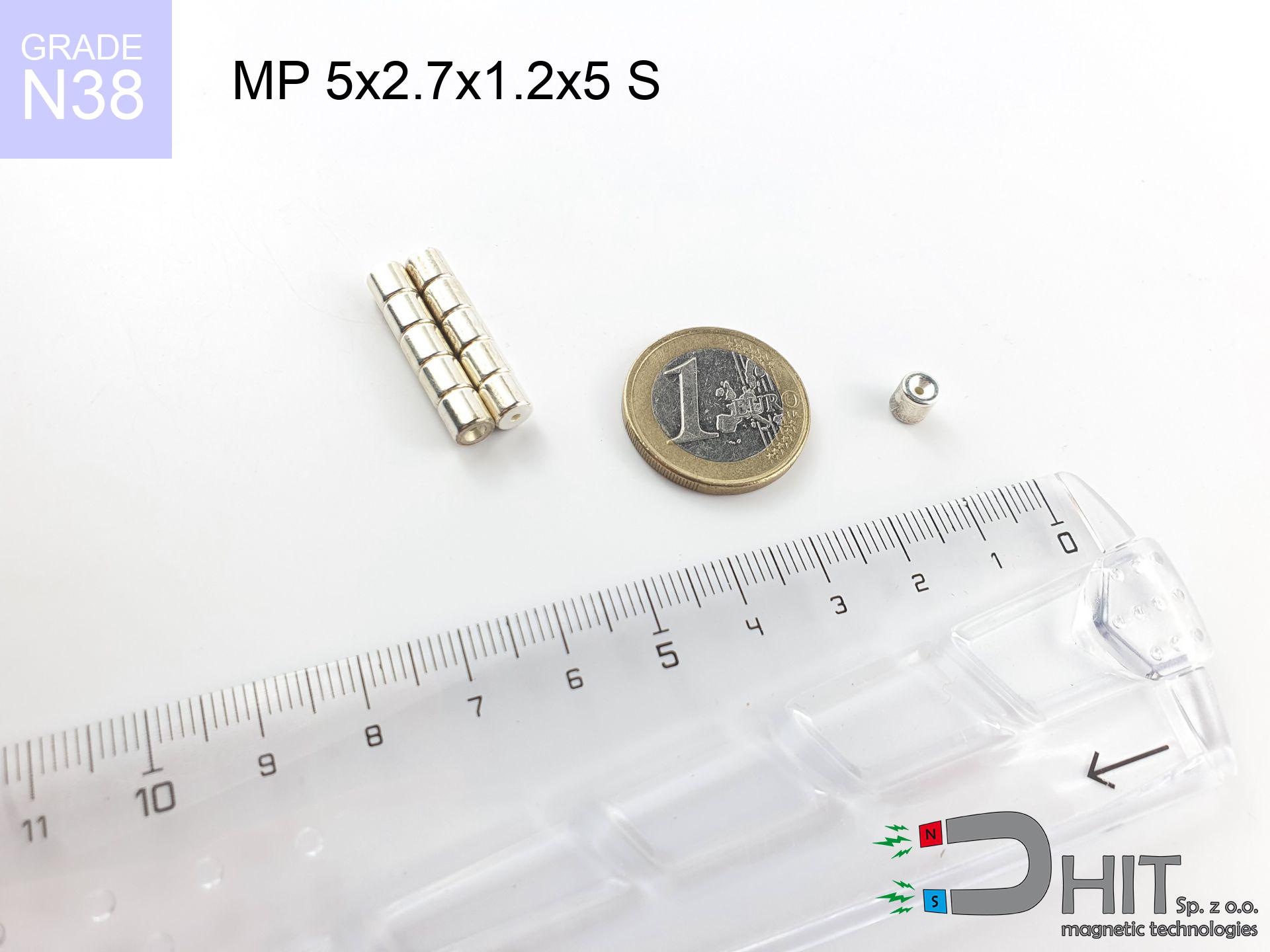
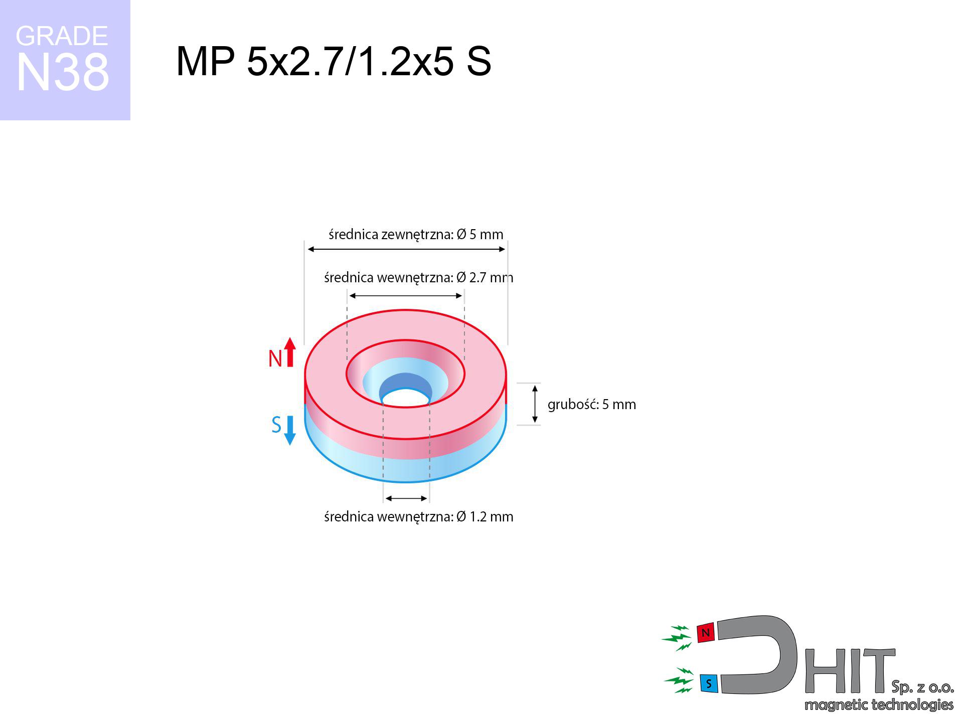
MP 5x2.7/1.2x5 S / N38 - ring magnet
ring magnet
Catalog no 030202
GTIN/EAN: 5906301812197
Diameter
5 mm [±0,1 mm]
internal diameter Ø
2.7/1.2 mm [±0,1 mm]
Height
5 mm [±0,1 mm]
Weight
0.69 g
Magnetization Direction
↑ axial
Load capacity
0.75 kg / 7.31 N
Magnetic Induction
553.14 mT / 5531 Gs
Coating
[NiCuNi] Nickel
0.836 ZŁ with VAT / pcs + price for transport
0.680 ZŁ net + 23% VAT / pcs
bulk discounts:
Need more?
Give us a call
+48 22 499 98 98
alternatively get in touch through
our online form
our website.
Weight along with form of neodymium magnets can be calculated using our
modular calculator.
Same-day shipping for orders placed before 14:00.
Detailed specification - MP 5x2.7/1.2x5 S / N38 - ring magnet
Specification / characteristics - MP 5x2.7/1.2x5 S / N38 - ring magnet
| properties | values |
|---|---|
| Cat. no. | 030202 |
| GTIN/EAN | 5906301812197 |
| Production/Distribution | Dhit sp. z o.o. |
| Country of origin | Poland / China / Germany |
| Customs code | 85059029 |
| Diameter | 5 mm [±0,1 mm] |
| internal diameter Ø | 2.7/1.2 mm [±0,1 mm] |
| Height | 5 mm [±0,1 mm] |
| Weight | 0.69 g |
| Magnetization Direction | ↑ axial |
| Load capacity ~ ? | 0.75 kg / 7.31 N |
| Magnetic Induction ~ ? | 553.14 mT / 5531 Gs |
| Coating | [NiCuNi] Nickel |
| Manufacturing Tolerance | ±0.1 mm |
Magnetic properties of material N38
| properties | values | units |
|---|---|---|
| remenance Br [min. - max.] ? | 12.2-12.6 | kGs |
| remenance Br [min. - max.] ? | 1220-1260 | mT |
| coercivity bHc ? | 10.8-11.5 | kOe |
| coercivity bHc ? | 860-915 | kA/m |
| actual internal force iHc | ≥ 12 | kOe |
| actual internal force iHc | ≥ 955 | kA/m |
| energy density [min. - max.] ? | 36-38 | BH max MGOe |
| energy density [min. - max.] ? | 287-303 | BH max KJ/m |
| max. temperature ? | ≤ 80 | °C |
Physical properties of sintered neodymium magnets Nd2Fe14B at 20°C
| properties | values | units |
|---|---|---|
| Vickers hardness | ≥550 | Hv |
| Density | ≥7.4 | g/cm3 |
| Curie Temperature TC | 312 - 380 | °C |
| Curie Temperature TF | 593 - 716 | °F |
| Specific resistance | 150 | μΩ⋅cm |
| Bending strength | 250 | MPa |
| Compressive strength | 1000~1100 | MPa |
| Thermal expansion parallel (∥) to orientation (M) | (3-4) x 10-6 | °C-1 |
| Thermal expansion perpendicular (⊥) to orientation (M) | -(1-3) x 10-6 | °C-1 |
| Young's modulus | 1.7 x 10⁴ | kg/mm² |
Technical simulation of the magnet - data
The following values constitute the outcome of a mathematical analysis. Values were calculated on models for the material Nd2Fe14B. Real-world conditions might slightly deviate from the simulation results. Treat these data as a reference point during assembly planning.
Table 1: Static pull force (pull vs distance) - interaction chart
MP 5x2.7/1.2x5 S / N38
| Distance (mm) | Induction (Gauss) / mT | Pull Force (kg/lbs/g/N) | Risk Status |
|---|---|---|---|
| 0 mm |
5322 Gs
532.2 mT
|
0.75 kg / 1.65 lbs
750.0 g / 7.4 N
|
low risk |
| 1 mm |
3295 Gs
329.5 mT
|
0.29 kg / 0.63 lbs
287.5 g / 2.8 N
|
low risk |
| 2 mm |
1883 Gs
188.3 mT
|
0.09 kg / 0.21 lbs
93.9 g / 0.9 N
|
low risk |
| 3 mm |
1098 Gs
109.8 mT
|
0.03 kg / 0.07 lbs
31.9 g / 0.3 N
|
low risk |
| 5 mm |
440 Gs
44.0 mT
|
0.01 kg / 0.01 lbs
5.1 g / 0.1 N
|
low risk |
| 10 mm |
92 Gs
9.2 mT
|
0.00 kg / 0.00 lbs
0.2 g / 0.0 N
|
low risk |
| 15 mm |
33 Gs
3.3 mT
|
0.00 kg / 0.00 lbs
0.0 g / 0.0 N
|
low risk |
| 20 mm |
15 Gs
1.5 mT
|
0.00 kg / 0.00 lbs
0.0 g / 0.0 N
|
low risk |
| 30 mm |
5 Gs
0.5 mT
|
0.00 kg / 0.00 lbs
0.0 g / 0.0 N
|
low risk |
| 50 mm |
1 Gs
0.1 mT
|
0.00 kg / 0.00 lbs
0.0 g / 0.0 N
|
low risk |
Table 2: Shear hold (vertical surface)
MP 5x2.7/1.2x5 S / N38
| Distance (mm) | Friction coefficient | Pull Force (kg/lbs/g/N) |
|---|---|---|
| 0 mm | Stal (~0.2) |
0.15 kg / 0.33 lbs
150.0 g / 1.5 N
|
| 1 mm | Stal (~0.2) |
0.06 kg / 0.13 lbs
58.0 g / 0.6 N
|
| 2 mm | Stal (~0.2) |
0.02 kg / 0.04 lbs
18.0 g / 0.2 N
|
| 3 mm | Stal (~0.2) |
0.01 kg / 0.01 lbs
6.0 g / 0.1 N
|
| 5 mm | Stal (~0.2) |
0.00 kg / 0.00 lbs
2.0 g / 0.0 N
|
| 10 mm | Stal (~0.2) |
0.00 kg / 0.00 lbs
0.0 g / 0.0 N
|
| 15 mm | Stal (~0.2) |
0.00 kg / 0.00 lbs
0.0 g / 0.0 N
|
| 20 mm | Stal (~0.2) |
0.00 kg / 0.00 lbs
0.0 g / 0.0 N
|
| 30 mm | Stal (~0.2) |
0.00 kg / 0.00 lbs
0.0 g / 0.0 N
|
| 50 mm | Stal (~0.2) |
0.00 kg / 0.00 lbs
0.0 g / 0.0 N
|
Table 3: Vertical assembly (shearing) - behavior on slippery surfaces
MP 5x2.7/1.2x5 S / N38
| Surface type | Friction coefficient / % Mocy | Max load (kg/lbs/g/N) |
|---|---|---|
| Raw steel |
µ = 0.3
30% Nominalnej Siły
|
0.22 kg / 0.50 lbs
225.0 g / 2.2 N
|
| Painted steel (standard) |
µ = 0.2
20% Nominalnej Siły
|
0.15 kg / 0.33 lbs
150.0 g / 1.5 N
|
| Oily/slippery steel |
µ = 0.1
10% Nominalnej Siły
|
0.08 kg / 0.17 lbs
75.0 g / 0.7 N
|
| Magnet with anti-slip rubber |
µ = 0.5
50% Nominalnej Siły
|
0.38 kg / 0.83 lbs
375.0 g / 3.7 N
|
Table 4: Steel thickness (saturation) - power losses
MP 5x2.7/1.2x5 S / N38
| Steel thickness (mm) | % power | Real pull force (kg/lbs/g/N) |
|---|---|---|
| 0.5 mm |
|
0.08 kg / 0.17 lbs
75.0 g / 0.7 N
|
| 1 mm |
|
0.19 kg / 0.41 lbs
187.5 g / 1.8 N
|
| 2 mm |
|
0.38 kg / 0.83 lbs
375.0 g / 3.7 N
|
| 3 mm |
|
0.56 kg / 1.24 lbs
562.5 g / 5.5 N
|
| 5 mm |
|
0.75 kg / 1.65 lbs
750.0 g / 7.4 N
|
| 10 mm |
|
0.75 kg / 1.65 lbs
750.0 g / 7.4 N
|
| 11 mm |
|
0.75 kg / 1.65 lbs
750.0 g / 7.4 N
|
| 12 mm |
|
0.75 kg / 1.65 lbs
750.0 g / 7.4 N
|
Table 5: Thermal resistance (stability) - thermal limit
MP 5x2.7/1.2x5 S / N38
| Ambient temp. (°C) | Power loss | Remaining pull (kg/lbs/g/N) | Status |
|---|---|---|---|
| 20 °C | 0.0% |
0.75 kg / 1.65 lbs
750.0 g / 7.4 N
|
OK |
| 40 °C | -2.2% |
0.73 kg / 1.62 lbs
733.5 g / 7.2 N
|
OK |
| 60 °C | -4.4% |
0.72 kg / 1.58 lbs
717.0 g / 7.0 N
|
OK |
| 80 °C | -6.6% |
0.70 kg / 1.54 lbs
700.5 g / 6.9 N
|
|
| 100 °C | -28.8% |
0.53 kg / 1.18 lbs
534.0 g / 5.2 N
|
Table 6: Two magnets (repulsion) - field range
MP 5x2.7/1.2x5 S / N38
| Gap (mm) | Attraction (kg/lbs) (N-S) | Shear Force (kg/lbs/g/N) | Repulsion (kg/lbs) (N-N) |
|---|---|---|---|
| 0 mm |
2.75 kg / 6.06 lbs
5 924 Gs
|
0.41 kg / 0.91 lbs
412 g / 4.0 N
|
N/A |
| 1 mm |
1.77 kg / 3.90 lbs
8 541 Gs
|
0.27 kg / 0.58 lbs
265 g / 2.6 N
|
1.59 kg / 3.51 lbs
~0 Gs
|
| 2 mm |
1.05 kg / 2.32 lbs
6 590 Gs
|
0.16 kg / 0.35 lbs
158 g / 1.5 N
|
0.95 kg / 2.09 lbs
~0 Gs
|
| 3 mm |
0.60 kg / 1.33 lbs
4 992 Gs
|
0.09 kg / 0.20 lbs
91 g / 0.9 N
|
0.54 kg / 1.20 lbs
~0 Gs
|
| 5 mm |
0.20 kg / 0.44 lbs
2 860 Gs
|
0.03 kg / 0.07 lbs
30 g / 0.3 N
|
0.18 kg / 0.39 lbs
~0 Gs
|
| 10 mm |
0.02 kg / 0.04 lbs
880 Gs
|
0.00 kg / 0.01 lbs
3 g / 0.0 N
|
0.02 kg / 0.04 lbs
~0 Gs
|
| 20 mm |
0.00 kg / 0.00 lbs
184 Gs
|
0.00 kg / 0.00 lbs
0 g / 0.0 N
|
0.00 kg / 0.00 lbs
~0 Gs
|
| 50 mm |
0.00 kg / 0.00 lbs
16 Gs
|
0.00 kg / 0.00 lbs
0 g / 0.0 N
|
0.00 kg / 0.00 lbs
~0 Gs
|
| 60 mm |
0.00 kg / 0.00 lbs
10 Gs
|
0.00 kg / 0.00 lbs
0 g / 0.0 N
|
0.00 kg / 0.00 lbs
~0 Gs
|
| 70 mm |
0.00 kg / 0.00 lbs
6 Gs
|
0.00 kg / 0.00 lbs
0 g / 0.0 N
|
0.00 kg / 0.00 lbs
~0 Gs
|
| 80 mm |
0.00 kg / 0.00 lbs
4 Gs
|
0.00 kg / 0.00 lbs
0 g / 0.0 N
|
0.00 kg / 0.00 lbs
~0 Gs
|
| 90 mm |
0.00 kg / 0.00 lbs
3 Gs
|
0.00 kg / 0.00 lbs
0 g / 0.0 N
|
0.00 kg / 0.00 lbs
~0 Gs
|
| 100 mm |
0.00 kg / 0.00 lbs
2 Gs
|
0.00 kg / 0.00 lbs
0 g / 0.0 N
|
0.00 kg / 0.00 lbs
~0 Gs
|
Table 7: Hazards (electronics) - precautionary measures
MP 5x2.7/1.2x5 S / N38
| Object / Device | Limit (Gauss) / mT | Safe distance |
|---|---|---|
| Pacemaker | 5 Gs (0.5 mT) | 3.0 cm |
| Hearing aid | 10 Gs (1.0 mT) | 2.5 cm |
| Mechanical watch | 20 Gs (2.0 mT) | 2.0 cm |
| Mobile device | 40 Gs (4.0 mT) | 1.5 cm |
| Remote | 50 Gs (5.0 mT) | 1.5 cm |
| Payment card | 400 Gs (40.0 mT) | 1.0 cm |
| HDD hard drive | 600 Gs (60.0 mT) | 0.5 cm |
Table 8: Dynamics (cracking risk) - warning
MP 5x2.7/1.2x5 S / N38
| Start from (mm) | Speed (km/h) | Energy (J) | Predicted outcome |
|---|---|---|---|
| 10 mm |
33.26 km/h
(9.24 m/s)
|
0.03 J | |
| 30 mm |
57.59 km/h
(16.00 m/s)
|
0.09 J | |
| 50 mm |
74.35 km/h
(20.65 m/s)
|
0.15 J | |
| 100 mm |
105.14 km/h
(29.21 m/s)
|
0.29 J |
Table 9: Anti-corrosion coating durability
MP 5x2.7/1.2x5 S / N38
| Technical parameter | Value / Description |
|---|---|
| Coating type | [NiCuNi] Nickel |
| Layer structure | Nickel - Copper - Nickel |
| Layer thickness | 10-20 µm |
| Salt spray test (SST) ? | 24 h |
| Recommended environment | Indoors only (dry) |
Table 10: Electrical data (Flux)
MP 5x2.7/1.2x5 S / N38
| Parameter | Value | SI Unit / Description |
|---|---|---|
| Magnetic Flux | 862 Mx | 8.6 µWb |
| Pc Coefficient | 0.83 | High (Stable) |
Table 11: Hydrostatics and buoyancy
MP 5x2.7/1.2x5 S / N38
| Environment | Effective steel pull | Effect |
|---|---|---|
| Air (land) | 0.75 kg | Standard |
| Water (riverbed) |
0.86 kg
(+0.11 kg buoyancy gain)
|
+14.5% |
1. Sliding resistance
*Caution: On a vertical wall, the magnet retains just approx. 20-30% of its nominal pull.
2. Efficiency vs thickness
*Thin metal sheet (e.g. computer case) severely weakens the holding force.
3. Temperature resistance
*For N38 material, the max working temp is 80°C.
4. Demagnetization curve and operating point (B-H)
chart generated for the permeance coefficient Pc (Permeance Coefficient) = 0.83
The chart above illustrates the magnetic characteristics of the material within the second quadrant of the hysteresis loop. The solid red line represents the demagnetization curve (material potential), while the dashed blue line is the load line based on the magnet's geometry. The Pc (Permeance Coefficient), also known as the load line slope, is a dimensionless value that describes the relationship between the magnet's shape and its magnetic stability. The intersection of these two lines (the black dot) is the operating point — it determines the actual magnetic flux density generated by the magnet in this specific configuration. A higher Pc value means the magnet is more 'slender' (tall relative to its area), resulting in a higher operating point and better resistance to irreversible demagnetization caused by external fields or temperature. A value of 0.42 is relatively low (typical for flat magnets), meaning the operating point is closer to the 'knee' of the curve — caution is advised when operating at temperatures near the maximum limit to avoid strength loss.
Chemical composition
| iron (Fe) | 64% – 68% |
| neodymium (Nd) | 29% – 32% |
| boron (B) | 1.1% – 1.2% |
| dysprosium (Dy) | 0.5% – 2.0% |
| coating (Ni-Cu-Ni) | < 0.05% |
Ecology and recycling (GPSR)
| recyclability (EoL) | 100% |
| recycled raw materials | ~10% (pre-cons) |
| carbon footprint | low / zredukowany |
| waste code (EWC) | 16 02 16 |
View more deals


![AM szekla [M10] - magnetic accessories](https://cdn3.dhit.pl/graphics/products/am-szekla-m10-zeh.jpg "AM szekla [M10] - magnetic accessories")
![SM 32x325 [2xM8] / N52 - magnetic separator](https://cdn3.dhit.pl/graphics/products/sm-32x325-2xm8-xec.jpg "SM 32x325 [2xM8] / N52 - magnetic separator")
Pros and cons of neodymium magnets.
Pros
- They virtually do not lose strength, because even after 10 years the decline in efficiency is only ~1% (based on calculations),
- Magnets very well resist against loss of magnetization caused by external fields,
- A magnet with a smooth gold surface has better aesthetics,
- The surface of neodymium magnets generates a maximum magnetic field – this is a distinguishing feature,
- Through (appropriate) combination of ingredients, they can achieve high thermal strength, enabling operation at temperatures reaching 230°C and above...
- Considering the option of flexible forming and customization to specialized projects, NdFeB magnets can be manufactured in a broad palette of forms and dimensions, which increases their versatility,
- Universal use in advanced technology sectors – they serve a role in data components, electric motors, advanced medical instruments, as well as technologically advanced constructions.
- Compactness – despite small sizes they provide effective action, making them ideal for precision applications
Limitations
- At strong impacts they can crack, therefore we advise placing them in steel cases. A metal housing provides additional protection against damage and increases the magnet's durability.
- We warn that neodymium magnets can reduce their strength at high temperatures. To prevent this, we advise our specialized [AH] magnets, which work effectively even at 230°C.
- They oxidize in a humid environment. For use outdoors we recommend using waterproof magnets e.g. in rubber, plastic
- We suggest casing - magnetic mount, due to difficulties in realizing nuts inside the magnet and complex forms.
- Potential hazard resulting from small fragments of magnets pose a threat, when accidentally swallowed, which gains importance in the aspect of protecting the youngest. It is also worth noting that tiny parts of these products are able to be problematic in diagnostics medical in case of swallowing.
- Higher cost of purchase is a significant factor to consider compared to ceramic magnets, especially in budget applications
Lifting parameters
Magnetic strength at its maximum – what contributes to it?
- on a base made of structural steel, optimally conducting the magnetic flux
- whose thickness equals approx. 10 mm
- with an polished touching surface
- under conditions of ideal adhesion (surface-to-surface)
- under axial force direction (90-degree angle)
- at conditions approx. 20°C
Lifting capacity in practice – influencing factors
- Gap between magnet and steel – every millimeter of separation (caused e.g. by varnish or unevenness) diminishes the magnet efficiency, often by half at just 0.5 mm.
- Direction of force – highest force is available only during perpendicular pulling. The resistance to sliding of the magnet along the surface is typically many times lower (approx. 1/5 of the lifting capacity).
- Wall thickness – the thinner the sheet, the weaker the hold. Magnetic flux passes through the material instead of generating force.
- Chemical composition of the base – low-carbon steel attracts best. Alloy steels lower magnetic permeability and holding force.
- Smoothness – ideal contact is obtained only on smooth steel. Any scratches and bumps reduce the real contact area, reducing force.
- Thermal environment – temperature increase causes a temporary drop of induction. Check the maximum operating temperature for a given model.
Holding force was tested on a smooth steel plate of 20 mm thickness, when a perpendicular force was applied, whereas under parallel forces the lifting capacity is smaller. Additionally, even a slight gap between the magnet’s surface and the plate decreases the holding force.
Safe handling of neodymium magnets
Respect the power
Before use, check safety instructions. Uncontrolled attraction can break the magnet or injure your hand. Think ahead.
Warning for heart patients
Individuals with a heart stimulator have to maintain an absolute distance from magnets. The magnetic field can stop the functioning of the life-saving device.
This is not a toy
NdFeB magnets are not suitable for play. Swallowing a few magnets can lead to them connecting inside the digestive tract, which poses a severe health hazard and necessitates immediate surgery.
Do not drill into magnets
Powder generated during cutting of magnets is self-igniting. Avoid drilling into magnets unless you are an expert.
Do not overheat magnets
Avoid heat. Neodymium magnets are susceptible to temperature. If you need resistance above 80°C, inquire about special high-temperature series (H, SH, UH).
GPS and phone interference
GPS units and mobile phones are extremely sensitive to magnetism. Direct contact with a strong magnet can decalibrate the internal compass in your phone.
Skin irritation risks
Allergy Notice: The Ni-Cu-Ni coating contains nickel. If skin irritation happens, cease working with magnets and use protective gear.
Bodily injuries
Protect your hands. Two powerful magnets will snap together immediately with a force of several hundred kilograms, destroying everything in their path. Exercise extreme caution!
Material brittleness
NdFeB magnets are ceramic materials, meaning they are very brittle. Impact of two magnets will cause them cracking into shards.
Magnetic media
Intense magnetic fields can destroy records on credit cards, HDDs, and storage devices. Stay away of min. 10 cm.
Tabela kosztu i czasu dostawy
Płatność przed wysyłką:

GLS kurier
Przesyłka będzie u Ciebie za 2-3 dni
14.99 ZŁ

InPost Paczkomaty 24/7
Przesyłka będzie u Ciebie za 1-2 dni
12.30 ZŁ
Płatność przy odbiorze (pobranie):
GLS kurier
Przesyłka będzie u Ciebie za 1-2 dni
23.00 ZŁ
Rate the product
Your rating