
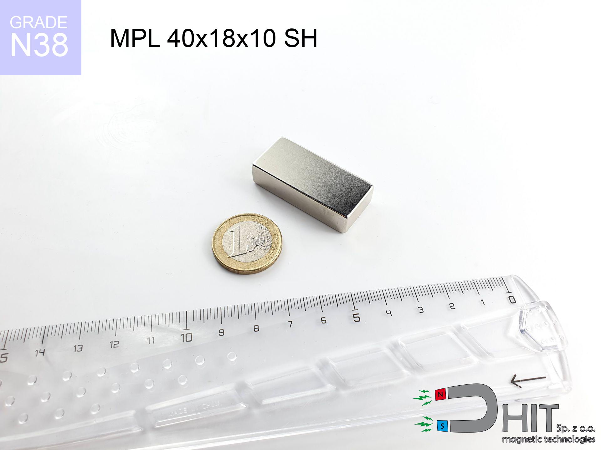
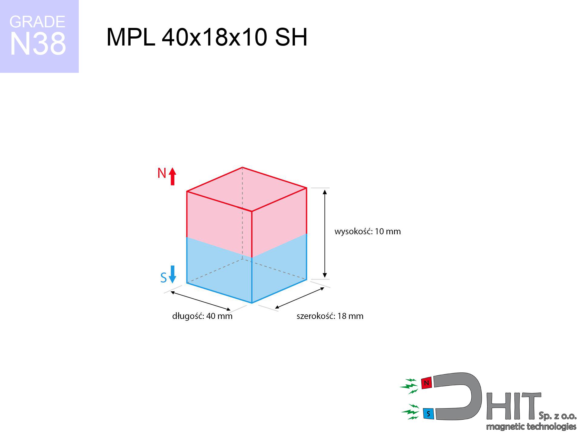
MPL 40x18x10 SH / N38 - lamellar magnet
lamellar magnet
Catalog no 020157
GTIN/EAN: 5906301811633
length
40 mm [±0,1 mm]
Width
18 mm [±0,1 mm]
Height
10 mm [±0,1 mm]
Weight
54 g
Magnetization Direction
↑ axial
Load capacity
23.81 kg / 233.58 N
Magnetic Induction
366.66 mT / 3667 Gs
Coating
[NiCuNi] Nickel
36.29 ZŁ with VAT / pcs + price for transport
29.50 ZŁ net + 23% VAT / pcs
bulk discounts:
Need more?
Contact us by phone
+48 22 499 98 98
otherwise get in touch using
contact form
the contact section.
Strength and appearance of magnetic components can be analyzed on our
magnetic calculator.
Same-day processing for orders placed before 14:00.
Technical specification of the product - MPL 40x18x10 SH / N38 - lamellar magnet
Specification / characteristics - MPL 40x18x10 SH / N38 - lamellar magnet
| properties | values |
|---|---|
| Cat. no. | 020157 |
| GTIN/EAN | 5906301811633 |
| Production/Distribution | Dhit sp. z o.o. |
| Country of origin | Poland / China / Germany |
| Customs code | 85059029 |
| length | 40 mm [±0,1 mm] |
| Width | 18 mm [±0,1 mm] |
| Height | 10 mm [±0,1 mm] |
| Weight | 54 g |
| Magnetization Direction | ↑ axial |
| Load capacity ~ ? | 23.81 kg / 233.58 N |
| Magnetic Induction ~ ? | 366.66 mT / 3667 Gs |
| Coating | [NiCuNi] Nickel |
| Manufacturing Tolerance | ±0.1 mm |
Magnetic properties of material N38
| properties | values | units |
|---|---|---|
| remenance Br [min. - max.] ? | 12.2-12.6 | kGs |
| remenance Br [min. - max.] ? | 1220-1260 | mT |
| coercivity bHc ? | 10.8-11.5 | kOe |
| coercivity bHc ? | 860-915 | kA/m |
| actual internal force iHc | ≥ 12 | kOe |
| actual internal force iHc | ≥ 955 | kA/m |
| energy density [min. - max.] ? | 36-38 | BH max MGOe |
| energy density [min. - max.] ? | 287-303 | BH max KJ/m |
| max. temperature ? | ≤ 80 | °C |
Physical properties of sintered neodymium magnets Nd2Fe14B at 20°C
| properties | values | units |
|---|---|---|
| Vickers hardness | ≥550 | Hv |
| Density | ≥7.4 | g/cm3 |
| Curie Temperature TC | 312 - 380 | °C |
| Curie Temperature TF | 593 - 716 | °F |
| Specific resistance | 150 | μΩ⋅cm |
| Bending strength | 250 | MPa |
| Compressive strength | 1000~1100 | MPa |
| Thermal expansion parallel (∥) to orientation (M) | (3-4) x 10-6 | °C-1 |
| Thermal expansion perpendicular (⊥) to orientation (M) | -(1-3) x 10-6 | °C-1 |
| Young's modulus | 1.7 x 10⁴ | kg/mm² |
Engineering simulation of the assembly - technical parameters
These information represent the direct effect of a mathematical calculation. Results were calculated on models for the class Nd2Fe14B. Real-world performance may deviate from the simulation results. Treat these calculations as a preliminary roadmap when designing systems.
Table 1: Static force (pull vs gap) - characteristics
MPL 40x18x10 SH / N38
| Distance (mm) | Induction (Gauss) / mT | Pull Force (kg/lbs/g/N) | Risk Status |
|---|---|---|---|
| 0 mm |
3666 Gs
366.6 mT
|
23.81 kg / 52.49 pounds
23810.0 g / 233.6 N
|
critical level |
| 1 mm |
3399 Gs
339.9 mT
|
20.48 kg / 45.14 pounds
20476.1 g / 200.9 N
|
critical level |
| 2 mm |
3120 Gs
312.0 mT
|
17.25 kg / 38.02 pounds
17245.9 g / 169.2 N
|
critical level |
| 3 mm |
2841 Gs
284.1 mT
|
14.30 kg / 31.54 pounds
14304.1 g / 140.3 N
|
critical level |
| 5 mm |
2321 Gs
232.1 mT
|
9.55 kg / 21.05 pounds
9547.8 g / 93.7 N
|
medium risk |
| 10 mm |
1370 Gs
137.0 mT
|
3.32 kg / 7.33 pounds
3324.4 g / 32.6 N
|
medium risk |
| 15 mm |
833 Gs
83.3 mT
|
1.23 kg / 2.71 pounds
1229.0 g / 12.1 N
|
low risk |
| 20 mm |
530 Gs
53.0 mT
|
0.50 kg / 1.10 pounds
498.1 g / 4.9 N
|
low risk |
| 30 mm |
244 Gs
24.4 mT
|
0.11 kg / 0.23 pounds
105.3 g / 1.0 N
|
low risk |
| 50 mm |
75 Gs
7.5 mT
|
0.01 kg / 0.02 pounds
9.9 g / 0.1 N
|
low risk |
Table 2: Slippage capacity (vertical surface)
MPL 40x18x10 SH / N38
| Distance (mm) | Friction coefficient | Pull Force (kg/lbs/g/N) |
|---|---|---|
| 0 mm | Stal (~0.2) |
4.76 kg / 10.50 pounds
4762.0 g / 46.7 N
|
| 1 mm | Stal (~0.2) |
4.10 kg / 9.03 pounds
4096.0 g / 40.2 N
|
| 2 mm | Stal (~0.2) |
3.45 kg / 7.61 pounds
3450.0 g / 33.8 N
|
| 3 mm | Stal (~0.2) |
2.86 kg / 6.31 pounds
2860.0 g / 28.1 N
|
| 5 mm | Stal (~0.2) |
1.91 kg / 4.21 pounds
1910.0 g / 18.7 N
|
| 10 mm | Stal (~0.2) |
0.66 kg / 1.46 pounds
664.0 g / 6.5 N
|
| 15 mm | Stal (~0.2) |
0.25 kg / 0.54 pounds
246.0 g / 2.4 N
|
| 20 mm | Stal (~0.2) |
0.10 kg / 0.22 pounds
100.0 g / 1.0 N
|
| 30 mm | Stal (~0.2) |
0.02 kg / 0.05 pounds
22.0 g / 0.2 N
|
| 50 mm | Stal (~0.2) |
0.00 kg / 0.00 pounds
2.0 g / 0.0 N
|
Table 3: Wall mounting (shearing) - behavior on slippery surfaces
MPL 40x18x10 SH / N38
| Surface type | Friction coefficient / % Mocy | Max load (kg/lbs/g/N) |
|---|---|---|
| Raw steel |
µ = 0.3
30% Nominalnej Siły
|
7.14 kg / 15.75 pounds
7143.0 g / 70.1 N
|
| Painted steel (standard) |
µ = 0.2
20% Nominalnej Siły
|
4.76 kg / 10.50 pounds
4762.0 g / 46.7 N
|
| Oily/slippery steel |
µ = 0.1
10% Nominalnej Siły
|
2.38 kg / 5.25 pounds
2381.0 g / 23.4 N
|
| Magnet with anti-slip rubber |
µ = 0.5
50% Nominalnej Siły
|
11.91 kg / 26.25 pounds
11905.0 g / 116.8 N
|
Table 4: Material efficiency (saturation) - power losses
MPL 40x18x10 SH / N38
| Steel thickness (mm) | % power | Real pull force (kg/lbs/g/N) |
|---|---|---|
| 0.5 mm |
|
1.19 kg / 2.62 pounds
1190.5 g / 11.7 N
|
| 1 mm |
|
2.98 kg / 6.56 pounds
2976.3 g / 29.2 N
|
| 2 mm |
|
5.95 kg / 13.12 pounds
5952.5 g / 58.4 N
|
| 3 mm |
|
8.93 kg / 19.68 pounds
8928.7 g / 87.6 N
|
| 5 mm |
|
14.88 kg / 32.81 pounds
14881.3 g / 146.0 N
|
| 10 mm |
|
23.81 kg / 52.49 pounds
23810.0 g / 233.6 N
|
| 11 mm |
|
23.81 kg / 52.49 pounds
23810.0 g / 233.6 N
|
| 12 mm |
|
23.81 kg / 52.49 pounds
23810.0 g / 233.6 N
|
Table 5: Working in heat (stability) - resistance threshold
MPL 40x18x10 SH / N38
| Ambient temp. (°C) | Power loss | Remaining pull (kg/lbs/g/N) | Status |
|---|---|---|---|
| 20 °C | 0.0% |
23.81 kg / 52.49 pounds
23810.0 g / 233.6 N
|
OK |
| 40 °C | -2.2% |
23.29 kg / 51.34 pounds
23286.2 g / 228.4 N
|
OK |
| 60 °C | -4.4% |
22.76 kg / 50.18 pounds
22762.4 g / 223.3 N
|
|
| 80 °C | -6.6% |
22.24 kg / 49.03 pounds
22238.5 g / 218.2 N
|
|
| 100 °C | -28.8% |
16.95 kg / 37.37 pounds
16952.7 g / 166.3 N
|
Table 6: Two magnets (attraction) - field collision
MPL 40x18x10 SH / N38
| Gap (mm) | Attraction (kg/lbs) (N-S) | Shear Strength (kg/lbs/g/N) | Repulsion (kg/lbs) (N-N) |
|---|---|---|---|
| 0 mm |
59.64 kg / 131.49 pounds
5 034 Gs
|
8.95 kg / 19.72 pounds
8947 g / 87.8 N
|
N/A |
| 1 mm |
55.50 kg / 122.35 pounds
7 072 Gs
|
8.32 kg / 18.35 pounds
8325 g / 81.7 N
|
49.95 kg / 110.12 pounds
~0 Gs
|
| 2 mm |
51.29 kg / 113.08 pounds
6 799 Gs
|
7.69 kg / 16.96 pounds
7694 g / 75.5 N
|
46.16 kg / 101.77 pounds
~0 Gs
|
| 3 mm |
47.18 kg / 104.01 pounds
6 520 Gs
|
7.08 kg / 15.60 pounds
7076 g / 69.4 N
|
42.46 kg / 93.61 pounds
~0 Gs
|
| 5 mm |
39.41 kg / 86.88 pounds
5 959 Gs
|
5.91 kg / 13.03 pounds
5912 g / 58.0 N
|
35.47 kg / 78.20 pounds
~0 Gs
|
| 10 mm |
23.92 kg / 52.73 pounds
4 643 Gs
|
3.59 kg / 7.91 pounds
3588 g / 35.2 N
|
21.53 kg / 47.46 pounds
~0 Gs
|
| 20 mm |
8.33 kg / 18.36 pounds
2 739 Gs
|
1.25 kg / 2.75 pounds
1249 g / 12.3 N
|
7.49 kg / 16.52 pounds
~0 Gs
|
| 50 mm |
0.55 kg / 1.22 pounds
705 Gs
|
0.08 kg / 0.18 pounds
83 g / 0.8 N
|
0.50 kg / 1.09 pounds
~0 Gs
|
| 60 mm |
0.26 kg / 0.58 pounds
487 Gs
|
0.04 kg / 0.09 pounds
40 g / 0.4 N
|
0.24 kg / 0.52 pounds
~0 Gs
|
| 70 mm |
0.13 kg / 0.30 pounds
348 Gs
|
0.02 kg / 0.04 pounds
20 g / 0.2 N
|
0.12 kg / 0.27 pounds
~0 Gs
|
| 80 mm |
0.07 kg / 0.16 pounds
256 Gs
|
0.01 kg / 0.02 pounds
11 g / 0.1 N
|
0.07 kg / 0.14 pounds
~0 Gs
|
| 90 mm |
0.04 kg / 0.09 pounds
194 Gs
|
0.01 kg / 0.01 pounds
6 g / 0.1 N
|
0.04 kg / 0.08 pounds
~0 Gs
|
| 100 mm |
0.02 kg / 0.05 pounds
149 Gs
|
0.00 kg / 0.01 pounds
4 g / 0.0 N
|
0.02 kg / 0.05 pounds
~0 Gs
|
Table 7: Safety (HSE) (electronics) - precautionary measures
MPL 40x18x10 SH / N38
| Object / Device | Limit (Gauss) / mT | Safe distance |
|---|---|---|
| Pacemaker | 5 Gs (0.5 mT) | 14.0 cm |
| Hearing aid | 10 Gs (1.0 mT) | 11.0 cm |
| Mechanical watch | 20 Gs (2.0 mT) | 8.5 cm |
| Mobile device | 40 Gs (4.0 mT) | 6.5 cm |
| Remote | 50 Gs (5.0 mT) | 6.0 cm |
| Payment card | 400 Gs (40.0 mT) | 2.5 cm |
| HDD hard drive | 600 Gs (60.0 mT) | 2.0 cm |
Table 8: Impact energy (kinetic energy) - collision effects
MPL 40x18x10 SH / N38
| Start from (mm) | Speed (km/h) | Energy (J) | Predicted outcome |
|---|---|---|---|
| 10 mm |
22.95 km/h
(6.38 m/s)
|
1.10 J | |
| 30 mm |
36.78 km/h
(10.22 m/s)
|
2.82 J | |
| 50 mm |
47.37 km/h
(13.16 m/s)
|
4.67 J | |
| 100 mm |
66.97 km/h
(18.60 m/s)
|
9.34 J |
Table 9: Coating parameters (durability)
MPL 40x18x10 SH / N38
| Technical parameter | Value / Description |
|---|---|
| Coating type | [NiCuNi] Nickel |
| Layer structure | Nickel - Copper - Nickel |
| Layer thickness | 10-20 µm |
| Salt spray test (SST) ? | 24 h |
| Recommended environment | Indoors only (dry) |
Table 10: Construction data (Flux)
MPL 40x18x10 SH / N38
| Parameter | Value | SI Unit / Description |
|---|---|---|
| Magnetic Flux | 26 060 Mx | 260.6 µWb |
| Pc Coefficient | 0.43 | Low (Flat) |
Table 11: Physics of underwater searching
MPL 40x18x10 SH / N38
| Environment | Effective steel pull | Effect |
|---|---|---|
| Air (land) | 23.81 kg | Standard |
| Water (riverbed) |
27.26 kg
(+3.45 kg buoyancy gain)
|
+14.5% |
1. Vertical hold
*Caution: On a vertical wall, the magnet holds merely approx. 20-30% of its nominal pull.
2. Efficiency vs thickness
*Thin metal sheet (e.g. 0.5mm PC case) drastically limits the holding force.
3. Temperature resistance
*For N38 grade, the safety limit is 80°C.
4. Demagnetization curve and operating point (B-H)
chart generated for the permeance coefficient Pc (Permeance Coefficient) = 0.43
This simulation demonstrates the magnetic stability of the selected magnet under specific geometric conditions. The solid red line represents the demagnetization curve (material potential), while the dashed blue line is the load line based on the magnet's geometry. The Pc (Permeance Coefficient), also known as the load line slope, is a dimensionless value that describes the relationship between the magnet's shape and its magnetic stability. The intersection of these two lines (the black dot) is the operating point — it determines the actual magnetic flux density generated by the magnet in this specific configuration. A higher Pc value means the magnet is more 'slender' (tall relative to its area), resulting in a higher operating point and better resistance to irreversible demagnetization caused by external fields or temperature. A value of 0.42 is relatively low (typical for flat magnets), meaning the operating point is closer to the 'knee' of the curve — caution is advised when operating at temperatures near the maximum limit to avoid strength loss.
Elemental analysis
| iron (Fe) | 64% – 68% |
| neodymium (Nd) | 29% – 32% |
| boron (B) | 1.1% – 1.2% |
| dysprosium (Dy) | 0.5% – 2.0% |
| coating (Ni-Cu-Ni) | < 0.05% |
Environmental data
| recyclability (EoL) | 100% |
| recycled raw materials | ~10% (pre-cons) |
| carbon footprint | low / zredukowany |
| waste code (EWC) | 16 02 16 |
Other offers
![AM szekla [M10] - magnetic accessories](https://cdn3.dhit.pl/graphics/products/am-szekla-m10-zeh.jpg "AM szekla [M10] - magnetic accessories")
![SM 32x325 [2xM8] / N52 - magnetic separator](https://cdn3.dhit.pl/graphics/products/sm-32x325-2xm8-xec.jpg "SM 32x325 [2xM8] / N52 - magnetic separator")
![UMH 16x5x32 [M4] / N38 - magnetic holder with hook](https://cdn3.dhit.pl/graphics/products/umh-16x5x32-m4-lak.jpg "UMH 16x5x32 [M4] / N38 - magnetic holder with hook")

Pros and cons of neodymium magnets.
Benefits
- Their strength is maintained, and after around 10 years it drops only by ~1% (theoretically),
- They have excellent resistance to magnetism drop as a result of opposing magnetic fields,
- The use of an elegant finish of noble metals (nickel, gold, silver) causes the element to look better,
- Magnets have maximum magnetic induction on the surface,
- Neodymium magnets are characterized by extremely high magnetic induction on the magnet surface and can work (depending on the form) even at a temperature of 230°C or more...
- In view of the ability of flexible shaping and customization to individualized needs, neodymium magnets can be modeled in a wide range of forms and dimensions, which makes them more universal,
- Fundamental importance in future technologies – they find application in mass storage devices, electromotive mechanisms, advanced medical instruments, as well as complex engineering applications.
- Relatively small size with high pulling force – neodymium magnets offer strong magnetic field in tiny dimensions, which makes them useful in small systems
Cons
- To avoid cracks upon strong impacts, we suggest using special steel housings. Such a solution protects the magnet and simultaneously increases its durability.
- When exposed to high temperature, neodymium magnets experience a drop in strength. Often, when the temperature exceeds 80°C, their power decreases (depending on the size, as well as shape of the magnet). For those who need magnets for extreme conditions, we offer [AH] versions withstanding up to 230°C
- Magnets exposed to a humid environment can rust. Therefore when using outdoors, we suggest using water-impermeable magnets made of rubber, plastic or other material resistant to moisture
- Due to limitations in producing nuts and complicated shapes in magnets, we propose using casing - magnetic holder.
- Possible danger to health – tiny shards of magnets are risky, in case of ingestion, which is particularly important in the context of child safety. It is also worth noting that tiny parts of these products can complicate diagnosis medical after entering the body.
- With large orders the cost of neodymium magnets can be a barrier,
Holding force characteristics
Best holding force of the magnet in ideal parameters – what affects it?
- with the application of a yoke made of low-carbon steel, guaranteeing maximum field concentration
- with a thickness minimum 10 mm
- with an polished contact surface
- with zero gap (no coatings)
- during pulling in a direction perpendicular to the mounting surface
- at ambient temperature room level
Key elements affecting lifting force
- Gap between surfaces – even a fraction of a millimeter of distance (caused e.g. by varnish or dirt) diminishes the pulling force, often by half at just 0.5 mm.
- Force direction – note that the magnet has greatest strength perpendicularly. Under shear forces, the holding force drops significantly, often to levels of 20-30% of the nominal value.
- Element thickness – for full efficiency, the steel must be adequately massive. Thin sheet limits the attraction force (the magnet "punches through" it).
- Steel grade – the best choice is high-permeability steel. Hardened steels may attract less.
- Surface finish – ideal contact is possible only on smooth steel. Any scratches and bumps create air cushions, reducing force.
- Thermal factor – hot environment reduces pulling force. Too high temperature can permanently damage the magnet.
Lifting capacity was determined by applying a polished steel plate of suitable thickness (min. 20 mm), under perpendicular pulling force, in contrast under attempts to slide the magnet the load capacity is reduced by as much as fivefold. In addition, even a slight gap between the magnet and the plate reduces the load capacity.
Safety rules for work with NdFeB magnets
Keep away from children
Always keep magnets out of reach of children. Risk of swallowing is high, and the consequences of magnets connecting inside the body are fatal.
Dust is flammable
Mechanical processing of NdFeB material poses a fire hazard. Neodymium dust oxidizes rapidly with oxygen and is difficult to extinguish.
Finger safety
Large magnets can break fingers in a fraction of a second. Under no circumstances place your hand between two strong magnets.
Shattering risk
NdFeB magnets are sintered ceramics, which means they are very brittle. Clashing of two magnets will cause them shattering into small pieces.
Demagnetization risk
Do not overheat. Neodymium magnets are sensitive to temperature. If you need resistance above 80°C, look for HT versions (H, SH, UH).
Implant safety
People with a ICD have to maintain an safe separation from magnets. The magnetic field can stop the functioning of the implant.
Handling rules
Use magnets consciously. Their huge power can surprise even professionals. Plan your moves and respect their power.
Allergic reactions
Allergy Notice: The nickel-copper-nickel coating contains nickel. If redness occurs, cease working with magnets and wear gloves.
Precision electronics
GPS units and smartphones are extremely susceptible to magnetic fields. Close proximity with a powerful NdFeB magnet can ruin the internal compass in your phone.
Cards and drives
Do not bring magnets close to a purse, computer, or TV. The magnetic field can destroy these devices and wipe information from cards.
Tabela kosztu i czasu dostawy
Płatność przed wysyłką:

GLS kurier
Przesyłka będzie u Ciebie za 2-3 dni
14.99 ZŁ

InPost Paczkomaty 24/7
Przesyłka będzie u Ciebie za 1-2 dni
12.30 ZŁ
Płatność przy odbiorze (pobranie):
GLS kurier
Przesyłka będzie u Ciebie za 1-2 dni
23.00 ZŁ
Rate the product
Your rating