
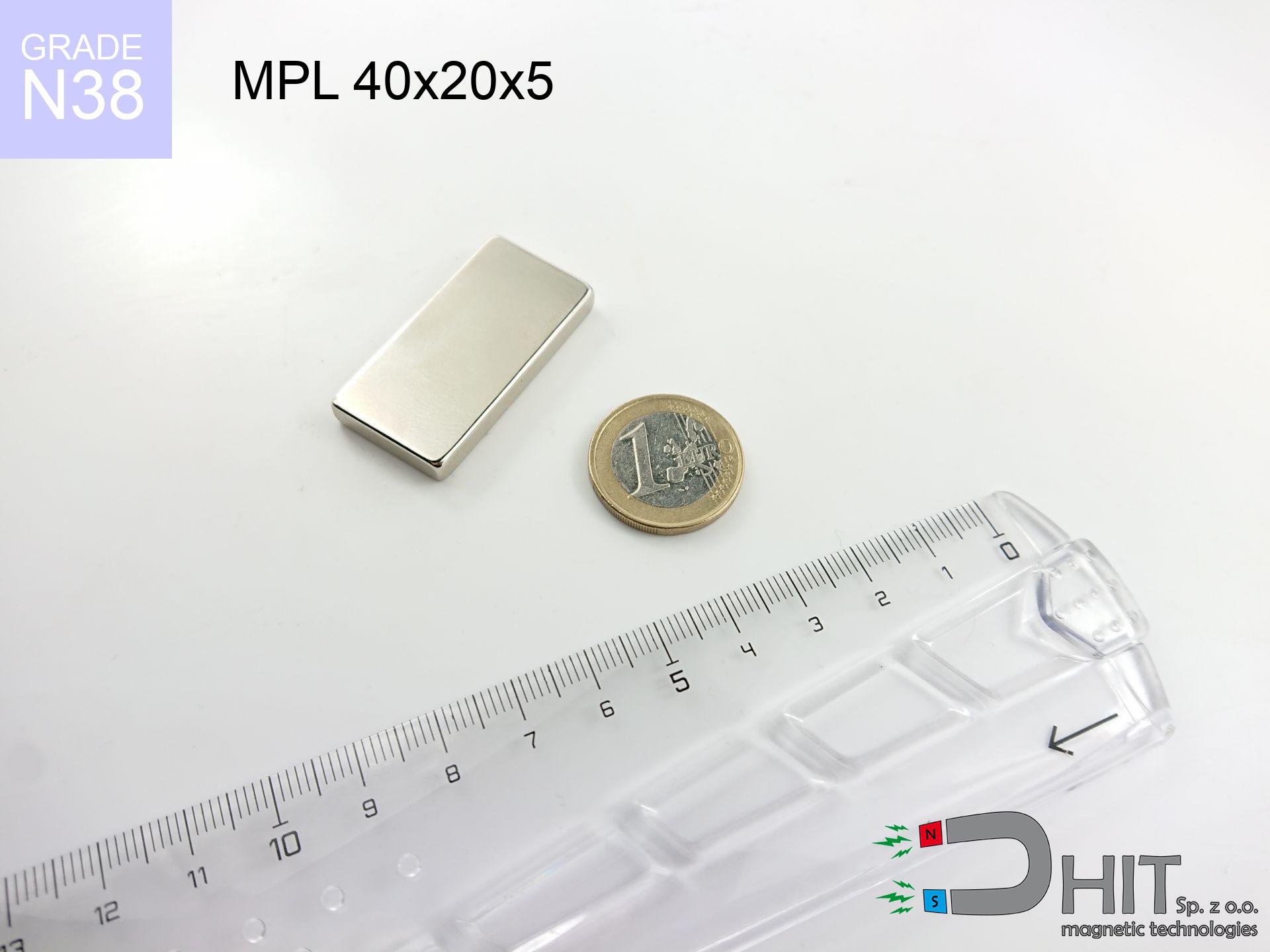
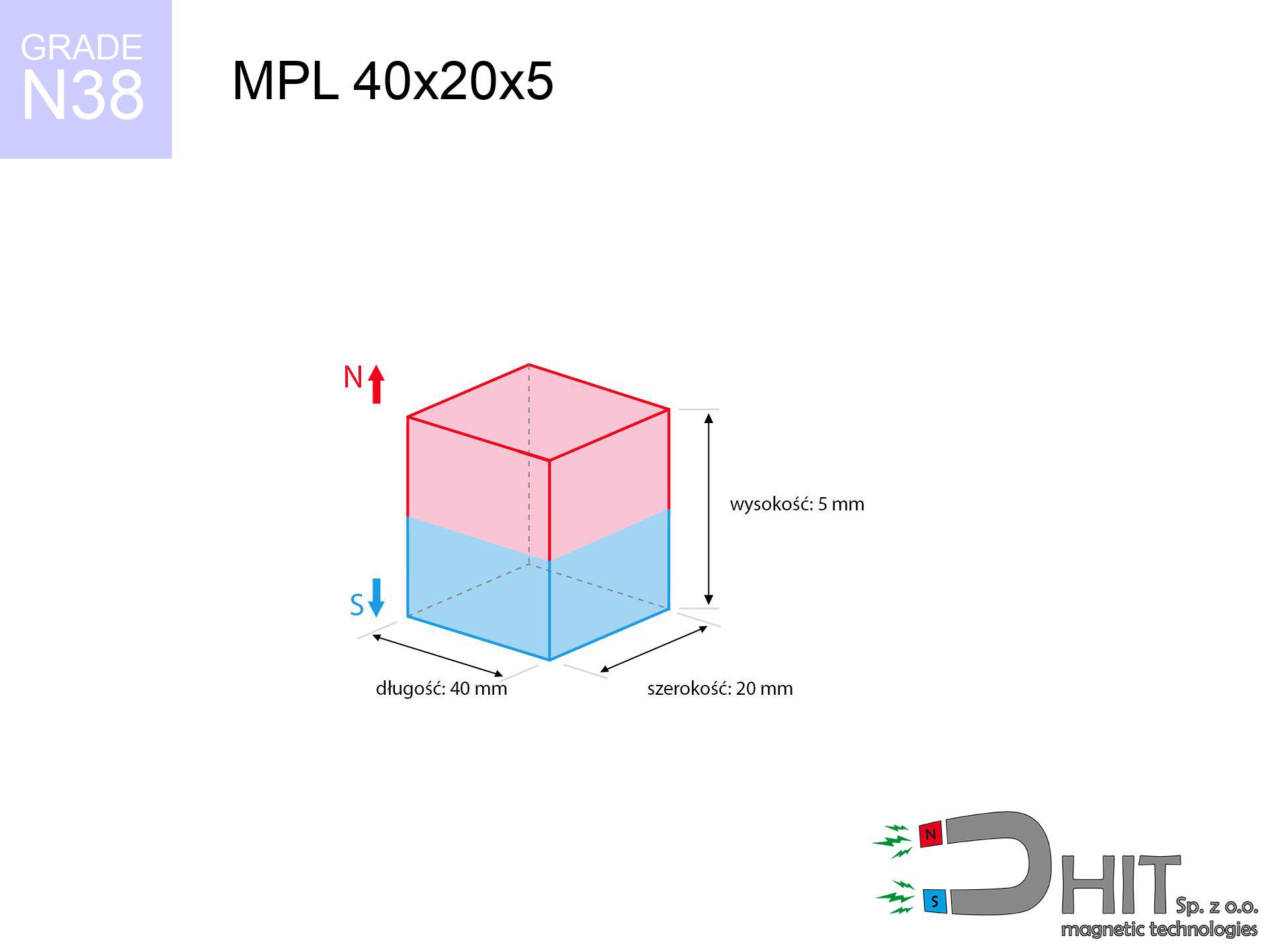
MPL 40x20x5 / N38 - lamellar magnet
lamellar magnet
Catalog no 020160
GTIN/EAN: 5906301811664
length
40 mm [±0,1 mm]
Width
20 mm [±0,1 mm]
Height
5 mm [±0,1 mm]
Weight
30 g
Magnetization Direction
↑ axial
Load capacity
10.67 kg / 104.63 N
Magnetic Induction
205.27 mT / 2053 Gs
Coating
[NiCuNi] Nickel
12.24 ZŁ with VAT / pcs + price for transport
9.95 ZŁ net + 23% VAT / pcs
bulk discounts:
Need more?
Pick up the phone and ask
+48 22 499 98 98
if you prefer send us a note through
request form
the contact form page.
Lifting power along with structure of neodymium magnets can be estimated using our
online calculation tool.
Same-day shipping for orders placed before 14:00.
Technical details - MPL 40x20x5 / N38 - lamellar magnet
Specification / characteristics - MPL 40x20x5 / N38 - lamellar magnet
| properties | values |
|---|---|
| Cat. no. | 020160 |
| GTIN/EAN | 5906301811664 |
| Production/Distribution | Dhit sp. z o.o. |
| Country of origin | Poland / China / Germany |
| Customs code | 85059029 |
| length | 40 mm [±0,1 mm] |
| Width | 20 mm [±0,1 mm] |
| Height | 5 mm [±0,1 mm] |
| Weight | 30 g |
| Magnetization Direction | ↑ axial |
| Load capacity ~ ? | 10.67 kg / 104.63 N |
| Magnetic Induction ~ ? | 205.27 mT / 2053 Gs |
| Coating | [NiCuNi] Nickel |
| Manufacturing Tolerance | ±0.1 mm |
Magnetic properties of material N38
| properties | values | units |
|---|---|---|
| remenance Br [min. - max.] ? | 12.2-12.6 | kGs |
| remenance Br [min. - max.] ? | 1220-1260 | mT |
| coercivity bHc ? | 10.8-11.5 | kOe |
| coercivity bHc ? | 860-915 | kA/m |
| actual internal force iHc | ≥ 12 | kOe |
| actual internal force iHc | ≥ 955 | kA/m |
| energy density [min. - max.] ? | 36-38 | BH max MGOe |
| energy density [min. - max.] ? | 287-303 | BH max KJ/m |
| max. temperature ? | ≤ 80 | °C |
Physical properties of sintered neodymium magnets Nd2Fe14B at 20°C
| properties | values | units |
|---|---|---|
| Vickers hardness | ≥550 | Hv |
| Density | ≥7.4 | g/cm3 |
| Curie Temperature TC | 312 - 380 | °C |
| Curie Temperature TF | 593 - 716 | °F |
| Specific resistance | 150 | μΩ⋅cm |
| Bending strength | 250 | MPa |
| Compressive strength | 1000~1100 | MPa |
| Thermal expansion parallel (∥) to orientation (M) | (3-4) x 10-6 | °C-1 |
| Thermal expansion perpendicular (⊥) to orientation (M) | -(1-3) x 10-6 | °C-1 |
| Young's modulus | 1.7 x 10⁴ | kg/mm² |
Technical modeling of the magnet - technical parameters
Presented data constitute the direct effect of a engineering calculation. Results rely on models for the class Nd2Fe14B. Actual performance may differ. Treat these calculations as a supplementary guide for designers.
Table 1: Static pull force (force vs gap) - power drop
MPL 40x20x5 / N38
| Distance (mm) | Induction (Gauss) / mT | Pull Force (kg/lbs/g/N) | Risk Status |
|---|---|---|---|
| 0 mm |
2052 Gs
205.2 mT
|
10.67 kg / 23.52 pounds
10670.0 g / 104.7 N
|
crushing |
| 1 mm |
1956 Gs
195.6 mT
|
9.69 kg / 21.37 pounds
9693.2 g / 95.1 N
|
medium risk |
| 2 mm |
1839 Gs
183.9 mT
|
8.57 kg / 18.89 pounds
8570.5 g / 84.1 N
|
medium risk |
| 3 mm |
1711 Gs
171.1 mT
|
7.41 kg / 16.34 pounds
7413.1 g / 72.7 N
|
medium risk |
| 5 mm |
1444 Gs
144.4 mT
|
5.28 kg / 11.65 pounds
5282.9 g / 51.8 N
|
medium risk |
| 10 mm |
888 Gs
88.8 mT
|
2.00 kg / 4.40 pounds
1996.5 g / 19.6 N
|
low risk |
| 15 mm |
545 Gs
54.5 mT
|
0.75 kg / 1.66 pounds
752.0 g / 7.4 N
|
low risk |
| 20 mm |
346 Gs
34.6 mT
|
0.30 kg / 0.67 pounds
302.9 g / 3.0 N
|
low risk |
| 30 mm |
156 Gs
15.6 mT
|
0.06 kg / 0.14 pounds
61.9 g / 0.6 N
|
low risk |
| 50 mm |
46 Gs
4.6 mT
|
0.01 kg / 0.01 pounds
5.4 g / 0.1 N
|
low risk |
Table 2: Sliding capacity (vertical surface)
MPL 40x20x5 / N38
| Distance (mm) | Friction coefficient | Pull Force (kg/lbs/g/N) |
|---|---|---|
| 0 mm | Stal (~0.2) |
2.13 kg / 4.70 pounds
2134.0 g / 20.9 N
|
| 1 mm | Stal (~0.2) |
1.94 kg / 4.27 pounds
1938.0 g / 19.0 N
|
| 2 mm | Stal (~0.2) |
1.71 kg / 3.78 pounds
1714.0 g / 16.8 N
|
| 3 mm | Stal (~0.2) |
1.48 kg / 3.27 pounds
1482.0 g / 14.5 N
|
| 5 mm | Stal (~0.2) |
1.06 kg / 2.33 pounds
1056.0 g / 10.4 N
|
| 10 mm | Stal (~0.2) |
0.40 kg / 0.88 pounds
400.0 g / 3.9 N
|
| 15 mm | Stal (~0.2) |
0.15 kg / 0.33 pounds
150.0 g / 1.5 N
|
| 20 mm | Stal (~0.2) |
0.06 kg / 0.13 pounds
60.0 g / 0.6 N
|
| 30 mm | Stal (~0.2) |
0.01 kg / 0.03 pounds
12.0 g / 0.1 N
|
| 50 mm | Stal (~0.2) |
0.00 kg / 0.00 pounds
2.0 g / 0.0 N
|
Table 3: Wall mounting (shearing) - vertical pull
MPL 40x20x5 / N38
| Surface type | Friction coefficient / % Mocy | Max load (kg/lbs/g/N) |
|---|---|---|
| Raw steel |
µ = 0.3
30% Nominalnej Siły
|
3.20 kg / 7.06 pounds
3201.0 g / 31.4 N
|
| Painted steel (standard) |
µ = 0.2
20% Nominalnej Siły
|
2.13 kg / 4.70 pounds
2134.0 g / 20.9 N
|
| Oily/slippery steel |
µ = 0.1
10% Nominalnej Siły
|
1.07 kg / 2.35 pounds
1067.0 g / 10.5 N
|
| Magnet with anti-slip rubber |
µ = 0.5
50% Nominalnej Siły
|
5.34 kg / 11.76 pounds
5335.0 g / 52.3 N
|
Table 4: Steel thickness (saturation) - power losses
MPL 40x20x5 / N38
| Steel thickness (mm) | % power | Real pull force (kg/lbs/g/N) |
|---|---|---|
| 0.5 mm |
|
0.53 kg / 1.18 pounds
533.5 g / 5.2 N
|
| 1 mm |
|
1.33 kg / 2.94 pounds
1333.8 g / 13.1 N
|
| 2 mm |
|
2.67 kg / 5.88 pounds
2667.5 g / 26.2 N
|
| 3 mm |
|
4.00 kg / 8.82 pounds
4001.2 g / 39.3 N
|
| 5 mm |
|
6.67 kg / 14.70 pounds
6668.8 g / 65.4 N
|
| 10 mm |
|
10.67 kg / 23.52 pounds
10670.0 g / 104.7 N
|
| 11 mm |
|
10.67 kg / 23.52 pounds
10670.0 g / 104.7 N
|
| 12 mm |
|
10.67 kg / 23.52 pounds
10670.0 g / 104.7 N
|
Table 5: Thermal resistance (material behavior) - power drop
MPL 40x20x5 / N38
| Ambient temp. (°C) | Power loss | Remaining pull (kg/lbs/g/N) | Status |
|---|---|---|---|
| 20 °C | 0.0% |
10.67 kg / 23.52 pounds
10670.0 g / 104.7 N
|
OK |
| 40 °C | -2.2% |
10.44 kg / 23.01 pounds
10435.3 g / 102.4 N
|
OK |
| 60 °C | -4.4% |
10.20 kg / 22.49 pounds
10200.5 g / 100.1 N
|
|
| 80 °C | -6.6% |
9.97 kg / 21.97 pounds
9965.8 g / 97.8 N
|
|
| 100 °C | -28.8% |
7.60 kg / 16.75 pounds
7597.0 g / 74.5 N
|
Table 6: Magnet-Magnet interaction (attraction) - field collision
MPL 40x20x5 / N38
| Gap (mm) | Attraction (kg/lbs) (N-S) | Sliding Force (kg/lbs/g/N) | Repulsion (kg/lbs) (N-N) |
|---|---|---|---|
| 0 mm |
20.78 kg / 45.80 pounds
3 495 Gs
|
3.12 kg / 6.87 pounds
3116 g / 30.6 N
|
N/A |
| 1 mm |
19.88 kg / 43.83 pounds
4 015 Gs
|
2.98 kg / 6.57 pounds
2982 g / 29.3 N
|
17.89 kg / 39.44 pounds
~0 Gs
|
| 2 mm |
18.87 kg / 41.61 pounds
3 912 Gs
|
2.83 kg / 6.24 pounds
2831 g / 27.8 N
|
16.99 kg / 37.45 pounds
~0 Gs
|
| 3 mm |
17.80 kg / 39.24 pounds
3 800 Gs
|
2.67 kg / 5.89 pounds
2670 g / 26.2 N
|
16.02 kg / 35.32 pounds
~0 Gs
|
| 5 mm |
15.56 kg / 34.30 pounds
3 552 Gs
|
2.33 kg / 5.14 pounds
2334 g / 22.9 N
|
14.00 kg / 30.87 pounds
~0 Gs
|
| 10 mm |
10.29 kg / 22.68 pounds
2 888 Gs
|
1.54 kg / 3.40 pounds
1543 g / 15.1 N
|
9.26 kg / 20.41 pounds
~0 Gs
|
| 20 mm |
3.89 kg / 8.57 pounds
1 776 Gs
|
0.58 kg / 1.29 pounds
583 g / 5.7 N
|
3.50 kg / 7.71 pounds
~0 Gs
|
| 50 mm |
0.26 kg / 0.57 pounds
456 Gs
|
0.04 kg / 0.08 pounds
39 g / 0.4 N
|
0.23 kg / 0.51 pounds
~0 Gs
|
| 60 mm |
0.12 kg / 0.27 pounds
313 Gs
|
0.02 kg / 0.04 pounds
18 g / 0.2 N
|
0.11 kg / 0.24 pounds
~0 Gs
|
| 70 mm |
0.06 kg / 0.13 pounds
221 Gs
|
0.01 kg / 0.02 pounds
9 g / 0.1 N
|
0.05 kg / 0.12 pounds
~0 Gs
|
| 80 mm |
0.03 kg / 0.07 pounds
162 Gs
|
0.00 kg / 0.01 pounds
5 g / 0.0 N
|
0.03 kg / 0.06 pounds
~0 Gs
|
| 90 mm |
0.02 kg / 0.04 pounds
121 Gs
|
0.00 kg / 0.01 pounds
3 g / 0.0 N
|
0.02 kg / 0.04 pounds
~0 Gs
|
| 100 mm |
0.01 kg / 0.02 pounds
93 Gs
|
0.00 kg / 0.00 pounds
2 g / 0.0 N
|
0.01 kg / 0.02 pounds
~0 Gs
|
Table 7: Hazards (implants) - precautionary measures
MPL 40x20x5 / N38
| Object / Device | Limit (Gauss) / mT | Safe distance |
|---|---|---|
| Pacemaker | 5 Gs (0.5 mT) | 11.5 cm |
| Hearing aid | 10 Gs (1.0 mT) | 9.0 cm |
| Mechanical watch | 20 Gs (2.0 mT) | 7.0 cm |
| Phone / Smartphone | 40 Gs (4.0 mT) | 5.5 cm |
| Car key | 50 Gs (5.0 mT) | 5.0 cm |
| Payment card | 400 Gs (40.0 mT) | 2.0 cm |
| HDD hard drive | 600 Gs (60.0 mT) | 1.5 cm |
Table 8: Collisions (cracking risk) - warning
MPL 40x20x5 / N38
| Start from (mm) | Speed (km/h) | Energy (J) | Predicted outcome |
|---|---|---|---|
| 10 mm |
21.13 km/h
(5.87 m/s)
|
0.52 J | |
| 30 mm |
33.06 km/h
(9.18 m/s)
|
1.27 J | |
| 50 mm |
42.54 km/h
(11.82 m/s)
|
2.09 J | |
| 100 mm |
60.15 km/h
(16.71 m/s)
|
4.19 J |
Table 9: Anti-corrosion coating durability
MPL 40x20x5 / N38
| Technical parameter | Value / Description |
|---|---|
| Coating type | [NiCuNi] Nickel |
| Layer structure | Nickel - Copper - Nickel |
| Layer thickness | 10-20 µm |
| Salt spray test (SST) ? | 24 h |
| Recommended environment | Indoors only (dry) |
Table 10: Construction data (Flux)
MPL 40x20x5 / N38
| Parameter | Value | SI Unit / Description |
|---|---|---|
| Magnetic Flux | 18 042 Mx | 180.4 µWb |
| Pc Coefficient | 0.23 | Low (Flat) |
Table 11: Physics of underwater searching
MPL 40x20x5 / N38
| Environment | Effective steel pull | Effect |
|---|---|---|
| Air (land) | 10.67 kg | Standard |
| Water (riverbed) |
12.22 kg
(+1.55 kg buoyancy gain)
|
+14.5% |
1. Vertical hold
*Caution: On a vertical surface, the magnet retains only ~20% of its perpendicular strength.
2. Efficiency vs thickness
*Thin steel (e.g. 0.5mm PC case) severely reduces the holding force.
3. Temperature resistance
*For N38 grade, the max working temp is 80°C.
4. Demagnetization curve and operating point (B-H)
chart generated for the permeance coefficient Pc (Permeance Coefficient) = 0.23
The chart above illustrates the magnetic characteristics of the material within the second quadrant of the hysteresis loop. The solid red line represents the demagnetization curve (material potential), while the dashed blue line is the load line based on the magnet's geometry. The Pc (Permeance Coefficient), also known as the load line slope, is a dimensionless value that describes the relationship between the magnet's shape and its magnetic stability. The intersection of these two lines (the black dot) is the operating point — it determines the actual magnetic flux density generated by the magnet in this specific configuration. A higher Pc value means the magnet is more 'slender' (tall relative to its area), resulting in a higher operating point and better resistance to irreversible demagnetization caused by external fields or temperature. A value of 0.42 is relatively low (typical for flat magnets), meaning the operating point is closer to the 'knee' of the curve — caution is advised when operating at temperatures near the maximum limit to avoid strength loss.
Material specification
| iron (Fe) | 64% – 68% |
| neodymium (Nd) | 29% – 32% |
| boron (B) | 1.1% – 1.2% |
| dysprosium (Dy) | 0.5% – 2.0% |
| coating (Ni-Cu-Ni) | < 0.05% |
Ecology and recycling (GPSR)
| recyclability (EoL) | 100% |
| recycled raw materials | ~10% (pre-cons) |
| carbon footprint | low / zredukowany |
| waste code (EWC) | 16 02 16 |
Other deals
![UMGGW 43x6 [M4] GW / N38 - magnetic holder rubber internal thread](https://cdn3.dhit.pl/graphics/products/umg-43x6-m6-gw-hel.jpg "UMGGW 43x6 [M4] GW / N38 - magnetic holder rubber internal thread")
![SM 25x275 [2xM8] / N42 - magnetic separator](https://cdn3.dhit.pl/graphics/products/sm-25x275-2xm8-boc.jpg "SM 25x275 [2xM8] / N42 - magnetic separator")


Strengths and weaknesses of rare earth magnets.
Benefits
- They retain full power for around 10 years – the loss is just ~1% (in theory),
- Magnets very well defend themselves against demagnetization caused by ambient magnetic noise,
- The use of an refined coating of noble metals (nickel, gold, silver) causes the element to have aesthetics,
- The surface of neodymium magnets generates a strong magnetic field – this is a key feature,
- Made from properly selected components, these magnets show impressive resistance to high heat, enabling them to function (depending on their form) at temperatures up to 230°C and above...
- Possibility of exact creating as well as adapting to defined conditions,
- Versatile presence in future technologies – they serve a role in HDD drives, brushless drives, diagnostic systems, and modern systems.
- Compactness – despite small sizes they provide effective action, making them ideal for precision applications
Limitations
- Brittleness is one of their disadvantages. Upon strong impact they can fracture. We recommend keeping them in a steel housing, which not only protects them against impacts but also raises their durability
- Neodymium magnets lose their force under the influence of heating. As soon as 80°C is exceeded, many of them start losing their force. Therefore, we recommend our special magnets marked [AH], which maintain durability even at temperatures up to 230°C
- When exposed to humidity, magnets usually rust. To use them in conditions outside, it is recommended to use protective magnets, such as magnets in rubber or plastics, which prevent oxidation and corrosion.
- Limited ability of creating threads in the magnet and complex shapes - recommended is cover - magnet mounting.
- Health risk related to microscopic parts of magnets can be dangerous, in case of ingestion, which is particularly important in the aspect of protecting the youngest. Furthermore, small elements of these magnets are able to disrupt the diagnostic process medical when they are in the body.
- High unit price – neodymium magnets cost more than other types of magnets (e.g. ferrite), which hinders application in large quantities
Pull force analysis
Magnetic strength at its maximum – what contributes to it?
- on a block made of structural steel, effectively closing the magnetic field
- whose transverse dimension equals approx. 10 mm
- with a surface perfectly flat
- without the slightest insulating layer between the magnet and steel
- for force acting at a right angle (pull-off, not shear)
- at standard ambient temperature
Key elements affecting lifting force
- Space between surfaces – even a fraction of a millimeter of separation (caused e.g. by veneer or unevenness) diminishes the magnet efficiency, often by half at just 0.5 mm.
- Pull-off angle – note that the magnet has greatest strength perpendicularly. Under sliding down, the capacity drops significantly, often to levels of 20-30% of the nominal value.
- Metal thickness – the thinner the sheet, the weaker the hold. Part of the magnetic field passes through the material instead of generating force.
- Chemical composition of the base – low-carbon steel gives the best results. Higher carbon content lower magnetic properties and lifting capacity.
- Surface finish – full contact is obtained only on smooth steel. Rough texture create air cushions, weakening the magnet.
- Temperature influence – hot environment reduces magnetic field. Exceeding the limit temperature can permanently damage the magnet.
Holding force was tested on a smooth steel plate of 20 mm thickness, when the force acted perpendicularly, whereas under parallel forces the load capacity is reduced by as much as fivefold. In addition, even a slight gap between the magnet and the plate decreases the lifting capacity.
H&S for magnets
Choking Hazard
Adult use only. Tiny parts pose a choking risk, causing severe trauma. Store out of reach of children and animals.
Protective goggles
NdFeB magnets are ceramic materials, which means they are fragile like glass. Clashing of two magnets leads to them shattering into small pieces.
Keep away from electronics
Remember: neodymium magnets produce a field that disrupts precision electronics. Maintain a separation from your mobile, device, and navigation systems.
Do not drill into magnets
Dust generated during machining of magnets is self-igniting. Do not drill into magnets without proper cooling and knowledge.
Medical implants
Medical warning: Neodymium magnets can deactivate heart devices and defibrillators. Stay away if you have electronic implants.
Nickel allergy
A percentage of the population have a sensitization to Ni, which is the typical protective layer for NdFeB magnets. Extended handling may cause an allergic reaction. It is best to use protective gloves.
Electronic hazard
Intense magnetic fields can erase data on payment cards, HDDs, and other magnetic media. Keep a distance of min. 10 cm.
Crushing force
Mind your fingers. Two powerful magnets will join immediately with a force of massive weight, crushing everything in their path. Be careful!
Demagnetization risk
Keep cool. Neodymium magnets are susceptible to heat. If you need resistance above 80°C, ask us about HT versions (H, SH, UH).
Handling guide
Before starting, check safety instructions. Sudden snapping can destroy the magnet or hurt your hand. Think ahead.
Tabela kosztu i czasu dostawy
Płatność przed wysyłką:

GLS kurier
Przesyłka będzie u Ciebie za 2-3 dni
14.99 ZŁ

InPost Paczkomaty 24/7
Przesyłka będzie u Ciebie za 1-2 dni
12.30 ZŁ
Płatność przy odbiorze (pobranie):
GLS kurier
Przesyłka będzie u Ciebie za 1-2 dni
23.00 ZŁ
Rate the product
Your rating