
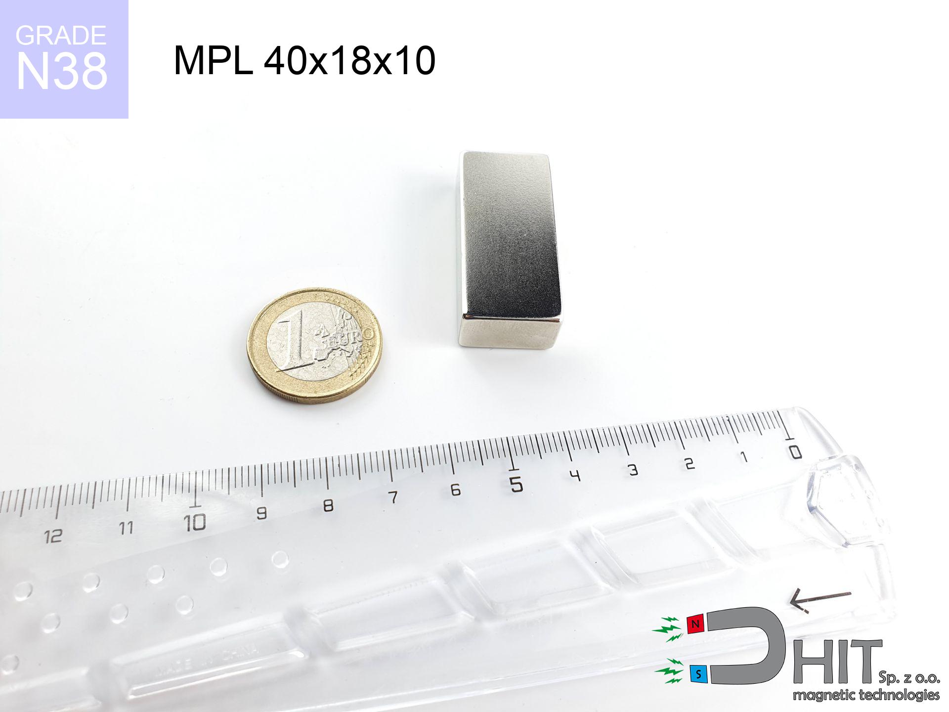
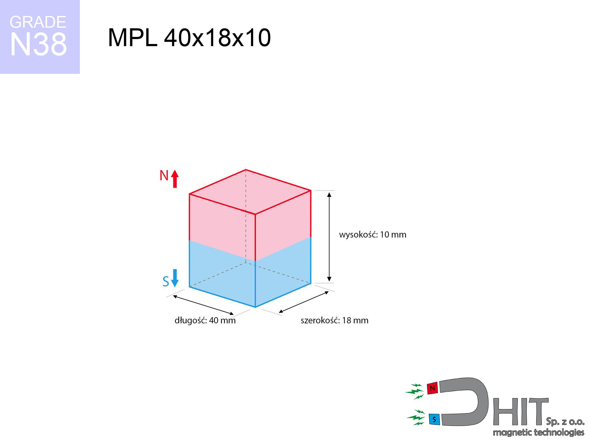
MPL 40x18x10 / N38 - lamellar magnet
lamellar magnet
Catalog no 020156
GTIN/EAN: 5906301811626
length
40 mm [±0,1 mm]
Width
18 mm [±0,1 mm]
Height
10 mm [±0,1 mm]
Weight
54 g
Magnetization Direction
↑ axial
Load capacity
23.81 kg / 233.58 N
Magnetic Induction
366.66 mT / 3667 Gs
Coating
[NiCuNi] Nickel
30.75 ZŁ with VAT / pcs + price for transport
25.00 ZŁ net + 23% VAT / pcs
bulk discounts:
Need more?
Call us now
+48 22 499 98 98
otherwise let us know via
request form
through our site.
Specifications and structure of neodymium magnets can be analyzed with our
online calculation tool.
Order by 14:00 and we’ll ship today!
Physical properties - MPL 40x18x10 / N38 - lamellar magnet
Specification / characteristics - MPL 40x18x10 / N38 - lamellar magnet
| properties | values |
|---|---|
| Cat. no. | 020156 |
| GTIN/EAN | 5906301811626 |
| Production/Distribution | Dhit sp. z o.o. |
| Country of origin | Poland / China / Germany |
| Customs code | 85059029 |
| length | 40 mm [±0,1 mm] |
| Width | 18 mm [±0,1 mm] |
| Height | 10 mm [±0,1 mm] |
| Weight | 54 g |
| Magnetization Direction | ↑ axial |
| Load capacity ~ ? | 23.81 kg / 233.58 N |
| Magnetic Induction ~ ? | 366.66 mT / 3667 Gs |
| Coating | [NiCuNi] Nickel |
| Manufacturing Tolerance | ±0.1 mm |
Magnetic properties of material N38
| properties | values | units |
|---|---|---|
| remenance Br [min. - max.] ? | 12.2-12.6 | kGs |
| remenance Br [min. - max.] ? | 1220-1260 | mT |
| coercivity bHc ? | 10.8-11.5 | kOe |
| coercivity bHc ? | 860-915 | kA/m |
| actual internal force iHc | ≥ 12 | kOe |
| actual internal force iHc | ≥ 955 | kA/m |
| energy density [min. - max.] ? | 36-38 | BH max MGOe |
| energy density [min. - max.] ? | 287-303 | BH max KJ/m |
| max. temperature ? | ≤ 80 | °C |
Physical properties of sintered neodymium magnets Nd2Fe14B at 20°C
| properties | values | units |
|---|---|---|
| Vickers hardness | ≥550 | Hv |
| Density | ≥7.4 | g/cm3 |
| Curie Temperature TC | 312 - 380 | °C |
| Curie Temperature TF | 593 - 716 | °F |
| Specific resistance | 150 | μΩ⋅cm |
| Bending strength | 250 | MPa |
| Compressive strength | 1000~1100 | MPa |
| Thermal expansion parallel (∥) to orientation (M) | (3-4) x 10-6 | °C-1 |
| Thermal expansion perpendicular (⊥) to orientation (M) | -(1-3) x 10-6 | °C-1 |
| Young's modulus | 1.7 x 10⁴ | kg/mm² |
Technical modeling of the product - data
These information constitute the outcome of a engineering simulation. Values rely on algorithms for the material Nd2Fe14B. Actual parameters might slightly differ. Use these data as a preliminary roadmap for designers.
Table 1: Static force (force vs gap) - power drop
MPL 40x18x10 / N38
| Distance (mm) | Induction (Gauss) / mT | Pull Force (kg/lbs/g/N) | Risk Status |
|---|---|---|---|
| 0 mm |
3666 Gs
366.6 mT
|
23.81 kg / 52.49 lbs
23810.0 g / 233.6 N
|
critical level |
| 1 mm |
3399 Gs
339.9 mT
|
20.48 kg / 45.14 lbs
20476.1 g / 200.9 N
|
critical level |
| 2 mm |
3120 Gs
312.0 mT
|
17.25 kg / 38.02 lbs
17245.9 g / 169.2 N
|
critical level |
| 3 mm |
2841 Gs
284.1 mT
|
14.30 kg / 31.54 lbs
14304.1 g / 140.3 N
|
critical level |
| 5 mm |
2321 Gs
232.1 mT
|
9.55 kg / 21.05 lbs
9547.8 g / 93.7 N
|
strong |
| 10 mm |
1370 Gs
137.0 mT
|
3.32 kg / 7.33 lbs
3324.4 g / 32.6 N
|
strong |
| 15 mm |
833 Gs
83.3 mT
|
1.23 kg / 2.71 lbs
1229.0 g / 12.1 N
|
weak grip |
| 20 mm |
530 Gs
53.0 mT
|
0.50 kg / 1.10 lbs
498.1 g / 4.9 N
|
weak grip |
| 30 mm |
244 Gs
24.4 mT
|
0.11 kg / 0.23 lbs
105.3 g / 1.0 N
|
weak grip |
| 50 mm |
75 Gs
7.5 mT
|
0.01 kg / 0.02 lbs
9.9 g / 0.1 N
|
weak grip |
Table 2: Vertical load (wall)
MPL 40x18x10 / N38
| Distance (mm) | Friction coefficient | Pull Force (kg/lbs/g/N) |
|---|---|---|
| 0 mm | Stal (~0.2) |
4.76 kg / 10.50 lbs
4762.0 g / 46.7 N
|
| 1 mm | Stal (~0.2) |
4.10 kg / 9.03 lbs
4096.0 g / 40.2 N
|
| 2 mm | Stal (~0.2) |
3.45 kg / 7.61 lbs
3450.0 g / 33.8 N
|
| 3 mm | Stal (~0.2) |
2.86 kg / 6.31 lbs
2860.0 g / 28.1 N
|
| 5 mm | Stal (~0.2) |
1.91 kg / 4.21 lbs
1910.0 g / 18.7 N
|
| 10 mm | Stal (~0.2) |
0.66 kg / 1.46 lbs
664.0 g / 6.5 N
|
| 15 mm | Stal (~0.2) |
0.25 kg / 0.54 lbs
246.0 g / 2.4 N
|
| 20 mm | Stal (~0.2) |
0.10 kg / 0.22 lbs
100.0 g / 1.0 N
|
| 30 mm | Stal (~0.2) |
0.02 kg / 0.05 lbs
22.0 g / 0.2 N
|
| 50 mm | Stal (~0.2) |
0.00 kg / 0.00 lbs
2.0 g / 0.0 N
|
Table 3: Wall mounting (sliding) - behavior on slippery surfaces
MPL 40x18x10 / N38
| Surface type | Friction coefficient / % Mocy | Max load (kg/lbs/g/N) |
|---|---|---|
| Raw steel |
µ = 0.3
30% Nominalnej Siły
|
7.14 kg / 15.75 lbs
7143.0 g / 70.1 N
|
| Painted steel (standard) |
µ = 0.2
20% Nominalnej Siły
|
4.76 kg / 10.50 lbs
4762.0 g / 46.7 N
|
| Oily/slippery steel |
µ = 0.1
10% Nominalnej Siły
|
2.38 kg / 5.25 lbs
2381.0 g / 23.4 N
|
| Magnet with anti-slip rubber |
µ = 0.5
50% Nominalnej Siły
|
11.91 kg / 26.25 lbs
11905.0 g / 116.8 N
|
Table 4: Material efficiency (substrate influence) - power losses
MPL 40x18x10 / N38
| Steel thickness (mm) | % power | Real pull force (kg/lbs/g/N) |
|---|---|---|
| 0.5 mm |
|
1.19 kg / 2.62 lbs
1190.5 g / 11.7 N
|
| 1 mm |
|
2.98 kg / 6.56 lbs
2976.3 g / 29.2 N
|
| 2 mm |
|
5.95 kg / 13.12 lbs
5952.5 g / 58.4 N
|
| 3 mm |
|
8.93 kg / 19.68 lbs
8928.7 g / 87.6 N
|
| 5 mm |
|
14.88 kg / 32.81 lbs
14881.3 g / 146.0 N
|
| 10 mm |
|
23.81 kg / 52.49 lbs
23810.0 g / 233.6 N
|
| 11 mm |
|
23.81 kg / 52.49 lbs
23810.0 g / 233.6 N
|
| 12 mm |
|
23.81 kg / 52.49 lbs
23810.0 g / 233.6 N
|
Table 5: Thermal stability (material behavior) - power drop
MPL 40x18x10 / N38
| Ambient temp. (°C) | Power loss | Remaining pull (kg/lbs/g/N) | Status |
|---|---|---|---|
| 20 °C | 0.0% |
23.81 kg / 52.49 lbs
23810.0 g / 233.6 N
|
OK |
| 40 °C | -2.2% |
23.29 kg / 51.34 lbs
23286.2 g / 228.4 N
|
OK |
| 60 °C | -4.4% |
22.76 kg / 50.18 lbs
22762.4 g / 223.3 N
|
|
| 80 °C | -6.6% |
22.24 kg / 49.03 lbs
22238.5 g / 218.2 N
|
|
| 100 °C | -28.8% |
16.95 kg / 37.37 lbs
16952.7 g / 166.3 N
|
Table 6: Two magnets (repulsion) - forces in the system
MPL 40x18x10 / N38
| Gap (mm) | Attraction (kg/lbs) (N-S) | Shear Strength (kg/lbs/g/N) | Repulsion (kg/lbs) (N-N) |
|---|---|---|---|
| 0 mm |
59.64 kg / 131.49 lbs
5 034 Gs
|
8.95 kg / 19.72 lbs
8947 g / 87.8 N
|
N/A |
| 1 mm |
55.50 kg / 122.35 lbs
7 072 Gs
|
8.32 kg / 18.35 lbs
8325 g / 81.7 N
|
49.95 kg / 110.12 lbs
~0 Gs
|
| 2 mm |
51.29 kg / 113.08 lbs
6 799 Gs
|
7.69 kg / 16.96 lbs
7694 g / 75.5 N
|
46.16 kg / 101.77 lbs
~0 Gs
|
| 3 mm |
47.18 kg / 104.01 lbs
6 520 Gs
|
7.08 kg / 15.60 lbs
7076 g / 69.4 N
|
42.46 kg / 93.61 lbs
~0 Gs
|
| 5 mm |
39.41 kg / 86.88 lbs
5 959 Gs
|
5.91 kg / 13.03 lbs
5912 g / 58.0 N
|
35.47 kg / 78.20 lbs
~0 Gs
|
| 10 mm |
23.92 kg / 52.73 lbs
4 643 Gs
|
3.59 kg / 7.91 lbs
3588 g / 35.2 N
|
21.53 kg / 47.46 lbs
~0 Gs
|
| 20 mm |
8.33 kg / 18.36 lbs
2 739 Gs
|
1.25 kg / 2.75 lbs
1249 g / 12.3 N
|
7.49 kg / 16.52 lbs
~0 Gs
|
| 50 mm |
0.55 kg / 1.22 lbs
705 Gs
|
0.08 kg / 0.18 lbs
83 g / 0.8 N
|
0.50 kg / 1.09 lbs
~0 Gs
|
| 60 mm |
0.26 kg / 0.58 lbs
487 Gs
|
0.04 kg / 0.09 lbs
40 g / 0.4 N
|
0.24 kg / 0.52 lbs
~0 Gs
|
| 70 mm |
0.13 kg / 0.30 lbs
348 Gs
|
0.02 kg / 0.04 lbs
20 g / 0.2 N
|
0.12 kg / 0.27 lbs
~0 Gs
|
| 80 mm |
0.07 kg / 0.16 lbs
256 Gs
|
0.01 kg / 0.02 lbs
11 g / 0.1 N
|
0.07 kg / 0.14 lbs
~0 Gs
|
| 90 mm |
0.04 kg / 0.09 lbs
194 Gs
|
0.01 kg / 0.01 lbs
6 g / 0.1 N
|
0.04 kg / 0.08 lbs
~0 Gs
|
| 100 mm |
0.02 kg / 0.05 lbs
149 Gs
|
0.00 kg / 0.01 lbs
4 g / 0.0 N
|
0.02 kg / 0.05 lbs
~0 Gs
|
Table 7: Hazards (electronics) - warnings
MPL 40x18x10 / N38
| Object / Device | Limit (Gauss) / mT | Safe distance |
|---|---|---|
| Pacemaker | 5 Gs (0.5 mT) | 14.0 cm |
| Hearing aid | 10 Gs (1.0 mT) | 11.0 cm |
| Mechanical watch | 20 Gs (2.0 mT) | 8.5 cm |
| Phone / Smartphone | 40 Gs (4.0 mT) | 6.5 cm |
| Remote | 50 Gs (5.0 mT) | 6.0 cm |
| Payment card | 400 Gs (40.0 mT) | 2.5 cm |
| HDD hard drive | 600 Gs (60.0 mT) | 2.0 cm |
Table 8: Dynamics (kinetic energy) - warning
MPL 40x18x10 / N38
| Start from (mm) | Speed (km/h) | Energy (J) | Predicted outcome |
|---|---|---|---|
| 10 mm |
22.95 km/h
(6.38 m/s)
|
1.10 J | |
| 30 mm |
36.78 km/h
(10.22 m/s)
|
2.82 J | |
| 50 mm |
47.37 km/h
(13.16 m/s)
|
4.67 J | |
| 100 mm |
66.97 km/h
(18.60 m/s)
|
9.34 J |
Table 9: Surface protection spec
MPL 40x18x10 / N38
| Technical parameter | Value / Description |
|---|---|
| Coating type | [NiCuNi] Nickel |
| Layer structure | Nickel - Copper - Nickel |
| Layer thickness | 10-20 µm |
| Salt spray test (SST) ? | 24 h |
| Recommended environment | Indoors only (dry) |
Table 10: Electrical data (Pc)
MPL 40x18x10 / N38
| Parameter | Value | SI Unit / Description |
|---|---|---|
| Magnetic Flux | 26 060 Mx | 260.6 µWb |
| Pc Coefficient | 0.43 | Low (Flat) |
Table 11: Hydrostatics and buoyancy
MPL 40x18x10 / N38
| Environment | Effective steel pull | Effect |
|---|---|---|
| Air (land) | 23.81 kg | Standard |
| Water (riverbed) |
27.26 kg
(+3.45 kg buoyancy gain)
|
+14.5% |
1. Shear force
*Caution: On a vertical wall, the magnet holds merely ~20% of its perpendicular strength.
2. Steel saturation
*Thin steel (e.g. 0.5mm PC case) severely limits the holding force.
3. Power loss vs temp
*For N38 grade, the critical limit is 80°C.
4. Demagnetization curve and operating point (B-H)
chart generated for the permeance coefficient Pc (Permeance Coefficient) = 0.43
The chart above illustrates the magnetic characteristics of the material within the second quadrant of the hysteresis loop. The solid red line represents the demagnetization curve (material potential), while the dashed blue line is the load line based on the magnet's geometry. The Pc (Permeance Coefficient), also known as the load line slope, is a dimensionless value that describes the relationship between the magnet's shape and its magnetic stability. The intersection of these two lines (the black dot) is the operating point — it determines the actual magnetic flux density generated by the magnet in this specific configuration. A higher Pc value means the magnet is more 'slender' (tall relative to its area), resulting in a higher operating point and better resistance to irreversible demagnetization caused by external fields or temperature. A value of 0.42 is relatively low (typical for flat magnets), meaning the operating point is closer to the 'knee' of the curve — caution is advised when operating at temperatures near the maximum limit to avoid strength loss.
Material specification
| iron (Fe) | 64% – 68% |
| neodymium (Nd) | 29% – 32% |
| boron (B) | 1.1% – 1.2% |
| dysprosium (Dy) | 0.5% – 2.0% |
| coating (Ni-Cu-Ni) | < 0.05% |
Sustainability
| recyclability (EoL) | 100% |
| recycled raw materials | ~10% (pre-cons) |
| carbon footprint | low / zredukowany |
| waste code (EWC) | 16 02 16 |
View also offers


Advantages as well as disadvantages of neodymium magnets.
Pros
- They have stable power, and over more than 10 years their attraction force decreases symbolically – ~1% (in testing),
- They have excellent resistance to weakening of magnetic properties when exposed to external magnetic sources,
- By using a reflective coating of gold, the element presents an nice look,
- Magnetic induction on the working part of the magnet is very high,
- Due to their durability and thermal resistance, neodymium magnets are capable of operate (depending on the shape) even at high temperatures reaching 230°C or more...
- Thanks to flexibility in designing and the capacity to adapt to individual projects,
- Versatile presence in electronics industry – they find application in mass storage devices, brushless drives, diagnostic systems, and industrial machines.
- Relatively small size with high pulling force – neodymium magnets offer impressive pulling force in tiny dimensions, which allows their use in miniature devices
Limitations
- Susceptibility to cracking is one of their disadvantages. Upon intense impact they can break. We recommend keeping them in a steel housing, which not only protects them against impacts but also increases their durability
- We warn that neodymium magnets can lose their power at high temperatures. To prevent this, we advise our specialized [AH] magnets, which work effectively even at 230°C.
- They rust in a humid environment - during use outdoors we recommend using waterproof magnets e.g. in rubber, plastic
- Limited possibility of creating threads in the magnet and complex shapes - preferred is casing - magnetic holder.
- Potential hazard to health – tiny shards of magnets are risky, if swallowed, which gains importance in the aspect of protecting the youngest. Additionally, small elements of these devices can be problematic in diagnostics medical in case of swallowing.
- High unit price – neodymium magnets cost more than other types of magnets (e.g. ferrite), which hinders application in large quantities
Pull force analysis
Best holding force of the magnet in ideal parameters – what contributes to it?
- with the contact of a sheet made of special test steel, ensuring maximum field concentration
- with a cross-section minimum 10 mm
- with an ideally smooth touching surface
- with zero gap (without paint)
- for force acting at a right angle (in the magnet axis)
- at conditions approx. 20°C
Key elements affecting lifting force
- Distance (betwixt the magnet and the metal), since even a very small distance (e.g. 0.5 mm) can cause a drastic drop in lifting capacity by up to 50% (this also applies to varnish, corrosion or debris).
- Direction of force – maximum parameter is available only during perpendicular pulling. The force required to slide of the magnet along the surface is standardly many times lower (approx. 1/5 of the lifting capacity).
- Wall thickness – thin material does not allow full use of the magnet. Magnetic flux penetrates through instead of converting into lifting capacity.
- Material composition – not every steel reacts the same. Alloy additives weaken the attraction effect.
- Plate texture – smooth surfaces ensure maximum contact, which increases field saturation. Uneven metal reduce efficiency.
- Temperature – heating the magnet causes a temporary drop of induction. Check the thermal limit for a given model.
Holding force was measured on the plate surface of 20 mm thickness, when the force acted perpendicularly, whereas under shearing force the lifting capacity is smaller. In addition, even a small distance between the magnet’s surface and the plate reduces the load capacity.
Precautions when working with NdFeB magnets
Serious injuries
Pinching hazard: The pulling power is so great that it can result in hematomas, crushing, and even bone fractures. Use thick gloves.
Conscious usage
Before use, read the rules. Sudden snapping can destroy the magnet or injure your hand. Think ahead.
Mechanical processing
Machining of NdFeB material poses a fire hazard. Magnetic powder reacts violently with oxygen and is difficult to extinguish.
Compass and GPS
GPS units and mobile phones are extremely susceptible to magnetism. Direct contact with a powerful NdFeB magnet can permanently damage the internal compass in your phone.
Keep away from computers
Equipment safety: Strong magnets can damage data carriers and sensitive devices (heart implants, medical aids, mechanical watches).
Nickel coating and allergies
Certain individuals have a sensitization to Ni, which is the common plating for neodymium magnets. Extended handling may cause a rash. We strongly advise wear protective gloves.
Beware of splinters
Despite metallic appearance, the material is delicate and cannot withstand shocks. Avoid impacts, as the magnet may shatter into sharp, dangerous pieces.
Keep away from children
Product intended for adults. Tiny parts can be swallowed, causing serious injuries. Keep out of reach of children and animals.
Health Danger
Warning for patients: Powerful magnets disrupt medical devices. Keep minimum 30 cm distance or ask another person to handle the magnets.
Heat sensitivity
Regular neodymium magnets (N-type) undergo demagnetization when the temperature goes above 80°C. Damage is permanent.
Tabela kosztu i czasu dostawy
Płatność przed wysyłką:

GLS kurier
Przesyłka będzie u Ciebie za 2-3 dni
14.99 ZŁ

InPost Paczkomaty 24/7
Przesyłka będzie u Ciebie za 1-2 dni
12.30 ZŁ
Płatność przy odbiorze (pobranie):
GLS kurier
Przesyłka będzie u Ciebie za 1-2 dni
23.00 ZŁ
Rate the product
Your rating