
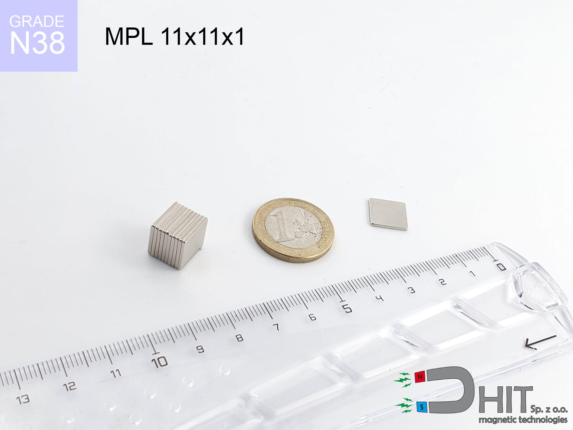
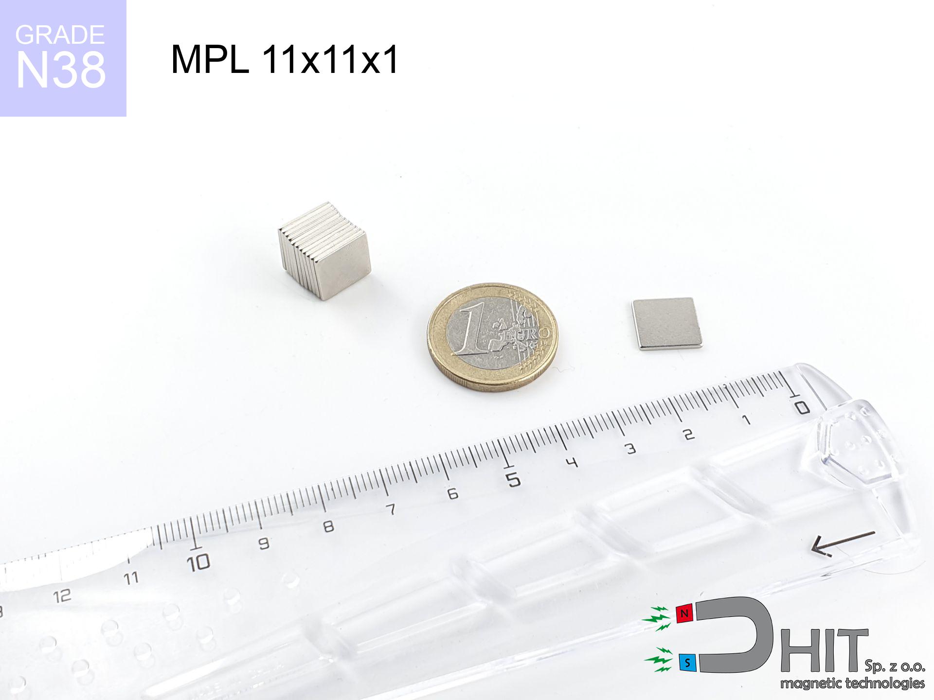
MPL 11x11x1 / N38 - lamellar magnet
lamellar magnet
Catalog no 020116
GTIN/EAN: 5906301811220
length
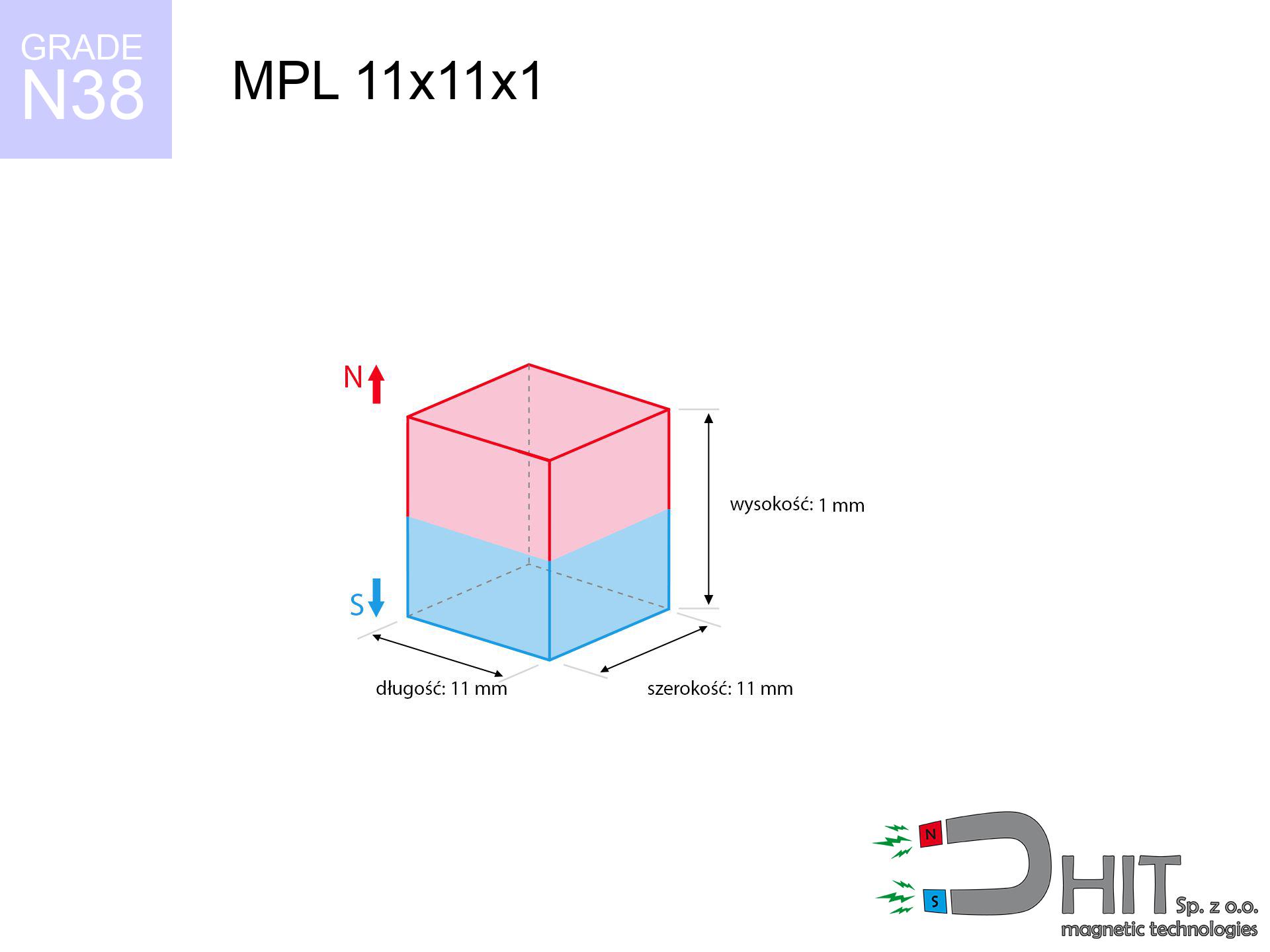
11 mm [±0,1 mm]
Width
11 mm [±0,1 mm]
Height
1 mm [±0,1 mm]
Weight
0.91 g
Magnetization Direction
↑ axial
Load capacity
0.43 kg / 4.24 N
Magnetic Induction
100.10 mT / 1001 Gs
Coating
[NiCuNi] Nickel
0.873 ZŁ with VAT / pcs + price for transport
0.710 ZŁ net + 23% VAT / pcs
bulk discounts:
Need more?Engineering report for this magnet
Full PDF analysis: pull and shear force, effect of distance, temperature and plate thickness, safety distances and the demagnetization curve.
Give us a call
+48 888 99 98 98
alternatively drop us a message by means of
inquiry form
the contact section.
Strength as well as shape of a neodymium magnet can be verified using our
magnetic calculator.
Same-day shipping for orders placed before 14:00.
Physical properties - MPL 11x11x1 / N38 - lamellar magnet
Specification / characteristics - MPL 11x11x1 / N38 - lamellar magnet
| properties | values |
|---|---|
| Cat. no. | 020116 |
| GTIN/EAN | 5906301811220 |
| Production/Distribution | Dhit sp. z o.o. |
| Country of origin | Poland / China / Germany |
| Customs code | 85059029 |
| length | 11 mm [±0,1 mm] |
| Width | 11 mm [±0,1 mm] |
| Height | 1 mm [±0,1 mm] |
| Weight | 0.91 g |
| Magnetization Direction | ↑ axial |
| Load capacity ~ ? | 0.43 kg / 4.24 N |
| Magnetic Induction ~ ? | 100.10 mT / 1001 Gs |
| Coating | [NiCuNi] Nickel |
| Manufacturing Tolerance | ±0.1 mm |
Magnetic properties of material N38
| properties | values | units |
|---|---|---|
| remenance Br [min. - max.] ? | 12.2-12.6 | kGs |
| remenance Br [min. - max.] ? | 1220-1260 | mT |
| coercivity bHc ? | 10.8-11.5 | kOe |
| coercivity bHc ? | 860-915 | kA/m |
| actual internal force iHc | ≥ 12 | kOe |
| actual internal force iHc | ≥ 955 | kA/m |
| energy density [min. - max.] ? | 36-38 | BH max MGOe |
| energy density [min. - max.] ? | 287-303 | BH max KJ/m |
| max. temperature ? | ≤ 80 | °C |
Physical properties of sintered neodymium magnets Nd2Fe14B at 20°C
| properties | values | units |
|---|---|---|
| Vickers hardness | ≥550 | Hv |
| Density | ≥7.4 | g/cm3 |
| Curie Temperature TC | 312 - 380 | °C |
| Curie Temperature TF | 593 - 716 | °F |
| Specific resistance | 150 | μΩ⋅cm |
| Bending strength | 250 | MPa |
| Compressive strength | 1000~1100 | MPa |
| Thermal expansion parallel (∥) to orientation (M) | (3-4) x 10-6 | °C-1 |
| Thermal expansion perpendicular (⊥) to orientation (M) | -(1-3) x 10-6 | °C-1 |
| Young's modulus | 1.7 x 10⁴ | kg/mm² |
Technical modeling of the assembly - technical parameters
Presented values represent the direct effect of a mathematical simulation. Results are based on models for the class Nd2Fe14B. Operational performance may differ from theoretical values. Please consider these data as a preliminary roadmap when designing systems.
Table 1: Static force (force vs distance) - power drop
MPL 11x11x1 / N38
| Distance (mm) | Induction (Gauss) / mT | Pull Force (kg/lbs/g/N) | Risk Status |
|---|---|---|---|
| 0 mm |
1001 Gs
100.1 mT
|
0.43 kg / 0.95 LBS
430.0 g / 4.2 N
|
weak grip |
| 1 mm |
925 Gs
92.5 mT
|
0.37 kg / 0.81 LBS
367.7 g / 3.6 N
|
weak grip |
| 2 mm |
800 Gs
80.0 mT
|
0.27 kg / 0.61 LBS
274.9 g / 2.7 N
|
weak grip |
| 3 mm |
659 Gs
65.9 mT
|
0.19 kg / 0.41 LBS
186.5 g / 1.8 N
|
weak grip |
| 5 mm |
415 Gs
41.5 mT
|
0.07 kg / 0.16 LBS
74.0 g / 0.7 N
|
weak grip |
| 10 mm |
130 Gs
13.0 mT
|
0.01 kg / 0.02 LBS
7.3 g / 0.1 N
|
weak grip |
| 15 mm |
51 Gs
5.1 mT
|
0.00 kg / 0.00 LBS
1.1 g / 0.0 N
|
weak grip |
| 20 mm |
24 Gs
2.4 mT
|
0.00 kg / 0.00 LBS
0.3 g / 0.0 N
|
weak grip |
| 30 mm |
8 Gs
0.8 mT
|
0.00 kg / 0.00 LBS
0.0 g / 0.0 N
|
weak grip |
| 50 mm |
2 Gs
0.2 mT
|
0.00 kg / 0.00 LBS
0.0 g / 0.0 N
|
weak grip |
Table 2: Shear capacity (vertical surface)
MPL 11x11x1 / N38
| Distance (mm) | Friction coefficient | Pull Force (kg/lbs/g/N) |
|---|---|---|
| 0 mm | Stal (~0.2) |
0.09 kg / 0.19 LBS
86.0 g / 0.8 N
|
| 1 mm | Stal (~0.2) |
0.07 kg / 0.16 LBS
74.0 g / 0.7 N
|
| 2 mm | Stal (~0.2) |
0.05 kg / 0.12 LBS
54.0 g / 0.5 N
|
| 3 mm | Stal (~0.2) |
0.04 kg / 0.08 LBS
38.0 g / 0.4 N
|
| 5 mm | Stal (~0.2) |
0.01 kg / 0.03 LBS
14.0 g / 0.1 N
|
| 10 mm | Stal (~0.2) |
0.00 kg / 0.00 LBS
2.0 g / 0.0 N
|
| 15 mm | Stal (~0.2) |
0.00 kg / 0.00 LBS
0.0 g / 0.0 N
|
| 20 mm | Stal (~0.2) |
0.00 kg / 0.00 LBS
0.0 g / 0.0 N
|
| 30 mm | Stal (~0.2) |
0.00 kg / 0.00 LBS
0.0 g / 0.0 N
|
| 50 mm | Stal (~0.2) |
0.00 kg / 0.00 LBS
0.0 g / 0.0 N
|
Table 3: Wall mounting (sliding) - behavior on slippery surfaces
MPL 11x11x1 / N38
| Surface type | Friction coefficient / % Mocy | Max load (kg/lbs/g/N) |
|---|---|---|
| Raw steel |
µ = 0.3
30% Nominalnej Siły
|
0.13 kg / 0.28 LBS
129.0 g / 1.3 N
|
| Painted steel (standard) |
µ = 0.2
20% Nominalnej Siły
|
0.09 kg / 0.19 LBS
86.0 g / 0.8 N
|
| Oily/slippery steel |
µ = 0.1
10% Nominalnej Siły
|
0.04 kg / 0.09 LBS
43.0 g / 0.4 N
|
| Magnet with anti-slip rubber |
µ = 0.5
50% Nominalnej Siły
|
0.22 kg / 0.47 LBS
215.0 g / 2.1 N
|
Table 4: Material efficiency (saturation) - sheet metal selection
MPL 11x11x1 / N38
| Steel thickness (mm) | % power | Real pull force (kg/lbs/g/N) |
|---|---|---|
| 0.5 mm |
|
0.04 kg / 0.09 LBS
43.0 g / 0.4 N
|
| 1 mm |
|
0.11 kg / 0.24 LBS
107.5 g / 1.1 N
|
| 2 mm |
|
0.22 kg / 0.47 LBS
215.0 g / 2.1 N
|
| 3 mm |
|
0.32 kg / 0.71 LBS
322.5 g / 3.2 N
|
| 5 mm |
|
0.43 kg / 0.95 LBS
430.0 g / 4.2 N
|
| 10 mm |
|
0.43 kg / 0.95 LBS
430.0 g / 4.2 N
|
| 11 mm |
|
0.43 kg / 0.95 LBS
430.0 g / 4.2 N
|
| 12 mm |
|
0.43 kg / 0.95 LBS
430.0 g / 4.2 N
|
Table 5: Thermal stability (stability) - power drop
MPL 11x11x1 / N38
| Ambient temp. (°C) | Power loss | Remaining pull (kg/lbs/g/N) | Status |
|---|---|---|---|
| 20 °C | 0.0% |
0.43 kg / 0.95 LBS
430.0 g / 4.2 N
|
OK |
| 40 °C | -2.2% |
0.42 kg / 0.93 LBS
420.5 g / 4.1 N
|
OK |
| 60 °C | -4.4% |
0.41 kg / 0.91 LBS
411.1 g / 4.0 N
|
|
| 80 °C | -6.6% |
0.40 kg / 0.89 LBS
401.6 g / 3.9 N
|
|
| 100 °C | -28.8% |
0.31 kg / 0.67 LBS
306.2 g / 3.0 N
|
Table 6: Two magnets (attraction) - forces in the system
MPL 11x11x1 / N38
| Gap (mm) | Attraction (kg/lbs) (N-S) | Shear Force (kg/lbs/g/N) | Repulsion (kg/lbs) (N-N) |
|---|---|---|---|
| 0 mm |
0.75 kg / 1.65 LBS
1 925 Gs
|
0.11 kg / 0.25 LBS
112 g / 1.1 N
|
N/A |
| 1 mm |
0.70 kg / 1.55 LBS
1 943 Gs
|
0.11 kg / 0.23 LBS
106 g / 1.0 N
|
0.63 kg / 1.40 LBS
~0 Gs
|
| 2 mm |
0.64 kg / 1.41 LBS
1 851 Gs
|
0.10 kg / 0.21 LBS
96 g / 0.9 N
|
0.58 kg / 1.27 LBS
~0 Gs
|
| 3 mm |
0.56 kg / 1.24 LBS
1 734 Gs
|
0.08 kg / 0.19 LBS
84 g / 0.8 N
|
0.50 kg / 1.11 LBS
~0 Gs
|
| 5 mm |
0.40 kg / 0.88 LBS
1 460 Gs
|
0.06 kg / 0.13 LBS
60 g / 0.6 N
|
0.36 kg / 0.79 LBS
~0 Gs
|
| 10 mm |
0.13 kg / 0.28 LBS
831 Gs
|
0.02 kg / 0.04 LBS
19 g / 0.2 N
|
0.12 kg / 0.26 LBS
~0 Gs
|
| 20 mm |
0.01 kg / 0.03 LBS
261 Gs
|
0.00 kg / 0.00 LBS
2 g / 0.0 N
|
0.01 kg / 0.03 LBS
~0 Gs
|
| 50 mm |
0.00 kg / 0.00 LBS
26 Gs
|
0.00 kg / 0.00 LBS
0 g / 0.0 N
|
0.00 kg / 0.00 LBS
~0 Gs
|
| 60 mm |
0.00 kg / 0.00 LBS
16 Gs
|
0.00 kg / 0.00 LBS
0 g / 0.0 N
|
0.00 kg / 0.00 LBS
~0 Gs
|
| 70 mm |
0.00 kg / 0.00 LBS
10 Gs
|
0.00 kg / 0.00 LBS
0 g / 0.0 N
|
0.00 kg / 0.00 LBS
~0 Gs
|
| 80 mm |
0.00 kg / 0.00 LBS
7 Gs
|
0.00 kg / 0.00 LBS
0 g / 0.0 N
|
0.00 kg / 0.00 LBS
~0 Gs
|
| 90 mm |
0.00 kg / 0.00 LBS
5 Gs
|
0.00 kg / 0.00 LBS
0 g / 0.0 N
|
0.00 kg / 0.00 LBS
~0 Gs
|
| 100 mm |
0.00 kg / 0.00 LBS
4 Gs
|
0.00 kg / 0.00 LBS
0 g / 0.0 N
|
0.00 kg / 0.00 LBS
~0 Gs
|
Table 7: Protective zones (implants) - precautionary measures
MPL 11x11x1 / N38
| Object / Device | Limit (Gauss) / mT | Safe distance |
|---|---|---|
| Pacemaker | 5 Gs (0.5 mT) | 4.0 cm |
| Hearing aid | 10 Gs (1.0 mT) | 3.0 cm |
| Mechanical watch | 20 Gs (2.0 mT) | 2.5 cm |
| Phone / Smartphone | 40 Gs (4.0 mT) | 2.0 cm |
| Car key | 50 Gs (5.0 mT) | 2.0 cm |
| Payment card | 400 Gs (40.0 mT) | 1.0 cm |
| HDD hard drive | 600 Gs (60.0 mT) | 0.5 cm |
Table 8: Dynamics (kinetic energy) - collision effects
MPL 11x11x1 / N38
| Start from (mm) | Speed (km/h) | Energy (J) | Predicted outcome |
|---|---|---|---|
| 10 mm |
19.50 km/h
(5.42 m/s)
|
0.01 J | |
| 30 mm |
19.63 km/h
(5.45 m/s)
|
0.01 J | |
| 50 mm |
19.57 km/h
(5.44 m/s)
|
0.01 J | |
| 100 mm |
19.65 km/h
(5.46 m/s)
|
0.01 J |
Table 9: Corrosion resistance
MPL 11x11x1 / N38
| Technical parameter | Value / Description |
|---|---|
| Coating type | [NiCuNi] Nickel |
| Layer structure | Nickel - Copper - Nickel |
| Layer thickness | 10-20 µm |
| Salt spray test (SST) ? | 24 h |
| Recommended environment | Indoors only (dry) |
Table 10: Construction data (Flux)
MPL 11x11x1 / N38
| Parameter | Value | SI Unit / Description |
|---|---|---|
| Magnetic Flux | 1 627 Mx | 16.3 µWb |
| Pc Coefficient | 0.13 | Low (Flat) |
Table 11: Underwater work (magnet fishing)
MPL 11x11x1 / N38
| Environment | Effective steel pull | Effect |
|---|---|---|
| Air (land) | 0.43 kg | Standard |
| Water (riverbed) |
0.49 kg
(+0.06 kg buoyancy gain)
|
+14.5% |
1. Wall mount (shear)
*Note: On a vertical wall, the magnet holds only approx. 20-30% of its max power.
2. Efficiency vs thickness
*Thin steel (e.g. 0.5mm PC case) significantly weakens the holding force.
3. Heat tolerance
*For N38 grade, the safety limit is 80°C.
4. Demagnetization curve and operating point (B-H)
chart generated for the permeance coefficient Pc (Permeance Coefficient) = 0.13
The chart above illustrates the magnetic characteristics of the material within the second quadrant of the hysteresis loop. The solid red line represents the demagnetization curve (material potential), while the dashed blue line is the load line based on the magnet's geometry. The Pc (Permeance Coefficient), also known as the load line slope, is a dimensionless value that describes the relationship between the magnet's shape and its magnetic stability. The intersection of these two lines (the black dot) is the operating point — it determines the actual magnetic flux density generated by the magnet in this specific configuration. A higher Pc value means the magnet is more 'slender' (tall relative to its area), resulting in a higher operating point and better resistance to irreversible demagnetization caused by external fields or temperature. A value of 0.42 is relatively low (typical for flat magnets), meaning the operating point is closer to the 'knee' of the curve — caution is advised when operating at temperatures near the maximum limit to avoid strength loss.
Elemental analysis
| iron (Fe) | 64% – 68% |
| neodymium (Nd) | 29% – 32% |
| boron (B) | 1.1% – 1.2% |
| dysprosium (Dy) | 0.5% – 2.0% |
| coating (Ni-Cu-Ni) | < 0.05% |
Environmental data
| recyclability (EoL) | 100% |
| recycled raw materials | ~10% (pre-cons) |
| carbon footprint | low / zredukowany |
| waste code (EWC) | 16 02 16 |
Other proposals


![UI 45x13x6 [Z323] / N38 - badge holder](https://cdn3.dhit.pl/graphics/products/ui45x13x6-z323-fap.jpg "UI 45x13x6 [Z323] / N38 - badge holder")
Strengths and weaknesses of rare earth magnets.
Benefits
- They have constant strength, and over nearly ten years their attraction force decreases symbolically – ~1% (according to theory),
- They feature excellent resistance to weakening of magnetic properties due to external magnetic sources,
- A magnet with a shiny gold surface is more attractive,
- They are known for high magnetic induction at the operating surface, which affects their effectiveness,
- Made from properly selected components, these magnets show impressive resistance to high heat, enabling them to function (depending on their shape) at temperatures up to 230°C and above...
- Thanks to flexibility in shaping and the capacity to customize to unusual requirements,
- Wide application in future technologies – they serve a role in mass storage devices, electromotive mechanisms, advanced medical instruments, and multitasking production systems.
- Relatively small size with high pulling force – neodymium magnets offer impressive pulling force in compact dimensions, which allows their use in miniature devices
Disadvantages
- At very strong impacts they can crack, therefore we recommend placing them in strong housings. A metal housing provides additional protection against damage, as well as increases the magnet's durability.
- When exposed to high temperature, neodymium magnets experience a drop in strength. Often, when the temperature exceeds 80°C, their strength decreases (depending on the size, as well as shape of the magnet). For those who need magnets for extreme conditions, we offer [AH] versions withstanding up to 230°C
- They oxidize in a humid environment - during use outdoors we suggest using waterproof magnets e.g. in rubber, plastic
- Limited possibility of producing nuts in the magnet and complicated forms - preferred is casing - mounting mechanism.
- Health risk resulting from small fragments of magnets are risky, in case of ingestion, which gains importance in the context of child safety. Additionally, small elements of these products can complicate diagnosis medical when they are in the body.
- High unit price – neodymium magnets are more expensive than other types of magnets (e.g. ferrite), which hinders application in large quantities
Pull force analysis
Maximum magnetic pulling force – what it depends on?
- on a plate made of structural steel, perfectly concentrating the magnetic field
- with a thickness no less than 10 mm
- with a surface perfectly flat
- without any insulating layer between the magnet and steel
- during pulling in a direction perpendicular to the plane
- in temp. approx. 20°C
Practical lifting capacity: influencing factors
- Distance – existence of foreign body (paint, dirt, gap) acts as an insulator, which reduces power rapidly (even by 50% at 0.5 mm).
- Load vector – maximum parameter is obtained only during perpendicular pulling. The force required to slide of the magnet along the surface is usually several times lower (approx. 1/5 of the lifting capacity).
- Base massiveness – insufficiently thick sheet causes magnetic saturation, causing part of the power to be wasted into the air.
- Material composition – different alloys reacts the same. Alloy additives weaken the interaction with the magnet.
- Surface quality – the smoother and more polished the surface, the larger the contact zone and higher the lifting capacity. Roughness acts like micro-gaps.
- Operating temperature – neodymium magnets have a negative temperature coefficient. At higher temperatures they are weaker, and in frost gain strength (up to a certain limit).
Lifting capacity was assessed by applying a smooth steel plate of optimal thickness (min. 20 mm), under perpendicular pulling force, however under parallel forces the load capacity is reduced by as much as 75%. Additionally, even a slight gap between the magnet’s surface and the plate reduces the lifting capacity.
H&S for magnets
Medical interference
Patients with a heart stimulator must keep an large gap from magnets. The magnetism can interfere with the functioning of the implant.
Sensitization to coating
Warning for allergy sufferers: The nickel-copper-nickel coating contains nickel. If redness occurs, cease handling magnets and use protective gear.
Cards and drives
Avoid bringing magnets close to a purse, laptop, or TV. The magnetism can irreversibly ruin these devices and wipe information from cards.
Compass and GPS
Navigation devices and smartphones are highly susceptible to magnetism. Close proximity with a strong magnet can permanently damage the internal compass in your phone.
Magnet fragility
Despite the nickel coating, the material is delicate and not impact-resistant. Do not hit, as the magnet may crumble into sharp, dangerous pieces.
Respect the power
Use magnets consciously. Their huge power can shock even experienced users. Plan your moves and do not underestimate their power.
Heat sensitivity
Avoid heat. Neodymium magnets are susceptible to heat. If you require operation above 80°C, inquire about special high-temperature series (H, SH, UH).
Choking Hazard
Neodymium magnets are not toys. Accidental ingestion of a few magnets can lead to them connecting inside the digestive tract, which constitutes a direct threat to life and necessitates urgent medical intervention.
Crushing force
Protect your hands. Two large magnets will join instantly with a force of massive weight, crushing anything in their path. Exercise extreme caution!
Combustion hazard
Dust created during grinding of magnets is combustible. Avoid drilling into magnets unless you are an expert.
Tabela kosztu i czasu dostawy
Płatność przed wysyłką:

GLS kurier
Przesyłka będzie u Ciebie za 2-3 dni
14.99 ZŁ

InPost Paczkomaty 24/7
Przesyłka będzie u Ciebie za 1-2 dni
12.30 ZŁ
Płatność przy odbiorze (pobranie):
GLS kurier
Przesyłka będzie u Ciebie za 1-2 dni
23.00 ZŁ
Rate the product
Your rating