
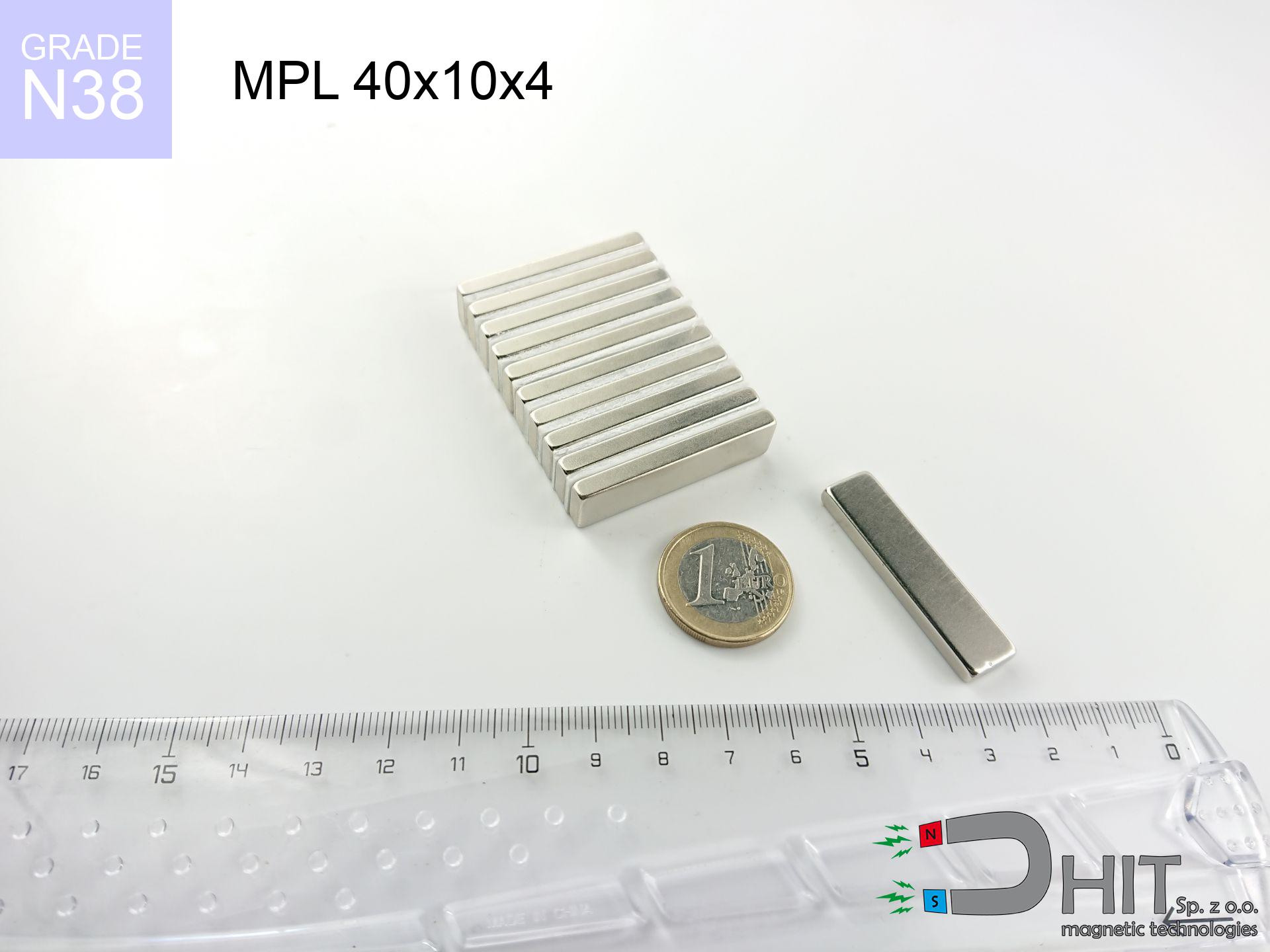
MPL 40x10x4 / N38 - lamellar magnet
lamellar magnet
Catalog no 020150
GTIN/EAN: 5906301811565
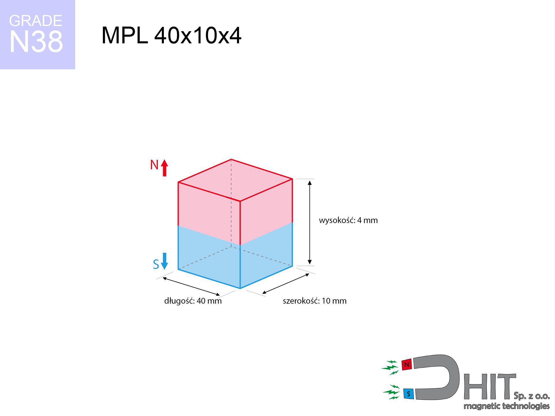
length
40 mm [±0,1 mm]
Width
10 mm [±0,1 mm]
Height
4 mm [±0,1 mm]
Weight
12 g
Magnetization Direction
↑ axial
Load capacity
9.31 kg / 91.33 N
Magnetic Induction
275.57 mT / 2756 Gs
Coating
[NiCuNi] Nickel
4.87 ZŁ with VAT / pcs + price for transport
3.96 ZŁ net + 23% VAT / pcs
bulk discounts:
Need more?Engineering report for this magnet
Full PDF analysis: pull and shear force, effect of distance, temperature and plate thickness, safety distances and the demagnetization curve.
Pick up the phone and ask
+48 22 499 98 98
if you prefer get in touch via
our online form
the contact page.
Force as well as shape of a neodymium magnet can be tested with our
our magnetic calculator.
Order by 14:00 and we’ll ship today!
Technical details - MPL 40x10x4 / N38 - lamellar magnet
Specification / characteristics - MPL 40x10x4 / N38 - lamellar magnet
| properties | values |
|---|---|
| Cat. no. | 020150 |
| GTIN/EAN | 5906301811565 |
| Production/Distribution | Dhit sp. z o.o. |
| Country of origin | Poland / China / Germany |
| Customs code | 85059029 |
| length | 40 mm [±0,1 mm] |
| Width | 10 mm [±0,1 mm] |
| Height | 4 mm [±0,1 mm] |
| Weight | 12 g |
| Magnetization Direction | ↑ axial |
| Load capacity ~ ? | 9.31 kg / 91.33 N |
| Magnetic Induction ~ ? | 275.57 mT / 2756 Gs |
| Coating | [NiCuNi] Nickel |
| Manufacturing Tolerance | ±0.1 mm |
Magnetic properties of material N38
| properties | values | units |
|---|---|---|
| remenance Br [min. - max.] ? | 12.2-12.6 | kGs |
| remenance Br [min. - max.] ? | 1220-1260 | mT |
| coercivity bHc ? | 10.8-11.5 | kOe |
| coercivity bHc ? | 860-915 | kA/m |
| actual internal force iHc | ≥ 12 | kOe |
| actual internal force iHc | ≥ 955 | kA/m |
| energy density [min. - max.] ? | 36-38 | BH max MGOe |
| energy density [min. - max.] ? | 287-303 | BH max KJ/m |
| max. temperature ? | ≤ 80 | °C |
Physical properties of sintered neodymium magnets Nd2Fe14B at 20°C
| properties | values | units |
|---|---|---|
| Vickers hardness | ≥550 | Hv |
| Density | ≥7.4 | g/cm3 |
| Curie Temperature TC | 312 - 380 | °C |
| Curie Temperature TF | 593 - 716 | °F |
| Specific resistance | 150 | μΩ⋅cm |
| Bending strength | 250 | MPa |
| Compressive strength | 1000~1100 | MPa |
| Thermal expansion parallel (∥) to orientation (M) | (3-4) x 10-6 | °C-1 |
| Thermal expansion perpendicular (⊥) to orientation (M) | -(1-3) x 10-6 | °C-1 |
| Young's modulus | 1.7 x 10⁴ | kg/mm² |
Physical simulation of the assembly - report
These data constitute the direct effect of a mathematical analysis. Values were calculated on models for the material Nd2Fe14B. Operational parameters may differ. Treat these data as a preliminary roadmap when designing systems.
Table 1: Static force (pull vs gap) - interaction chart
MPL 40x10x4 / N38
| Distance (mm) | Induction (Gauss) / mT | Pull Force (kg/lbs/g/N) | Risk Status |
|---|---|---|---|
| 0 mm |
2755 Gs
275.5 mT
|
9.31 kg / 20.53 lbs
9310.0 g / 91.3 N
|
strong |
| 1 mm |
2413 Gs
241.3 mT
|
7.14 kg / 15.75 lbs
7143.1 g / 70.1 N
|
strong |
| 2 mm |
2044 Gs
204.4 mT
|
5.13 kg / 11.31 lbs
5128.9 g / 50.3 N
|
strong |
| 3 mm |
1703 Gs
170.3 mT
|
3.56 kg / 7.85 lbs
3559.5 g / 34.9 N
|
strong |
| 5 mm |
1173 Gs
117.3 mT
|
1.69 kg / 3.72 lbs
1688.2 g / 16.6 N
|
safe |
| 10 mm |
522 Gs
52.2 mT
|
0.33 kg / 0.74 lbs
334.9 g / 3.3 N
|
safe |
| 15 mm |
277 Gs
27.7 mT
|
0.09 kg / 0.21 lbs
94.2 g / 0.9 N
|
safe |
| 20 mm |
163 Gs
16.3 mT
|
0.03 kg / 0.07 lbs
32.8 g / 0.3 N
|
safe |
| 30 mm |
69 Gs
6.9 mT
|
0.01 kg / 0.01 lbs
5.8 g / 0.1 N
|
safe |
| 50 mm |
19 Gs
1.9 mT
|
0.00 kg / 0.00 lbs
0.5 g / 0.0 N
|
safe |
Table 2: Vertical force (vertical surface)
MPL 40x10x4 / N38
| Distance (mm) | Friction coefficient | Pull Force (kg/lbs/g/N) |
|---|---|---|
| 0 mm | Stal (~0.2) |
1.86 kg / 4.11 lbs
1862.0 g / 18.3 N
|
| 1 mm | Stal (~0.2) |
1.43 kg / 3.15 lbs
1428.0 g / 14.0 N
|
| 2 mm | Stal (~0.2) |
1.03 kg / 2.26 lbs
1026.0 g / 10.1 N
|
| 3 mm | Stal (~0.2) |
0.71 kg / 1.57 lbs
712.0 g / 7.0 N
|
| 5 mm | Stal (~0.2) |
0.34 kg / 0.75 lbs
338.0 g / 3.3 N
|
| 10 mm | Stal (~0.2) |
0.07 kg / 0.15 lbs
66.0 g / 0.6 N
|
| 15 mm | Stal (~0.2) |
0.02 kg / 0.04 lbs
18.0 g / 0.2 N
|
| 20 mm | Stal (~0.2) |
0.01 kg / 0.01 lbs
6.0 g / 0.1 N
|
| 30 mm | Stal (~0.2) |
0.00 kg / 0.00 lbs
2.0 g / 0.0 N
|
| 50 mm | Stal (~0.2) |
0.00 kg / 0.00 lbs
0.0 g / 0.0 N
|
Table 3: Wall mounting (sliding) - vertical pull
MPL 40x10x4 / N38
| Surface type | Friction coefficient / % Mocy | Max load (kg/lbs/g/N) |
|---|---|---|
| Raw steel |
µ = 0.3
30% Nominalnej Siły
|
2.79 kg / 6.16 lbs
2793.0 g / 27.4 N
|
| Painted steel (standard) |
µ = 0.2
20% Nominalnej Siły
|
1.86 kg / 4.11 lbs
1862.0 g / 18.3 N
|
| Oily/slippery steel |
µ = 0.1
10% Nominalnej Siły
|
0.93 kg / 2.05 lbs
931.0 g / 9.1 N
|
| Magnet with anti-slip rubber |
µ = 0.5
50% Nominalnej Siły
|
4.66 kg / 10.26 lbs
4655.0 g / 45.7 N
|
Table 4: Material efficiency (saturation) - sheet metal selection
MPL 40x10x4 / N38
| Steel thickness (mm) | % power | Real pull force (kg/lbs/g/N) |
|---|---|---|
| 0.5 mm |
|
0.93 kg / 2.05 lbs
931.0 g / 9.1 N
|
| 1 mm |
|
2.33 kg / 5.13 lbs
2327.5 g / 22.8 N
|
| 2 mm |
|
4.66 kg / 10.26 lbs
4655.0 g / 45.7 N
|
| 3 mm |
|
6.98 kg / 15.39 lbs
6982.5 g / 68.5 N
|
| 5 mm |
|
9.31 kg / 20.53 lbs
9310.0 g / 91.3 N
|
| 10 mm |
|
9.31 kg / 20.53 lbs
9310.0 g / 91.3 N
|
| 11 mm |
|
9.31 kg / 20.53 lbs
9310.0 g / 91.3 N
|
| 12 mm |
|
9.31 kg / 20.53 lbs
9310.0 g / 91.3 N
|
Table 5: Thermal stability (material behavior) - thermal limit
MPL 40x10x4 / N38
| Ambient temp. (°C) | Power loss | Remaining pull (kg/lbs/g/N) | Status |
|---|---|---|---|
| 20 °C | 0.0% |
9.31 kg / 20.53 lbs
9310.0 g / 91.3 N
|
OK |
| 40 °C | -2.2% |
9.11 kg / 20.07 lbs
9105.2 g / 89.3 N
|
OK |
| 60 °C | -4.4% |
8.90 kg / 19.62 lbs
8900.4 g / 87.3 N
|
|
| 80 °C | -6.6% |
8.70 kg / 19.17 lbs
8695.5 g / 85.3 N
|
|
| 100 °C | -28.8% |
6.63 kg / 14.61 lbs
6628.7 g / 65.0 N
|
Table 6: Two magnets (attraction) - field range
MPL 40x10x4 / N38
| Gap (mm) | Attraction (kg/lbs) (N-S) | Shear Strength (kg/lbs/g/N) | Repulsion (kg/lbs) (N-N) |
|---|---|---|---|
| 0 mm |
18.71 kg / 41.25 lbs
4 164 Gs
|
2.81 kg / 6.19 lbs
2807 g / 27.5 N
|
N/A |
| 1 mm |
16.57 kg / 36.53 lbs
5 185 Gs
|
2.49 kg / 5.48 lbs
2486 g / 24.4 N
|
14.91 kg / 32.88 lbs
~0 Gs
|
| 2 mm |
14.36 kg / 31.65 lbs
4 826 Gs
|
2.15 kg / 4.75 lbs
2153 g / 21.1 N
|
12.92 kg / 28.48 lbs
~0 Gs
|
| 3 mm |
12.24 kg / 26.98 lbs
4 455 Gs
|
1.84 kg / 4.05 lbs
1836 g / 18.0 N
|
11.01 kg / 24.28 lbs
~0 Gs
|
| 5 mm |
8.61 kg / 18.98 lbs
3 737 Gs
|
1.29 kg / 2.85 lbs
1291 g / 12.7 N
|
7.75 kg / 17.08 lbs
~0 Gs
|
| 10 mm |
3.39 kg / 7.48 lbs
2 346 Gs
|
0.51 kg / 1.12 lbs
509 g / 5.0 N
|
3.05 kg / 6.73 lbs
~0 Gs
|
| 20 mm |
0.67 kg / 1.48 lbs
1 045 Gs
|
0.10 kg / 0.22 lbs
101 g / 1.0 N
|
0.61 kg / 1.34 lbs
~0 Gs
|
| 50 mm |
0.03 kg / 0.06 lbs
207 Gs
|
0.00 kg / 0.01 lbs
4 g / 0.0 N
|
0.02 kg / 0.05 lbs
~0 Gs
|
| 60 mm |
0.01 kg / 0.03 lbs
138 Gs
|
0.00 kg / 0.00 lbs
2 g / 0.0 N
|
0.01 kg / 0.02 lbs
~0 Gs
|
| 70 mm |
0.01 kg / 0.01 lbs
96 Gs
|
0.00 kg / 0.00 lbs
1 g / 0.0 N
|
0.00 kg / 0.00 lbs
~0 Gs
|
| 80 mm |
0.00 kg / 0.01 lbs
69 Gs
|
0.00 kg / 0.00 lbs
0 g / 0.0 N
|
0.00 kg / 0.00 lbs
~0 Gs
|
| 90 mm |
0.00 kg / 0.00 lbs
51 Gs
|
0.00 kg / 0.00 lbs
0 g / 0.0 N
|
0.00 kg / 0.00 lbs
~0 Gs
|
| 100 mm |
0.00 kg / 0.00 lbs
39 Gs
|
0.00 kg / 0.00 lbs
0 g / 0.0 N
|
0.00 kg / 0.00 lbs
~0 Gs
|
Table 7: Hazards (electronics) - warnings
MPL 40x10x4 / N38
| Object / Device | Limit (Gauss) / mT | Safe distance |
|---|---|---|
| Pacemaker | 5 Gs (0.5 mT) | 8.5 cm |
| Hearing aid | 10 Gs (1.0 mT) | 6.5 cm |
| Timepiece | 20 Gs (2.0 mT) | 5.0 cm |
| Phone / Smartphone | 40 Gs (4.0 mT) | 4.0 cm |
| Car key | 50 Gs (5.0 mT) | 3.5 cm |
| Payment card | 400 Gs (40.0 mT) | 1.5 cm |
| HDD hard drive | 600 Gs (60.0 mT) | 1.0 cm |
Table 8: Impact energy (cracking risk) - collision effects
MPL 40x10x4 / N38
| Start from (mm) | Speed (km/h) | Energy (J) | Predicted outcome |
|---|---|---|---|
| 10 mm |
28.72 km/h
(7.98 m/s)
|
0.38 J | |
| 30 mm |
48.67 km/h
(13.52 m/s)
|
1.10 J | |
| 50 mm |
62.82 km/h
(17.45 m/s)
|
1.83 J | |
| 100 mm |
88.83 km/h
(24.68 m/s)
|
3.65 J |
Table 9: Surface protection spec
MPL 40x10x4 / N38
| Technical parameter | Value / Description |
|---|---|
| Coating type | [NiCuNi] Nickel |
| Layer structure | Nickel - Copper - Nickel |
| Layer thickness | 10-20 µm |
| Salt spray test (SST) ? | 24 h |
| Recommended environment | Indoors only (dry) |
Table 10: Electrical data (Pc)
MPL 40x10x4 / N38
| Parameter | Value | SI Unit / Description |
|---|---|---|
| Magnetic Flux | 9 840 Mx | 98.4 µWb |
| Pc Coefficient | 0.26 | Low (Flat) |
Table 11: Submerged application
MPL 40x10x4 / N38
| Environment | Effective steel pull | Effect |
|---|---|---|
| Air (land) | 9.31 kg | Standard |
| Water (riverbed) |
10.66 kg
(+1.35 kg buoyancy gain)
|
+14.5% |
1. Sliding resistance
*Caution: On a vertical wall, the magnet retains just approx. 20-30% of its nominal pull.
2. Plate thickness effect
*Thin metal sheet (e.g. computer case) significantly limits the holding force.
3. Thermal stability
*For N38 grade, the max working temp is 80°C.
4. Demagnetization curve and operating point (B-H)
chart generated for the permeance coefficient Pc (Permeance Coefficient) = 0.26
This simulation demonstrates the magnetic stability of the selected magnet under specific geometric conditions. The solid red line represents the demagnetization curve (material potential), while the dashed blue line is the load line based on the magnet's geometry. The Pc (Permeance Coefficient), also known as the load line slope, is a dimensionless value that describes the relationship between the magnet's shape and its magnetic stability. The intersection of these two lines (the black dot) is the operating point — it determines the actual magnetic flux density generated by the magnet in this specific configuration. A higher Pc value means the magnet is more 'slender' (tall relative to its area), resulting in a higher operating point and better resistance to irreversible demagnetization caused by external fields or temperature. A value of 0.42 is relatively low (typical for flat magnets), meaning the operating point is closer to the 'knee' of the curve — caution is advised when operating at temperatures near the maximum limit to avoid strength loss.
Material specification
| iron (Fe) | 64% – 68% |
| neodymium (Nd) | 29% – 32% |
| boron (B) | 1.1% – 1.2% |
| dysprosium (Dy) | 0.5% – 2.0% |
| coating (Ni-Cu-Ni) | < 0.05% |
Ecology and recycling (GPSR)
| recyclability (EoL) | 100% |
| recycled raw materials | ~10% (pre-cons) |
| carbon footprint | low / zredukowany |
| waste code (EWC) | 16 02 16 |
Other products
![SM 32x300 [2xM8] / N42 - magnetic separator](https://cdn3.dhit.pl/graphics/products/sm-32x300-2xm8-pel.jpg "SM 32x300 [2xM8] / N42 - magnetic separator")
![SM 32x225 [2xM8] / N42 - magnetic separator](https://cdn3.dhit.pl/graphics/products/sm-32x225-2xm8-dob.jpg "SM 32x225 [2xM8] / N42 - magnetic separator")


Advantages and disadvantages of rare earth magnets.
Advantages
- They retain magnetic properties for around 10 years – the loss is just ~1% (based on simulations),
- Neodymium magnets are extremely resistant to demagnetization caused by magnetic disturbances,
- By applying a smooth layer of nickel, the element acquires an aesthetic look,
- Magnetic induction on the surface of the magnet is strong,
- Due to their durability and thermal resistance, neodymium magnets can operate (depending on the form) even at high temperatures reaching 230°C or more...
- Possibility of exact forming as well as modifying to specific conditions,
- Huge importance in future technologies – they are commonly used in HDD drives, brushless drives, precision medical tools, and multitasking production systems.
- Relatively small size with high pulling force – neodymium magnets offer impressive pulling force in tiny dimensions, which makes them useful in compact constructions
Cons
- Brittleness is one of their disadvantages. Upon strong impact they can fracture. We advise keeping them in a strong case, which not only secures them against impacts but also increases their durability
- Neodymium magnets decrease their power under the influence of heating. As soon as 80°C is exceeded, many of them start losing their force. Therefore, we recommend our special magnets marked [AH], which maintain stability even at temperatures up to 230°C
- When exposed to humidity, magnets usually rust. For applications outside, it is recommended to use protective magnets, such as those in rubber or plastics, which prevent oxidation as well as corrosion.
- We recommend a housing - magnetic holder, due to difficulties in producing threads inside the magnet and complicated shapes.
- Possible danger resulting from small fragments of magnets pose a threat, in case of ingestion, which becomes key in the aspect of protecting the youngest. Additionally, small elements of these devices are able to be problematic in diagnostics medical when they are in the body.
- Due to complex production process, their price exceeds standard values,
Holding force characteristics
Optimal lifting capacity of a neodymium magnet – what contributes to it?
- with the application of a yoke made of special test steel, guaranteeing full magnetic saturation
- with a thickness minimum 10 mm
- with an ideally smooth touching surface
- under conditions of ideal adhesion (surface-to-surface)
- for force applied at a right angle (in the magnet axis)
- in temp. approx. 20°C
Lifting capacity in real conditions – factors
- Distance (betwixt the magnet and the metal), because even a microscopic distance (e.g. 0.5 mm) leads to a reduction in lifting capacity by up to 50% (this also applies to paint, corrosion or dirt).
- Loading method – declared lifting capacity refers to detachment vertically. When slipping, the magnet exhibits significantly lower power (often approx. 20-30% of maximum force).
- Substrate thickness – to utilize 100% power, the steel must be adequately massive. Paper-thin metal restricts the lifting capacity (the magnet "punches through" it).
- Material type – the best choice is pure iron steel. Cast iron may generate lower lifting capacity.
- Base smoothness – the more even the plate, the larger the contact zone and stronger the hold. Roughness acts like micro-gaps.
- Thermal conditions – neodymium magnets have a sensitivity to temperature. At higher temperatures they are weaker, and in frost they can be stronger (up to a certain limit).
Holding force was checked on a smooth steel plate of 20 mm thickness, when the force acted perpendicularly, however under shearing force the lifting capacity is smaller. In addition, even a slight gap between the magnet’s surface and the plate reduces the load capacity.
Precautions when working with neodymium magnets
Fire risk
Dust produced during grinding of magnets is combustible. Avoid drilling into magnets without proper cooling and knowledge.
Bodily injuries
Pinching hazard: The pulling power is so immense that it can result in hematomas, pinching, and even bone fractures. Protective gloves are recommended.
Life threat
Life threat: Neodymium magnets can deactivate pacemakers and defibrillators. Do not approach if you have medical devices.
Material brittleness
Neodymium magnets are ceramic materials, which means they are prone to chipping. Collision of two magnets will cause them breaking into small pieces.
Electronic devices
Equipment safety: Strong magnets can damage data carriers and sensitive devices (heart implants, medical aids, mechanical watches).
Nickel allergy
Warning for allergy sufferers: The nickel-copper-nickel coating contains nickel. If skin irritation occurs, cease handling magnets and wear gloves.
Heat sensitivity
Standard neodymium magnets (N-type) lose power when the temperature exceeds 80°C. Damage is permanent.
Respect the power
Handle magnets with awareness. Their powerful strength can surprise even experienced users. Plan your moves and respect their power.
GPS Danger
An intense magnetic field negatively affects the functioning of compasses in phones and GPS navigation. Do not bring magnets near a smartphone to prevent breaking the sensors.
Danger to the youngest
NdFeB magnets are not suitable for play. Accidental ingestion of several magnets may result in them pinching intestinal walls, which constitutes a severe health hazard and requires urgent medical intervention.
Tabela kosztu i czasu dostawy
Płatność przed wysyłką:

GLS kurier
Przesyłka będzie u Ciebie za 2-3 dni
14.99 ZŁ

InPost Paczkomaty 24/7
Przesyłka będzie u Ciebie za 1-2 dni
12.30 ZŁ
Płatność przy odbiorze (pobranie):
GLS kurier
Przesyłka będzie u Ciebie za 1-2 dni
23.00 ZŁ
Rate the product
Your rating