

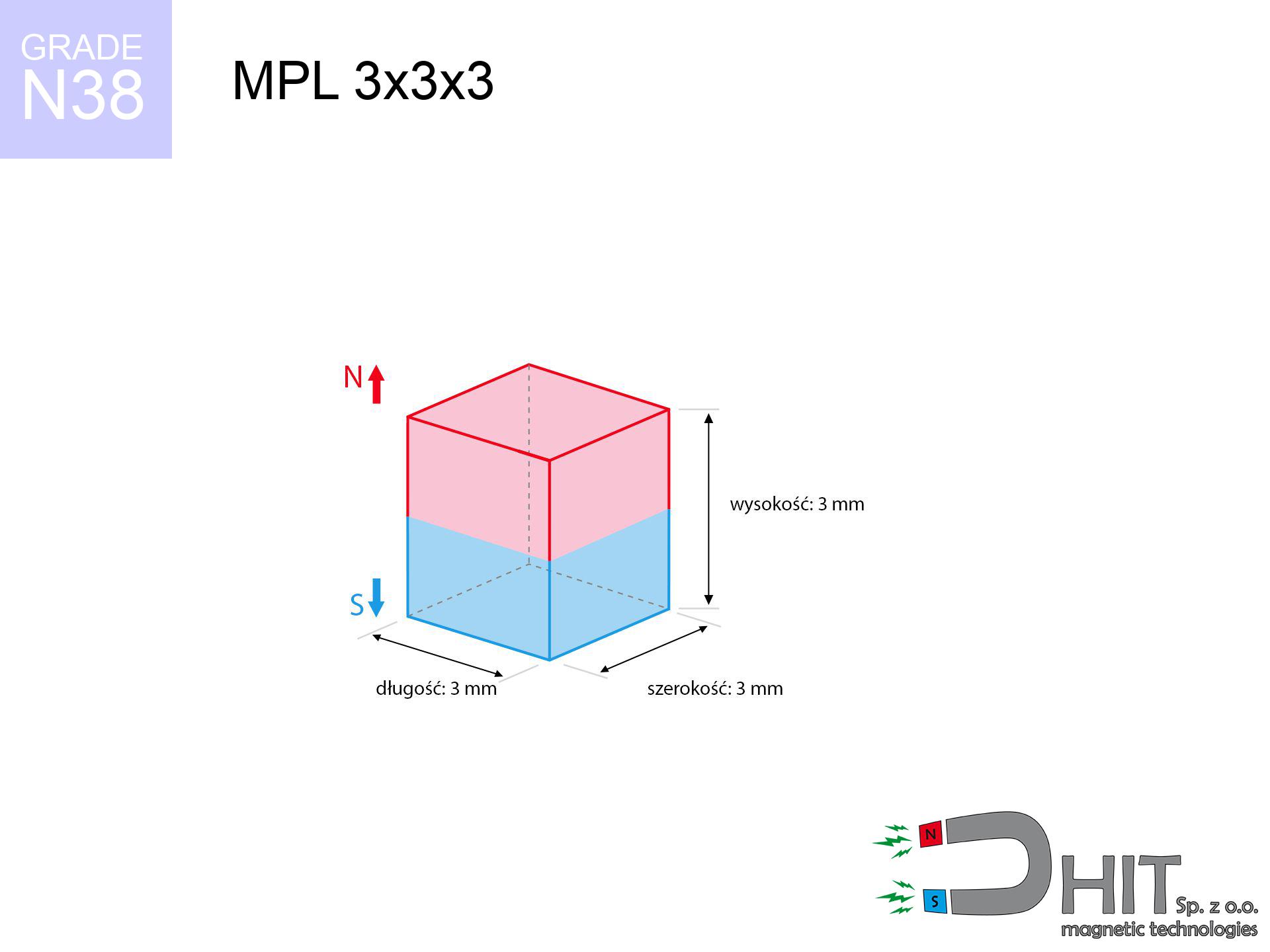
MPL 3x3x3 / N38 - lamellar magnet
lamellar magnet
Catalog no 020148
GTIN/EAN: 5906301811541
- length
- 3 mm [±0,1 mm]
- Width
- 3 mm [±0,1 mm]
- Height
- 3 mm [±0,1 mm]
- Weight
- 0.2 g
- Magnetization Direction
- ↑ axial
- Coating
- [NiCuNi] Nickel
0.1845 zł with VAT / pcs + price for transport
0.1500 zł net + 23% VAT / pcs
bulk discounts:
Need more?Engineering report for this magnet
Full PDF analysis: pull and shear force, effect of distance, temperature and plate thickness, safety distances and the demagnetization curve.
Give us a call
+48 888 99 98 98
alternatively send us a note by means of
inquiry form
through our site.
Weight and appearance of magnetic components can be analyzed with our
online calculation tool.
Order by 14:00 and we’ll ship today!
Technical - MPL 3x3x3 / N38 - lamellar magnet
Specification / characteristics - MPL 3x3x3 / N38 - lamellar magnet
| properties | values |
|---|---|
| Cat. no. | 020148 |
| GTIN/EAN | 5906301811541 |
| Production/Distribution | Dhit sp. z o.o. |
| Country of origin | Poland / China / Germany |
| Customs code | 85059029 |
| length | 3 mm [±0,1 mm] |
| Width | 3 mm [±0,1 mm] |
| Height | 3 mm [±0,1 mm] |
| Weight | 0.2 g |
| Magnetization Direction | ↑ axial |
| Load capacity ~ ? | 0.34 kg / 3.37 N |
| Magnetic Induction ~ ? | 538.48 mT / 5385 Gs |
| Coating | [NiCuNi] Nickel |
| Manufacturing Tolerance | ±0.1 mm |
Magnetic properties of material N38
| properties | values | units |
|---|---|---|
| remenance Br [min. - max.] ? | 12.2-12.6 | kGs |
| remenance Br [min. - max.] ? | 1220-1260 | mT |
| coercivity bHc ? | 10.8-11.5 | kOe |
| coercivity bHc ? | 860-915 | kA/m |
| actual internal force iHc | ≥ 12 | kOe |
| actual internal force iHc | ≥ 955 | kA/m |
| energy density [min. - max.] ? | 36-38 | BH max MGOe |
| energy density [min. - max.] ? | 287-303 | BH max KJ/m |
| max. temperature ? | ≤ 80 | °C |
Physical properties of sintered neodymium magnets Nd2Fe14B at 20°C
| properties | values | units |
|---|---|---|
| Vickers hardness | ≥550 | Hv |
| Density | ≥7.4 | g/cm3 |
| Curie Temperature TC | 312 - 380 | °C |
| Curie Temperature TF | 593 - 716 | °F |
| Specific resistance | 150 | μΩ⋅cm |
| Bending strength | 250 | MPa |
| Compressive strength | 1000~1100 | MPa |
| Thermal expansion parallel (∥) to orientation (M) | (3-4) x 10-6 | °C-1 |
| Thermal expansion perpendicular (⊥) to orientation (M) | -(1-3) x 10-6 | °C-1 |
| Young's modulus | 1.7 x 10⁴ | kg/mm² |
Engineering modeling of the magnet - technical parameters
Presented information are the outcome of a engineering calculation. Results rely on models for the class Nd2Fe14B. Real-world performance might slightly differ. Treat these calculations as a supplementary guide for designers.
Table 1: Static force (force vs gap) - interaction chart
MPL 3x3x3 / N38
| Distance (mm) | Induction (Gauss) / mT | Pull Force (kg/lbs/g/N) | Risk Status |
|---|---|---|---|
| 0 mm |
5372 Gs
537.2 mT
|
0.34 kg / 0.75 LBS
340.0 g / 3.3 N
|
weak grip |
| 1 mm |
2530 Gs
253.0 mT
|
0.08 kg / 0.17 LBS
75.4 g / 0.7 N
|
weak grip |
| 2 mm |
1127 Gs
112.7 mT
|
0.01 kg / 0.03 LBS
15.0 g / 0.1 N
|
weak grip |
| 3 mm |
562 Gs
56.2 mT
|
0.00 kg / 0.01 LBS
3.7 g / 0.0 N
|
weak grip |
| 5 mm |
192 Gs
19.2 mT
|
0.00 kg / 0.00 LBS
0.4 g / 0.0 N
|
weak grip |
| 10 mm |
35 Gs
3.5 mT
|
0.00 kg / 0.00 LBS
0.0 g / 0.0 N
|
weak grip |
| 15 mm |
12 Gs
1.2 mT
|
0.00 kg / 0.00 LBS
0.0 g / 0.0 N
|
weak grip |
| 20 mm |
5 Gs
0.5 mT
|
0.00 kg / 0.00 LBS
0.0 g / 0.0 N
|
weak grip |
| 30 mm |
2 Gs
0.2 mT
|
0.00 kg / 0.00 LBS
0.0 g / 0.0 N
|
weak grip |
| 50 mm |
0 Gs
0.0 mT
|
0.00 kg / 0.00 LBS
0.0 g / 0.0 N
|
weak grip |
Table 2: Sliding load (wall)
MPL 3x3x3 / N38
| Distance (mm) | Friction coefficient | Pull Force (kg/lbs/g/N) |
|---|---|---|
| 0 mm | Stal (~0.2) |
0.07 kg / 0.15 LBS
68.0 g / 0.7 N
|
| 1 mm | Stal (~0.2) |
0.02 kg / 0.04 LBS
16.0 g / 0.2 N
|
| 2 mm | Stal (~0.2) |
0.00 kg / 0.00 LBS
2.0 g / 0.0 N
|
| 3 mm | Stal (~0.2) |
0.00 kg / 0.00 LBS
0.0 g / 0.0 N
|
| 5 mm | Stal (~0.2) |
0.00 kg / 0.00 LBS
0.0 g / 0.0 N
|
| 10 mm | Stal (~0.2) |
0.00 kg / 0.00 LBS
0.0 g / 0.0 N
|
| 15 mm | Stal (~0.2) |
0.00 kg / 0.00 LBS
0.0 g / 0.0 N
|
| 20 mm | Stal (~0.2) |
0.00 kg / 0.00 LBS
0.0 g / 0.0 N
|
| 30 mm | Stal (~0.2) |
0.00 kg / 0.00 LBS
0.0 g / 0.0 N
|
| 50 mm | Stal (~0.2) |
0.00 kg / 0.00 LBS
0.0 g / 0.0 N
|
Table 3: Wall mounting (shearing) - behavior on slippery surfaces
MPL 3x3x3 / N38
| Surface type | Friction coefficient / % Mocy | Max load (kg/lbs/g/N) |
|---|---|---|
| Raw steel |
µ = 0.3
30% Nominalnej Siły
|
0.10 kg / 0.22 LBS
102.0 g / 1.0 N
|
| Painted steel (standard) |
µ = 0.2
20% Nominalnej Siły
|
0.07 kg / 0.15 LBS
68.0 g / 0.7 N
|
| Oily/slippery steel |
µ = 0.1
10% Nominalnej Siły
|
0.03 kg / 0.07 LBS
34.0 g / 0.3 N
|
| Magnet with anti-slip rubber |
µ = 0.5
50% Nominalnej Siły
|
0.17 kg / 0.37 LBS
170.0 g / 1.7 N
|
Table 4: Steel thickness (saturation) - power losses
MPL 3x3x3 / N38
| Steel thickness (mm) | % power | Real pull force (kg/lbs/g/N) |
|---|---|---|
| 0.5 mm |
|
0.03 kg / 0.07 LBS
34.0 g / 0.3 N
|
| 1 mm |
|
0.09 kg / 0.19 LBS
85.0 g / 0.8 N
|
| 2 mm |
|
0.17 kg / 0.37 LBS
170.0 g / 1.7 N
|
| 3 mm |
|
0.26 kg / 0.56 LBS
255.0 g / 2.5 N
|
| 5 mm |
|
0.34 kg / 0.75 LBS
340.0 g / 3.3 N
|
| 10 mm |
|
0.34 kg / 0.75 LBS
340.0 g / 3.3 N
|
| 11 mm |
|
0.34 kg / 0.75 LBS
340.0 g / 3.3 N
|
| 12 mm |
|
0.34 kg / 0.75 LBS
340.0 g / 3.3 N
|
Table 5: Working in heat (stability) - resistance threshold
MPL 3x3x3 / N38
| Ambient temp. (°C) | Power loss | Remaining pull (kg/lbs/g/N) | Status |
|---|---|---|---|
| 20 °C | 0.0% |
0.34 kg / 0.75 LBS
340.0 g / 3.3 N
|
OK |
| 40 °C | -2.2% |
0.33 kg / 0.73 LBS
332.5 g / 3.3 N
|
OK |
| 60 °C | -4.4% |
0.33 kg / 0.72 LBS
325.0 g / 3.2 N
|
OK |
| 80 °C | -6.6% |
0.32 kg / 0.70 LBS
317.6 g / 3.1 N
|
|
| 100 °C | -28.8% |
0.24 kg / 0.53 LBS
242.1 g / 2.4 N
|
Table 6: Magnet-Magnet interaction (repulsion) - field range
MPL 3x3x3 / N38
| Gap (mm) | Attraction (kg/lbs) (N-S) | Shear Force (kg/lbs/g/N) | Repulsion (kg/lbs) (N-N) |
|---|---|---|---|
| 0 mm |
1.60 kg / 3.53 LBS
5 931 Gs
|
0.24 kg / 0.53 LBS
240 g / 2.4 N
|
N/A |
| 1 mm |
0.80 kg / 1.77 LBS
7 610 Gs
|
0.12 kg / 0.27 LBS
120 g / 1.2 N
|
0.72 kg / 1.59 LBS
~0 Gs
|
| 2 mm |
0.36 kg / 0.78 LBS
5 061 Gs
|
0.05 kg / 0.12 LBS
53 g / 0.5 N
|
0.32 kg / 0.70 LBS
~0 Gs
|
| 3 mm |
0.15 kg / 0.34 LBS
3 343 Gs
|
0.02 kg / 0.05 LBS
23 g / 0.2 N
|
0.14 kg / 0.31 LBS
~0 Gs
|
| 5 mm |
0.03 kg / 0.08 LBS
1 568 Gs
|
0.01 kg / 0.01 LBS
5 g / 0.1 N
|
0.03 kg / 0.07 LBS
~0 Gs
|
| 10 mm |
0.00 kg / 0.00 LBS
384 Gs
|
0.00 kg / 0.00 LBS
0 g / 0.0 N
|
0.00 kg / 0.00 LBS
~0 Gs
|
| 20 mm |
0.00 kg / 0.00 LBS
70 Gs
|
0.00 kg / 0.00 LBS
0 g / 0.0 N
|
0.00 kg / 0.00 LBS
~0 Gs
|
| 50 mm |
0.00 kg / 0.00 LBS
6 Gs
|
0.00 kg / 0.00 LBS
0 g / 0.0 N
|
0.00 kg / 0.00 LBS
~0 Gs
|
| 60 mm |
0.00 kg / 0.00 LBS
3 Gs
|
0.00 kg / 0.00 LBS
0 g / 0.0 N
|
0.00 kg / 0.00 LBS
~0 Gs
|
| 70 mm |
0.00 kg / 0.00 LBS
2 Gs
|
0.00 kg / 0.00 LBS
0 g / 0.0 N
|
0.00 kg / 0.00 LBS
~0 Gs
|
| 80 mm |
0.00 kg / 0.00 LBS
1 Gs
|
0.00 kg / 0.00 LBS
0 g / 0.0 N
|
0.00 kg / 0.00 LBS
~0 Gs
|
| 90 mm |
0.00 kg / 0.00 LBS
1 Gs
|
0.00 kg / 0.00 LBS
0 g / 0.0 N
|
0.00 kg / 0.00 LBS
~0 Gs
|
| 100 mm |
0.00 kg / 0.00 LBS
1 Gs
|
0.00 kg / 0.00 LBS
0 g / 0.0 N
|
0.00 kg / 0.00 LBS
~0 Gs
|
Table 7: Hazards (implants) - warnings
MPL 3x3x3 / N38
| Object / Device | Limit (Gauss) / mT | Safe distance |
|---|---|---|
| Pacemaker | 5 Gs (0.5 mT) | 2.5 cm |
| Hearing aid | 10 Gs (1.0 mT) | 2.0 cm |
| Mechanical watch | 20 Gs (2.0 mT) | 1.5 cm |
| Phone / Smartphone | 40 Gs (4.0 mT) | 1.0 cm |
| Remote | 50 Gs (5.0 mT) | 1.0 cm |
| Payment card | 400 Gs (40.0 mT) | 0.5 cm |
| HDD hard drive | 600 Gs (60.0 mT) | 0.5 cm |
Table 8: Dynamics (cracking risk) - collision effects
MPL 3x3x3 / N38
| Start from (mm) | Speed (km/h) | Energy (J) | Predicted outcome |
|---|---|---|---|
| 10 mm |
17.19 km/h
(4.77 m/s)
|
0.00 J | |
| 30 mm |
17.19 km/h
(4.78 m/s)
|
0.00 J | |
| 50 mm |
17.19 km/h
(4.77 m/s)
|
0.00 J | |
| 100 mm |
17.19 km/h
(4.78 m/s)
|
0.00 J |
Table 9: Surface protection spec
MPL 3x3x3 / N38
| Technical parameter | Value / Description |
|---|---|
| Coating type | [NiCuNi] Nickel |
| Layer structure | Nickel - Copper - Nickel |
| Layer thickness | 10-20 µm |
| Salt spray test (SST) ? | 24 h |
| Recommended environment | Indoors only (dry) |
Table 10: Electrical data (Flux)
MPL 3x3x3 / N38
| Parameter | Value | SI Unit / Description |
|---|---|---|
| Magnetic Flux | 495 Mx | 5.0 µWb |
| Pc Coefficient | 0.84 | High (Stable) |
Table 11: Submerged application
MPL 3x3x3 / N38
| Environment | Effective steel pull | Effect |
|---|---|---|
| Air (land) | 0.34 kg | Standard |
| Water (riverbed) |
0.39 kg
(+0.05 kg buoyancy gain)
|
+14.5% |
1. Wall mount (shear)
*Warning: On a vertical wall, the magnet holds only ~20% of its perpendicular strength.
2. Efficiency vs thickness
*Thin metal sheet (e.g. computer case) drastically reduces the holding force.
3. Temperature resistance
*For standard magnets, the max working temp is 80°C.
4. Demagnetization curve and operating point (B-H)
chart generated for the permeance coefficient Pc (Permeance Coefficient) = 0.84
The chart above illustrates the magnetic characteristics of the material within the second quadrant of the hysteresis loop. The solid red line represents the demagnetization curve (material potential), while the dashed blue line is the load line based on the magnet's geometry. The Pc (Permeance Coefficient), also known as the load line slope, is a dimensionless value that describes the relationship between the magnet's shape and its magnetic stability. The intersection of these two lines (the black dot) is the operating point — it determines the actual magnetic flux density generated by the magnet in this specific configuration. A higher Pc value means the magnet is more 'slender' (tall relative to its area), resulting in a higher operating point and better resistance to irreversible demagnetization caused by external fields or temperature. A value of 0.42 is relatively low (typical for flat magnets), meaning the operating point is closer to the 'knee' of the curve — caution is advised when operating at temperatures near the maximum limit to avoid strength loss.
Material specification
| iron (Fe) | 64% – 68% |
| neodymium (Nd) | 29% – 32% |
| boron (B) | 1.1% – 1.2% |
| dysprosium (Dy) | 0.5% – 2.0% |
| coating (Ni-Cu-Ni) | < 0.05% |
Sustainability
| recyclability (EoL) | 100% |
| recycled raw materials | ~10% (pre-cons) |
| carbon footprint | low / zredukowany |
| waste code (EWC) | 16 02 16 |
Other proposals
![UMGZ 32x18x8 [M6] GZ / N38 - magnetic holder external thread](https://cdn3.dhit.pl/graphics/products/um-32x18x8-m6-gz-jix.jpg "UMGZ 32x18x8 [M6] GZ / N38 - magnetic holder external thread")

![SM 25x175 [2xM8] / N52 - magnetic separator](https://cdn3.dhit.pl/graphics/products/sm-25x175-2xm8-gif.jpg "SM 25x175 [2xM8] / N52 - magnetic separator")
![UMP 75x25 [M10x3] GW F200 GOLD / N42 - search holder](https://cdn3.dhit.pl/graphics/products/ump-75x25-m10x3-gw-f200-gold-pag.jpg "UMP 75x25 [M10x3] GW F200 GOLD / N42 - search holder")
Pros and cons of neodymium magnets.
Benefits
- They retain attractive force for nearly 10 years – the loss is just ~1% (according to analyses),
- They show high resistance to demagnetization induced by external magnetic fields,
- By using a smooth layer of gold, the element presents an modern look,
- Magnetic induction on the surface of the magnet remains maximum,
- Made from properly selected components, these magnets show impressive resistance to high heat, enabling them to function (depending on their form) at temperatures up to 230°C and above...
- Thanks to freedom in constructing and the ability to adapt to complex applications,
- Universal use in electronics industry – they find application in computer drives, motor assemblies, precision medical tools, and multitasking production systems.
- Compactness – despite small sizes they provide effective action, making them ideal for precision applications
Weaknesses
- At very strong impacts they can crack, therefore we recommend placing them in special holders. A metal housing provides additional protection against damage, as well as increases the magnet's durability.
- NdFeB magnets demagnetize when exposed to high temperatures. After reaching 80°C, many of them experience permanent drop of strength (a factor is the shape as well as dimensions of the magnet). We offer magnets specially adapted to work at temperatures up to 230°C marked [AH], which are extremely resistant to heat
- When exposed to humidity, magnets usually rust. To use them in conditions outside, it is recommended to use protective magnets, such as those in rubber or plastics, which prevent oxidation and corrosion.
- We recommend a housing - magnetic mechanism, due to difficulties in creating threads inside the magnet and complex shapes.
- Possible danger resulting from small fragments of magnets pose a threat, if swallowed, which gains importance in the context of child safety. Furthermore, small components of these magnets are able to complicate diagnosis medical after entering the body.
- With large orders the cost of neodymium magnets can be a barrier,
Lifting parameters
Detachment force of the magnet in optimal conditions – what contributes to it?
- on a plate made of structural steel, effectively closing the magnetic flux
- whose thickness reaches at least 10 mm
- characterized by smoothness
- under conditions of gap-free contact (surface-to-surface)
- under perpendicular application of breakaway force (90-degree angle)
- in neutral thermal conditions
Practical aspects of lifting capacity – factors
- Distance – existence of foreign body (rust, tape, air) interrupts the magnetic circuit, which lowers capacity steeply (even by 50% at 0.5 mm).
- Pull-off angle – note that the magnet has greatest strength perpendicularly. Under sliding down, the holding force drops drastically, often to levels of 20-30% of the nominal value.
- Base massiveness – too thin steel does not accept the full field, causing part of the flux to be escaped to the other side.
- Steel type – low-carbon steel attracts best. Alloy steels reduce magnetic properties and lifting capacity.
- Surface condition – smooth surfaces guarantee perfect abutment, which increases force. Rough surfaces weaken the grip.
- Thermal environment – temperature increase causes a temporary drop of force. It is worth remembering the maximum operating temperature for a given model.
Lifting capacity testing was carried out on a smooth plate of suitable thickness, under perpendicular forces, whereas under parallel forces the lifting capacity is smaller. Additionally, even a minimal clearance between the magnet and the plate decreases the holding force.
Safe handling of neodymium magnets
Compass and GPS
A powerful magnetic field disrupts the functioning of compasses in phones and GPS navigation. Keep magnets close to a smartphone to avoid breaking the sensors.
Life threat
People with a pacemaker must maintain an safe separation from magnets. The magnetic field can interfere with the functioning of the implant.
Nickel coating and allergies
Certain individuals suffer from a contact allergy to Ni, which is the standard coating for neodymium magnets. Prolonged contact might lead to dermatitis. It is best to wear safety gloves.
Danger to the youngest
Only for adults. Tiny parts can be swallowed, causing intestinal necrosis. Store out of reach of kids and pets.
Bone fractures
Mind your fingers. Two large magnets will join immediately with a force of massive weight, crushing anything in their path. Exercise extreme caution!
Combustion hazard
Dust produced during grinding of magnets is flammable. Do not drill into magnets without proper cooling and knowledge.
Electronic hazard
Equipment safety: Neodymium magnets can ruin payment cards and delicate electronics (pacemakers, medical aids, mechanical watches).
Caution required
Handle with care. Rare earth magnets attract from a distance and snap with massive power, often quicker than you can move away.
Maximum temperature
Watch the temperature. Heating the magnet above 80 degrees Celsius will destroy its magnetic structure and pulling force.
Fragile material
Despite metallic appearance, neodymium is brittle and cannot withstand shocks. Avoid impacts, as the magnet may shatter into hazardous fragments.
Tabela kosztu i czasu dostawy
Płatność przed wysyłką:

GLS kurier
Przesyłka będzie u Ciebie za 2-3 dni
14.99 ZŁ

InPost Paczkomaty 24/7
Przesyłka będzie u Ciebie za 1-2 dni
12.30 ZŁ
Płatność przy odbiorze (pobranie):
GLS kurier
Przesyłka będzie u Ciebie za 1-2 dni
23.00 ZŁ
Rate the product
Your rating