
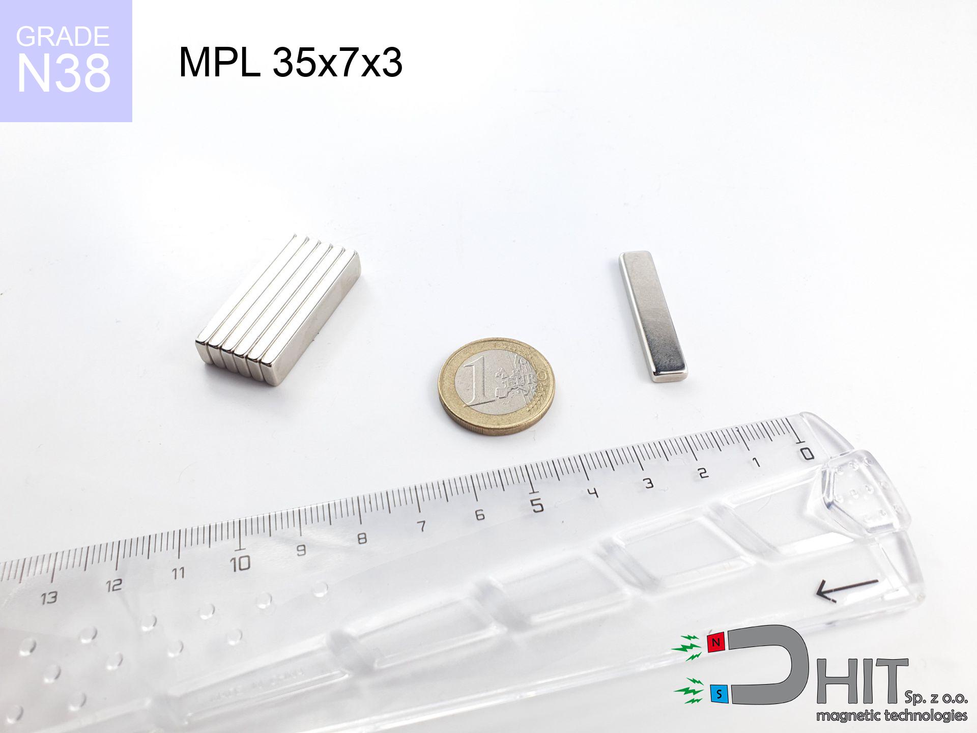
MPL 35x7x3 / N38 - lamellar magnet
lamellar magnet
Catalog no 020145
GTIN/EAN: 5906301811510
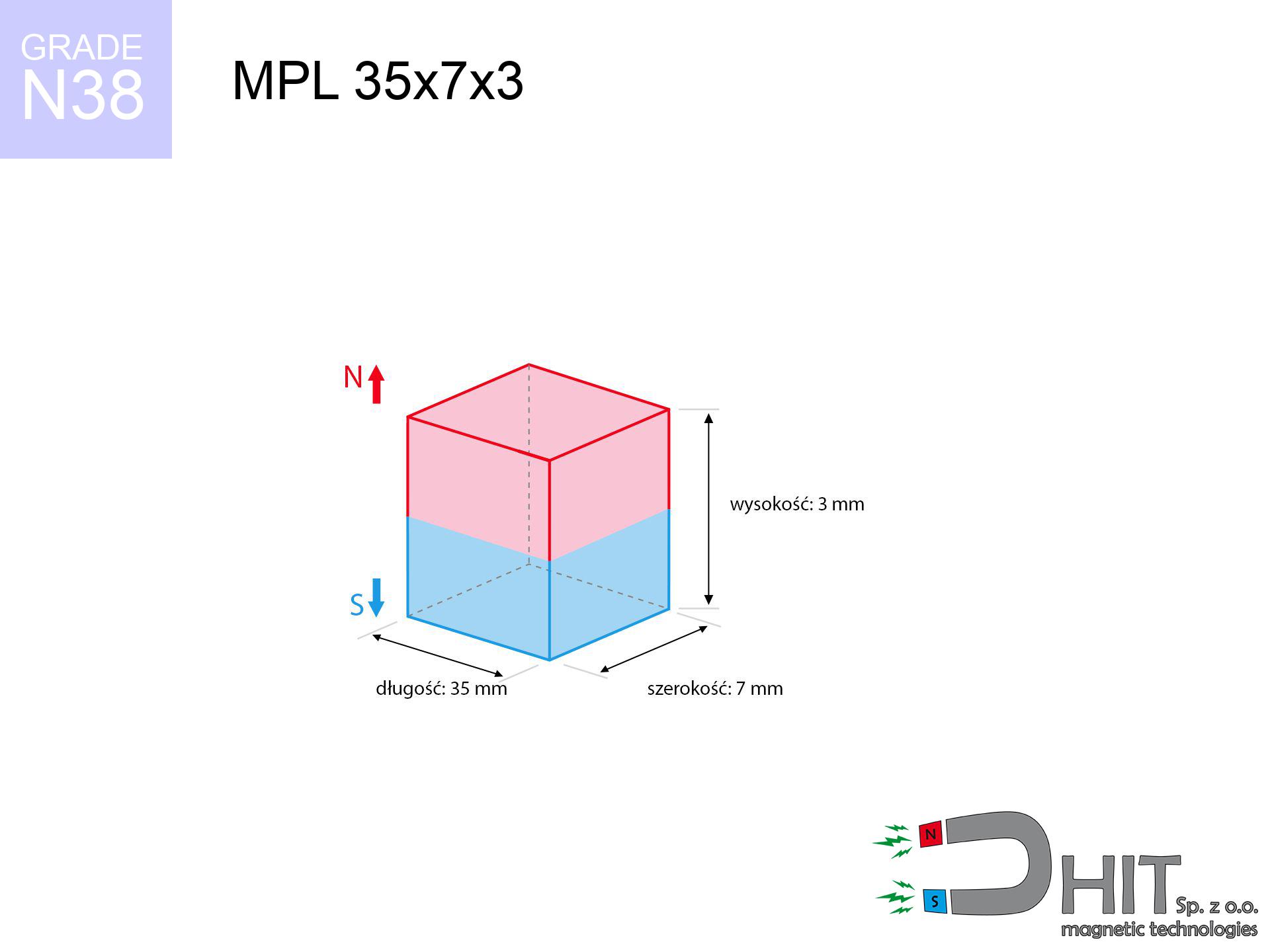
length
35 mm [±0,1 mm]
Width
7 mm [±0,1 mm]
Height
3 mm [±0,1 mm]
Weight
5.51 g
Magnetization Direction
↑ axial
Load capacity
6.21 kg / 60.89 N
Magnetic Induction
285.96 mT / 2860 Gs
Coating
[NiCuNi] Nickel
2.99 ZŁ with VAT / pcs + price for transport
2.43 ZŁ net + 23% VAT / pcs
bulk discounts:
Need more?
Pick up the phone and ask
+48 22 499 98 98
alternatively contact us using
contact form
the contact form page.
Specifications along with shape of neodymium magnets can be calculated using our
our magnetic calculator.
Same-day shipping for orders placed before 14:00.
Product card - MPL 35x7x3 / N38 - lamellar magnet
Specification / characteristics - MPL 35x7x3 / N38 - lamellar magnet
| properties | values |
|---|---|
| Cat. no. | 020145 |
| GTIN/EAN | 5906301811510 |
| Production/Distribution | Dhit sp. z o.o. |
| Country of origin | Poland / China / Germany |
| Customs code | 85059029 |
| length | 35 mm [±0,1 mm] |
| Width | 7 mm [±0,1 mm] |
| Height | 3 mm [±0,1 mm] |
| Weight | 5.51 g |
| Magnetization Direction | ↑ axial |
| Load capacity ~ ? | 6.21 kg / 60.89 N |
| Magnetic Induction ~ ? | 285.96 mT / 2860 Gs |
| Coating | [NiCuNi] Nickel |
| Manufacturing Tolerance | ±0.1 mm |
Magnetic properties of material N38
| properties | values | units |
|---|---|---|
| remenance Br [min. - max.] ? | 12.2-12.6 | kGs |
| remenance Br [min. - max.] ? | 1220-1260 | mT |
| coercivity bHc ? | 10.8-11.5 | kOe |
| coercivity bHc ? | 860-915 | kA/m |
| actual internal force iHc | ≥ 12 | kOe |
| actual internal force iHc | ≥ 955 | kA/m |
| energy density [min. - max.] ? | 36-38 | BH max MGOe |
| energy density [min. - max.] ? | 287-303 | BH max KJ/m |
| max. temperature ? | ≤ 80 | °C |
Physical properties of sintered neodymium magnets Nd2Fe14B at 20°C
| properties | values | units |
|---|---|---|
| Vickers hardness | ≥550 | Hv |
| Density | ≥7.4 | g/cm3 |
| Curie Temperature TC | 312 - 380 | °C |
| Curie Temperature TF | 593 - 716 | °F |
| Specific resistance | 150 | μΩ⋅cm |
| Bending strength | 250 | MPa |
| Compressive strength | 1000~1100 | MPa |
| Thermal expansion parallel (∥) to orientation (M) | (3-4) x 10-6 | °C-1 |
| Thermal expansion perpendicular (⊥) to orientation (M) | -(1-3) x 10-6 | °C-1 |
| Young's modulus | 1.7 x 10⁴ | kg/mm² |
Physical simulation of the product - report
These data are the outcome of a physical simulation. Results rely on algorithms for the material Nd2Fe14B. Operational performance might slightly differ. Treat these calculations as a preliminary roadmap for designers.
Table 1: Static force (force vs distance) - interaction chart
MPL 35x7x3 / N38
| Distance (mm) | Induction (Gauss) / mT | Pull Force (kg/lbs/g/N) | Risk Status |
|---|---|---|---|
| 0 mm |
2858 Gs
285.8 mT
|
6.21 kg / 13.69 lbs
6210.0 g / 60.9 N
|
medium risk |
| 1 mm |
2328 Gs
232.8 mT
|
4.12 kg / 9.09 lbs
4121.1 g / 40.4 N
|
medium risk |
| 2 mm |
1801 Gs
180.1 mT
|
2.47 kg / 5.44 lbs
2467.6 g / 24.2 N
|
medium risk |
| 3 mm |
1376 Gs
137.6 mT
|
1.44 kg / 3.18 lbs
1440.7 g / 14.1 N
|
weak grip |
| 5 mm |
832 Gs
83.2 mT
|
0.53 kg / 1.16 lbs
526.9 g / 5.2 N
|
weak grip |
| 10 mm |
318 Gs
31.8 mT
|
0.08 kg / 0.17 lbs
77.1 g / 0.8 N
|
weak grip |
| 15 mm |
158 Gs
15.8 mT
|
0.02 kg / 0.04 lbs
18.9 g / 0.2 N
|
weak grip |
| 20 mm |
89 Gs
8.9 mT
|
0.01 kg / 0.01 lbs
6.0 g / 0.1 N
|
weak grip |
| 30 mm |
35 Gs
3.5 mT
|
0.00 kg / 0.00 lbs
1.0 g / 0.0 N
|
weak grip |
| 50 mm |
10 Gs
1.0 mT
|
0.00 kg / 0.00 lbs
0.1 g / 0.0 N
|
weak grip |
Table 2: Slippage capacity (vertical surface)
MPL 35x7x3 / N38
| Distance (mm) | Friction coefficient | Pull Force (kg/lbs/g/N) |
|---|---|---|
| 0 mm | Stal (~0.2) |
1.24 kg / 2.74 lbs
1242.0 g / 12.2 N
|
| 1 mm | Stal (~0.2) |
0.82 kg / 1.82 lbs
824.0 g / 8.1 N
|
| 2 mm | Stal (~0.2) |
0.49 kg / 1.09 lbs
494.0 g / 4.8 N
|
| 3 mm | Stal (~0.2) |
0.29 kg / 0.63 lbs
288.0 g / 2.8 N
|
| 5 mm | Stal (~0.2) |
0.11 kg / 0.23 lbs
106.0 g / 1.0 N
|
| 10 mm | Stal (~0.2) |
0.02 kg / 0.04 lbs
16.0 g / 0.2 N
|
| 15 mm | Stal (~0.2) |
0.00 kg / 0.01 lbs
4.0 g / 0.0 N
|
| 20 mm | Stal (~0.2) |
0.00 kg / 0.00 lbs
2.0 g / 0.0 N
|
| 30 mm | Stal (~0.2) |
0.00 kg / 0.00 lbs
0.0 g / 0.0 N
|
| 50 mm | Stal (~0.2) |
0.00 kg / 0.00 lbs
0.0 g / 0.0 N
|
Table 3: Vertical assembly (shearing) - vertical pull
MPL 35x7x3 / N38
| Surface type | Friction coefficient / % Mocy | Max load (kg/lbs/g/N) |
|---|---|---|
| Raw steel |
µ = 0.3
30% Nominalnej Siły
|
1.86 kg / 4.11 lbs
1863.0 g / 18.3 N
|
| Painted steel (standard) |
µ = 0.2
20% Nominalnej Siły
|
1.24 kg / 2.74 lbs
1242.0 g / 12.2 N
|
| Oily/slippery steel |
µ = 0.1
10% Nominalnej Siły
|
0.62 kg / 1.37 lbs
621.0 g / 6.1 N
|
| Magnet with anti-slip rubber |
µ = 0.5
50% Nominalnej Siły
|
3.11 kg / 6.85 lbs
3105.0 g / 30.5 N
|
Table 4: Steel thickness (substrate influence) - sheet metal selection
MPL 35x7x3 / N38
| Steel thickness (mm) | % power | Real pull force (kg/lbs/g/N) |
|---|---|---|
| 0.5 mm |
|
0.62 kg / 1.37 lbs
621.0 g / 6.1 N
|
| 1 mm |
|
1.55 kg / 3.42 lbs
1552.5 g / 15.2 N
|
| 2 mm |
|
3.11 kg / 6.85 lbs
3105.0 g / 30.5 N
|
| 3 mm |
|
4.66 kg / 10.27 lbs
4657.5 g / 45.7 N
|
| 5 mm |
|
6.21 kg / 13.69 lbs
6210.0 g / 60.9 N
|
| 10 mm |
|
6.21 kg / 13.69 lbs
6210.0 g / 60.9 N
|
| 11 mm |
|
6.21 kg / 13.69 lbs
6210.0 g / 60.9 N
|
| 12 mm |
|
6.21 kg / 13.69 lbs
6210.0 g / 60.9 N
|
Table 5: Thermal resistance (material behavior) - resistance threshold
MPL 35x7x3 / N38
| Ambient temp. (°C) | Power loss | Remaining pull (kg/lbs/g/N) | Status |
|---|---|---|---|
| 20 °C | 0.0% |
6.21 kg / 13.69 lbs
6210.0 g / 60.9 N
|
OK |
| 40 °C | -2.2% |
6.07 kg / 13.39 lbs
6073.4 g / 59.6 N
|
OK |
| 60 °C | -4.4% |
5.94 kg / 13.09 lbs
5936.8 g / 58.2 N
|
|
| 80 °C | -6.6% |
5.80 kg / 12.79 lbs
5800.1 g / 56.9 N
|
|
| 100 °C | -28.8% |
4.42 kg / 9.75 lbs
4421.5 g / 43.4 N
|
Table 6: Two magnets (repulsion) - forces in the system
MPL 35x7x3 / N38
| Gap (mm) | Attraction (kg/lbs) (N-S) | Sliding Force (kg/lbs/g/N) | Repulsion (kg/lbs) (N-N) |
|---|---|---|---|
| 0 mm |
12.34 kg / 27.19 lbs
4 231 Gs
|
1.85 kg / 4.08 lbs
1850 g / 18.2 N
|
N/A |
| 1 mm |
10.25 kg / 22.59 lbs
5 209 Gs
|
1.54 kg / 3.39 lbs
1537 g / 15.1 N
|
9.22 kg / 20.33 lbs
~0 Gs
|
| 2 mm |
8.19 kg / 18.05 lbs
4 656 Gs
|
1.23 kg / 2.71 lbs
1228 g / 12.0 N
|
7.37 kg / 16.24 lbs
~0 Gs
|
| 3 mm |
6.38 kg / 14.07 lbs
4 110 Gs
|
0.96 kg / 2.11 lbs
957 g / 9.4 N
|
5.74 kg / 12.66 lbs
~0 Gs
|
| 5 mm |
3.74 kg / 8.25 lbs
3 149 Gs
|
0.56 kg / 1.24 lbs
562 g / 5.5 N
|
3.37 kg / 7.43 lbs
~0 Gs
|
| 10 mm |
1.05 kg / 2.31 lbs
1 665 Gs
|
0.16 kg / 0.35 lbs
157 g / 1.5 N
|
0.94 kg / 2.08 lbs
~0 Gs
|
| 20 mm |
0.15 kg / 0.34 lbs
637 Gs
|
0.02 kg / 0.05 lbs
23 g / 0.2 N
|
0.14 kg / 0.30 lbs
~0 Gs
|
| 50 mm |
0.00 kg / 0.01 lbs
109 Gs
|
0.00 kg / 0.00 lbs
1 g / 0.0 N
|
0.00 kg / 0.00 lbs
~0 Gs
|
| 60 mm |
0.00 kg / 0.00 lbs
71 Gs
|
0.00 kg / 0.00 lbs
0 g / 0.0 N
|
0.00 kg / 0.00 lbs
~0 Gs
|
| 70 mm |
0.00 kg / 0.00 lbs
48 Gs
|
0.00 kg / 0.00 lbs
0 g / 0.0 N
|
0.00 kg / 0.00 lbs
~0 Gs
|
| 80 mm |
0.00 kg / 0.00 lbs
34 Gs
|
0.00 kg / 0.00 lbs
0 g / 0.0 N
|
0.00 kg / 0.00 lbs
~0 Gs
|
| 90 mm |
0.00 kg / 0.00 lbs
25 Gs
|
0.00 kg / 0.00 lbs
0 g / 0.0 N
|
0.00 kg / 0.00 lbs
~0 Gs
|
| 100 mm |
0.00 kg / 0.00 lbs
19 Gs
|
0.00 kg / 0.00 lbs
0 g / 0.0 N
|
0.00 kg / 0.00 lbs
~0 Gs
|
Table 7: Safety (HSE) (implants) - precautionary measures
MPL 35x7x3 / N38
| Object / Device | Limit (Gauss) / mT | Safe distance |
|---|---|---|
| Pacemaker | 5 Gs (0.5 mT) | 6.5 cm |
| Hearing aid | 10 Gs (1.0 mT) | 5.0 cm |
| Timepiece | 20 Gs (2.0 mT) | 4.0 cm |
| Phone / Smartphone | 40 Gs (4.0 mT) | 3.0 cm |
| Remote | 50 Gs (5.0 mT) | 3.0 cm |
| Payment card | 400 Gs (40.0 mT) | 1.0 cm |
| HDD hard drive | 600 Gs (60.0 mT) | 1.0 cm |
Table 8: Collisions (cracking risk) - warning
MPL 35x7x3 / N38
| Start from (mm) | Speed (km/h) | Energy (J) | Predicted outcome |
|---|---|---|---|
| 10 mm |
34.12 km/h
(9.48 m/s)
|
0.25 J | |
| 30 mm |
58.65 km/h
(16.29 m/s)
|
0.73 J | |
| 50 mm |
75.71 km/h
(21.03 m/s)
|
1.22 J | |
| 100 mm |
107.07 km/h
(29.74 m/s)
|
2.44 J |
Table 9: Anti-corrosion coating durability
MPL 35x7x3 / N38
| Technical parameter | Value / Description |
|---|---|
| Coating type | [NiCuNi] Nickel |
| Layer structure | Nickel - Copper - Nickel |
| Layer thickness | 10-20 µm |
| Salt spray test (SST) ? | 24 h |
| Recommended environment | Indoors only (dry) |
Table 10: Electrical data (Pc)
MPL 35x7x3 / N38
| Parameter | Value | SI Unit / Description |
|---|---|---|
| Magnetic Flux | 5 851 Mx | 58.5 µWb |
| Pc Coefficient | 0.25 | Low (Flat) |
Table 11: Underwater work (magnet fishing)
MPL 35x7x3 / N38
| Environment | Effective steel pull | Effect |
|---|---|---|
| Air (land) | 6.21 kg | Standard |
| Water (riverbed) |
7.11 kg
(+0.90 kg buoyancy gain)
|
+14.5% |
1. Shear force
*Warning: On a vertical surface, the magnet holds merely a fraction of its perpendicular strength.
2. Steel thickness impact
*Thin metal sheet (e.g. computer case) drastically limits the holding force.
3. Thermal stability
*For N38 material, the safety limit is 80°C.
4. Demagnetization curve and operating point (B-H)
chart generated for the permeance coefficient Pc (Permeance Coefficient) = 0.25
The chart above illustrates the magnetic characteristics of the material within the second quadrant of the hysteresis loop. The solid red line represents the demagnetization curve (material potential), while the dashed blue line is the load line based on the magnet's geometry. The Pc (Permeance Coefficient), also known as the load line slope, is a dimensionless value that describes the relationship between the magnet's shape and its magnetic stability. The intersection of these two lines (the black dot) is the operating point — it determines the actual magnetic flux density generated by the magnet in this specific configuration. A higher Pc value means the magnet is more 'slender' (tall relative to its area), resulting in a higher operating point and better resistance to irreversible demagnetization caused by external fields or temperature. A value of 0.42 is relatively low (typical for flat magnets), meaning the operating point is closer to the 'knee' of the curve — caution is advised when operating at temperatures near the maximum limit to avoid strength loss.
Material specification
| iron (Fe) | 64% – 68% |
| neodymium (Nd) | 29% – 32% |
| boron (B) | 1.1% – 1.2% |
| dysprosium (Dy) | 0.5% – 2.0% |
| coating (Ni-Cu-Ni) | < 0.05% |
Environmental data
| recyclability (EoL) | 100% |
| recycled raw materials | ~10% (pre-cons) |
| carbon footprint | low / zredukowany |
| waste code (EWC) | 16 02 16 |
Other offers

![SM 25x125 [2xM8] / N42 - magnetic separator](https://cdn3.dhit.pl/graphics/products/sm-25x125-2xm8-duj.jpg "SM 25x125 [2xM8] / N42 - magnetic separator")


Advantages as well as disadvantages of neodymium magnets.
Strengths
- They do not lose power, even after approximately ten years – the drop in power is only ~1% (theoretically),
- Neodymium magnets are extremely resistant to demagnetization caused by external field sources,
- A magnet with a metallic gold surface is more attractive,
- They are known for high magnetic induction at the operating surface, making them more effective,
- Through (appropriate) combination of ingredients, they can achieve high thermal resistance, allowing for operation at temperatures approaching 230°C and above...
- Possibility of individual shaping as well as optimizing to individual needs,
- Universal use in electronics industry – they are commonly used in magnetic memories, brushless drives, medical devices, and modern systems.
- Thanks to efficiency per cm³, small magnets offer high operating force, in miniature format,
Disadvantages
- To avoid cracks under impact, we recommend using special steel housings. Such a solution protects the magnet and simultaneously improves its durability.
- We warn that neodymium magnets can reduce their strength at high temperatures. To prevent this, we advise our specialized [AH] magnets, which work effectively even at 230°C.
- Magnets exposed to a humid environment can rust. Therefore when using outdoors, we advise using water-impermeable magnets made of rubber, plastic or other material resistant to moisture
- We suggest casing - magnetic mechanism, due to difficulties in realizing nuts inside the magnet and complex forms.
- Potential hazard resulting from small fragments of magnets can be dangerous, when accidentally swallowed, which is particularly important in the aspect of protecting the youngest. It is also worth noting that small elements of these magnets can be problematic in diagnostics medical when they are in the body.
- High unit price – neodymium magnets have a higher price than other types of magnets (e.g. ferrite), which hinders application in large quantities
Pull force analysis
Detachment force of the magnet in optimal conditions – what affects it?
- using a base made of low-carbon steel, acting as a ideal flux conductor
- whose thickness equals approx. 10 mm
- with a plane cleaned and smooth
- without any insulating layer between the magnet and steel
- during detachment in a direction vertical to the mounting surface
- in temp. approx. 20°C
Practical aspects of lifting capacity – factors
- Distance (between the magnet and the plate), because even a tiny clearance (e.g. 0.5 mm) leads to a reduction in lifting capacity by up to 50% (this also applies to varnish, rust or dirt).
- Load vector – maximum parameter is reached only during perpendicular pulling. The force required to slide of the magnet along the plate is typically many times smaller (approx. 1/5 of the lifting capacity).
- Base massiveness – insufficiently thick plate causes magnetic saturation, causing part of the flux to be wasted into the air.
- Steel grade – the best choice is high-permeability steel. Cast iron may have worse magnetic properties.
- Surface quality – the smoother and more polished the plate, the larger the contact zone and higher the lifting capacity. Roughness creates an air distance.
- Temperature influence – hot environment reduces magnetic field. Too high temperature can permanently damage the magnet.
Holding force was tested on a smooth steel plate of 20 mm thickness, when a perpendicular force was applied, whereas under parallel forces the lifting capacity is smaller. Additionally, even a minimal clearance between the magnet’s surface and the plate lowers the holding force.
Warnings
Health Danger
Patients with a heart stimulator should maintain an safe separation from magnets. The magnetic field can interfere with the operation of the implant.
Allergic reactions
Nickel alert: The Ni-Cu-Ni coating consists of nickel. If an allergic reaction appears, cease handling magnets and wear gloves.
Maximum temperature
Do not overheat. NdFeB magnets are sensitive to heat. If you require operation above 80°C, look for HT versions (H, SH, UH).
Pinching danger
Danger of trauma: The attraction force is so great that it can cause hematomas, crushing, and broken bones. Use thick gloves.
Phone sensors
A powerful magnetic field disrupts the operation of magnetometers in smartphones and GPS navigation. Do not bring magnets near a smartphone to avoid damaging the sensors.
Protective goggles
Beware of splinters. Magnets can explode upon violent connection, ejecting sharp fragments into the air. Wear goggles.
Safe distance
Data protection: Neodymium magnets can damage payment cards and delicate electronics (heart implants, hearing aids, mechanical watches).
Powerful field
Before starting, read the rules. Uncontrolled attraction can break the magnet or hurt your hand. Think ahead.
Do not drill into magnets
Powder produced during grinding of magnets is combustible. Avoid drilling into magnets without proper cooling and knowledge.
Do not give to children
Product intended for adults. Small elements pose a choking risk, causing severe trauma. Store away from kids and pets.
Tabela kosztu i czasu dostawy
Płatność przed wysyłką:

GLS kurier
Przesyłka będzie u Ciebie za 2-3 dni
14.99 ZŁ

InPost Paczkomaty 24/7
Przesyłka będzie u Ciebie za 1-2 dni
12.30 ZŁ
Płatność przy odbiorze (pobranie):
GLS kurier
Przesyłka będzie u Ciebie za 1-2 dni
23.00 ZŁ
Rate the product
Your rating