
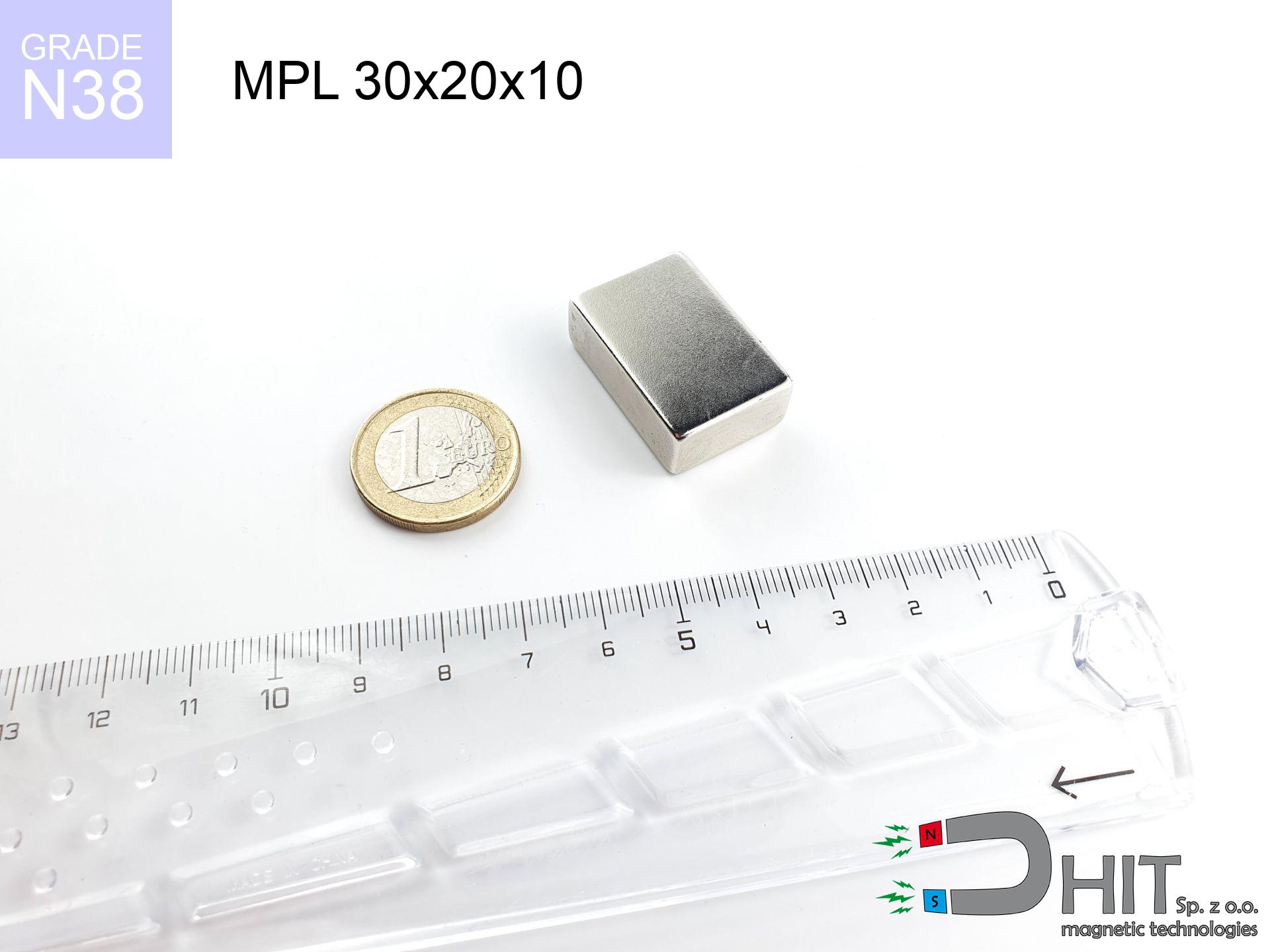
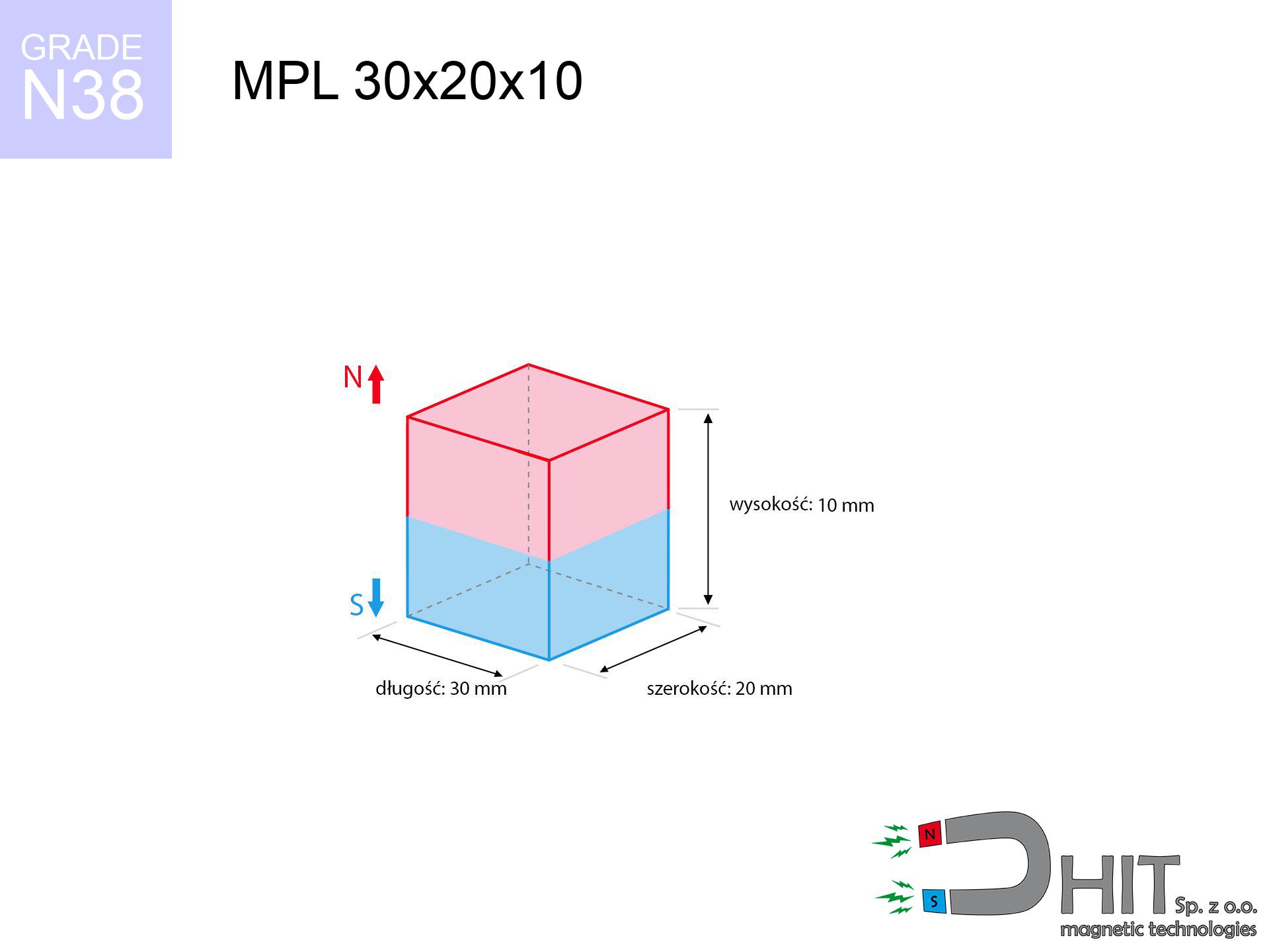
MPL 30x20x10 / N38 - lamellar magnet
lamellar magnet
Catalog no 020141
GTIN/EAN: 5906301811473
length
30 mm [±0,1 mm]
Width
20 mm [±0,1 mm]
Height
10 mm [±0,1 mm]
Weight
45 g
Magnetization Direction
↑ axial
Load capacity
19.53 kg / 191.55 N
Magnetic Induction
371.57 mT / 3716 Gs
Coating
[NiCuNi] Nickel
16.11 ZŁ with VAT / pcs + price for transport
13.10 ZŁ net + 23% VAT / pcs
bulk discounts:
Need more?Engineering report for this magnet
Full PDF analysis: pull and shear force, effect of distance, temperature and plate thickness, safety distances and the demagnetization curve.
Call us now
+48 22 499 98 98
otherwise get in touch via
our online form
our website.
Strength as well as shape of neodymium magnets can be reviewed on our
our magnetic calculator.
Orders placed before 14:00 will be shipped the same business day.
Technical - MPL 30x20x10 / N38 - lamellar magnet
Specification / characteristics - MPL 30x20x10 / N38 - lamellar magnet
| properties | values |
|---|---|
| Cat. no. | 020141 |
| GTIN/EAN | 5906301811473 |
| Production/Distribution | Dhit sp. z o.o. |
| Country of origin | Poland / China / Germany |
| Customs code | 85059029 |
| length | 30 mm [±0,1 mm] |
| Width | 20 mm [±0,1 mm] |
| Height | 10 mm [±0,1 mm] |
| Weight | 45 g |
| Magnetization Direction | ↑ axial |
| Load capacity ~ ? | 19.53 kg / 191.55 N |
| Magnetic Induction ~ ? | 371.57 mT / 3716 Gs |
| Coating | [NiCuNi] Nickel |
| Manufacturing Tolerance | ±0.1 mm |
Magnetic properties of material N38
| properties | values | units |
|---|---|---|
| remenance Br [min. - max.] ? | 12.2-12.6 | kGs |
| remenance Br [min. - max.] ? | 1220-1260 | mT |
| coercivity bHc ? | 10.8-11.5 | kOe |
| coercivity bHc ? | 860-915 | kA/m |
| actual internal force iHc | ≥ 12 | kOe |
| actual internal force iHc | ≥ 955 | kA/m |
| energy density [min. - max.] ? | 36-38 | BH max MGOe |
| energy density [min. - max.] ? | 287-303 | BH max KJ/m |
| max. temperature ? | ≤ 80 | °C |
Physical properties of sintered neodymium magnets Nd2Fe14B at 20°C
| properties | values | units |
|---|---|---|
| Vickers hardness | ≥550 | Hv |
| Density | ≥7.4 | g/cm3 |
| Curie Temperature TC | 312 - 380 | °C |
| Curie Temperature TF | 593 - 716 | °F |
| Specific resistance | 150 | μΩ⋅cm |
| Bending strength | 250 | MPa |
| Compressive strength | 1000~1100 | MPa |
| Thermal expansion parallel (∥) to orientation (M) | (3-4) x 10-6 | °C-1 |
| Thermal expansion perpendicular (⊥) to orientation (M) | -(1-3) x 10-6 | °C-1 |
| Young's modulus | 1.7 x 10⁴ | kg/mm² |
Engineering modeling of the product - data
Presented information constitute the outcome of a engineering calculation. Values are based on algorithms for the material Nd2Fe14B. Actual conditions might slightly deviate from the simulation results. Please consider these calculations as a preliminary roadmap for designers.
Table 1: Static force (force vs gap) - characteristics
MPL 30x20x10 / N38
| Distance (mm) | Induction (Gauss) / mT | Pull Force (kg/lbs/g/N) | Risk Status |
|---|---|---|---|
| 0 mm |
3715 Gs
371.5 mT
|
19.53 kg / 43.06 pounds
19530.0 g / 191.6 N
|
dangerous! |
| 1 mm |
3464 Gs
346.4 mT
|
16.98 kg / 37.44 pounds
16983.1 g / 166.6 N
|
dangerous! |
| 2 mm |
3197 Gs
319.7 mT
|
14.47 kg / 31.89 pounds
14466.6 g / 141.9 N
|
dangerous! |
| 3 mm |
2927 Gs
292.7 mT
|
12.12 kg / 26.73 pounds
12123.3 g / 118.9 N
|
dangerous! |
| 5 mm |
2408 Gs
240.8 mT
|
8.21 kg / 18.10 pounds
8207.8 g / 80.5 N
|
strong |
| 10 mm |
1411 Gs
141.1 mT
|
2.82 kg / 6.21 pounds
2815.6 g / 27.6 N
|
strong |
| 15 mm |
832 Gs
83.2 mT
|
0.98 kg / 2.16 pounds
979.7 g / 9.6 N
|
safe |
| 20 mm |
512 Gs
51.2 mT
|
0.37 kg / 0.82 pounds
371.2 g / 3.6 N
|
safe |
| 30 mm |
224 Gs
22.4 mT
|
0.07 kg / 0.16 pounds
70.7 g / 0.7 N
|
safe |
| 50 mm |
65 Gs
6.5 mT
|
0.01 kg / 0.01 pounds
6.0 g / 0.1 N
|
safe |
Table 2: Sliding load (vertical surface)
MPL 30x20x10 / N38
| Distance (mm) | Friction coefficient | Pull Force (kg/lbs/g/N) |
|---|---|---|
| 0 mm | Stal (~0.2) |
3.91 kg / 8.61 pounds
3906.0 g / 38.3 N
|
| 1 mm | Stal (~0.2) |
3.40 kg / 7.49 pounds
3396.0 g / 33.3 N
|
| 2 mm | Stal (~0.2) |
2.89 kg / 6.38 pounds
2894.0 g / 28.4 N
|
| 3 mm | Stal (~0.2) |
2.42 kg / 5.34 pounds
2424.0 g / 23.8 N
|
| 5 mm | Stal (~0.2) |
1.64 kg / 3.62 pounds
1642.0 g / 16.1 N
|
| 10 mm | Stal (~0.2) |
0.56 kg / 1.24 pounds
564.0 g / 5.5 N
|
| 15 mm | Stal (~0.2) |
0.20 kg / 0.43 pounds
196.0 g / 1.9 N
|
| 20 mm | Stal (~0.2) |
0.07 kg / 0.16 pounds
74.0 g / 0.7 N
|
| 30 mm | Stal (~0.2) |
0.01 kg / 0.03 pounds
14.0 g / 0.1 N
|
| 50 mm | Stal (~0.2) |
0.00 kg / 0.00 pounds
2.0 g / 0.0 N
|
Table 3: Wall mounting (shearing) - behavior on slippery surfaces
MPL 30x20x10 / N38
| Surface type | Friction coefficient / % Mocy | Max load (kg/lbs/g/N) |
|---|---|---|
| Raw steel |
µ = 0.3
30% Nominalnej Siły
|
5.86 kg / 12.92 pounds
5859.0 g / 57.5 N
|
| Painted steel (standard) |
µ = 0.2
20% Nominalnej Siły
|
3.91 kg / 8.61 pounds
3906.0 g / 38.3 N
|
| Oily/slippery steel |
µ = 0.1
10% Nominalnej Siły
|
1.95 kg / 4.31 pounds
1953.0 g / 19.2 N
|
| Magnet with anti-slip rubber |
µ = 0.5
50% Nominalnej Siły
|
9.77 kg / 21.53 pounds
9765.0 g / 95.8 N
|
Table 4: Steel thickness (saturation) - sheet metal selection
MPL 30x20x10 / N38
| Steel thickness (mm) | % power | Real pull force (kg/lbs/g/N) |
|---|---|---|
| 0.5 mm |
|
0.98 kg / 2.15 pounds
976.5 g / 9.6 N
|
| 1 mm |
|
2.44 kg / 5.38 pounds
2441.3 g / 23.9 N
|
| 2 mm |
|
4.88 kg / 10.76 pounds
4882.5 g / 47.9 N
|
| 3 mm |
|
7.32 kg / 16.15 pounds
7323.8 g / 71.8 N
|
| 5 mm |
|
12.21 kg / 26.91 pounds
12206.3 g / 119.7 N
|
| 10 mm |
|
19.53 kg / 43.06 pounds
19530.0 g / 191.6 N
|
| 11 mm |
|
19.53 kg / 43.06 pounds
19530.0 g / 191.6 N
|
| 12 mm |
|
19.53 kg / 43.06 pounds
19530.0 g / 191.6 N
|
Table 5: Thermal resistance (material behavior) - resistance threshold
MPL 30x20x10 / N38
| Ambient temp. (°C) | Power loss | Remaining pull (kg/lbs/g/N) | Status |
|---|---|---|---|
| 20 °C | 0.0% |
19.53 kg / 43.06 pounds
19530.0 g / 191.6 N
|
OK |
| 40 °C | -2.2% |
19.10 kg / 42.11 pounds
19100.3 g / 187.4 N
|
OK |
| 60 °C | -4.4% |
18.67 kg / 41.16 pounds
18670.7 g / 183.2 N
|
|
| 80 °C | -6.6% |
18.24 kg / 40.21 pounds
18241.0 g / 178.9 N
|
|
| 100 °C | -28.8% |
13.91 kg / 30.66 pounds
13905.4 g / 136.4 N
|
Table 6: Magnet-Magnet interaction (repulsion) - field collision
MPL 30x20x10 / N38
| Gap (mm) | Attraction (kg/lbs) (N-S) | Shear Strength (kg/lbs/g/N) | Repulsion (kg/lbs) (N-N) |
|---|---|---|---|
| 0 mm |
51.05 kg / 112.54 pounds
5 124 Gs
|
7.66 kg / 16.88 pounds
7657 g / 75.1 N
|
N/A |
| 1 mm |
47.76 kg / 105.28 pounds
7 186 Gs
|
7.16 kg / 15.79 pounds
7163 g / 70.3 N
|
42.98 kg / 94.76 pounds
~0 Gs
|
| 2 mm |
44.39 kg / 97.86 pounds
6 928 Gs
|
6.66 kg / 14.68 pounds
6658 g / 65.3 N
|
39.95 kg / 88.08 pounds
~0 Gs
|
| 3 mm |
41.06 kg / 90.52 pounds
6 663 Gs
|
6.16 kg / 13.58 pounds
6159 g / 60.4 N
|
36.95 kg / 81.47 pounds
~0 Gs
|
| 5 mm |
34.68 kg / 76.45 pounds
6 124 Gs
|
5.20 kg / 11.47 pounds
5202 g / 51.0 N
|
31.21 kg / 68.81 pounds
~0 Gs
|
| 10 mm |
21.45 kg / 47.30 pounds
4 817 Gs
|
3.22 kg / 7.09 pounds
3218 g / 31.6 N
|
19.31 kg / 42.57 pounds
~0 Gs
|
| 20 mm |
7.36 kg / 16.22 pounds
2 821 Gs
|
1.10 kg / 2.43 pounds
1104 g / 10.8 N
|
6.62 kg / 14.60 pounds
~0 Gs
|
| 50 mm |
0.40 kg / 0.89 pounds
662 Gs
|
0.06 kg / 0.13 pounds
61 g / 0.6 N
|
0.36 kg / 0.80 pounds
~0 Gs
|
| 60 mm |
0.18 kg / 0.41 pounds
447 Gs
|
0.03 kg / 0.06 pounds
28 g / 0.3 N
|
0.17 kg / 0.37 pounds
~0 Gs
|
| 70 mm |
0.09 kg / 0.20 pounds
314 Gs
|
0.01 kg / 0.03 pounds
14 g / 0.1 N
|
0.08 kg / 0.18 pounds
~0 Gs
|
| 80 mm |
0.05 kg / 0.11 pounds
228 Gs
|
0.01 kg / 0.02 pounds
7 g / 0.1 N
|
0.04 kg / 0.10 pounds
~0 Gs
|
| 90 mm |
0.03 kg / 0.06 pounds
170 Gs
|
0.00 kg / 0.01 pounds
4 g / 0.0 N
|
0.02 kg / 0.05 pounds
~0 Gs
|
| 100 mm |
0.02 kg / 0.03 pounds
130 Gs
|
0.00 kg / 0.01 pounds
2 g / 0.0 N
|
0.01 kg / 0.03 pounds
~0 Gs
|
Table 7: Hazards (implants) - warnings
MPL 30x20x10 / N38
| Object / Device | Limit (Gauss) / mT | Safe distance |
|---|---|---|
| Pacemaker | 5 Gs (0.5 mT) | 13.0 cm |
| Hearing aid | 10 Gs (1.0 mT) | 10.0 cm |
| Timepiece | 20 Gs (2.0 mT) | 8.0 cm |
| Phone / Smartphone | 40 Gs (4.0 mT) | 6.5 cm |
| Remote | 50 Gs (5.0 mT) | 6.0 cm |
| Payment card | 400 Gs (40.0 mT) | 2.5 cm |
| HDD hard drive | 600 Gs (60.0 mT) | 2.0 cm |
Table 8: Collisions (kinetic energy) - warning
MPL 30x20x10 / N38
| Start from (mm) | Speed (km/h) | Energy (J) | Predicted outcome |
|---|---|---|---|
| 10 mm |
22.82 km/h
(6.34 m/s)
|
0.90 J | |
| 30 mm |
36.47 km/h
(10.13 m/s)
|
2.31 J | |
| 50 mm |
46.99 km/h
(13.05 m/s)
|
3.83 J | |
| 100 mm |
66.44 km/h
(18.46 m/s)
|
7.66 J |
Table 9: Anti-corrosion coating durability
MPL 30x20x10 / N38
| Technical parameter | Value / Description |
|---|---|
| Coating type | [NiCuNi] Nickel |
| Layer structure | Nickel - Copper - Nickel |
| Layer thickness | 10-20 µm |
| Salt spray test (SST) ? | 24 h |
| Recommended environment | Indoors only (dry) |
Table 10: Construction data (Pc)
MPL 30x20x10 / N38
| Parameter | Value | SI Unit / Description |
|---|---|---|
| Magnetic Flux | 22 801 Mx | 228.0 µWb |
| Pc Coefficient | 0.46 | Low (Flat) |
Table 11: Hydrostatics and buoyancy
MPL 30x20x10 / N38
| Environment | Effective steel pull | Effect |
|---|---|---|
| Air (land) | 19.53 kg | Standard |
| Water (riverbed) |
22.36 kg
(+2.83 kg buoyancy gain)
|
+14.5% |
1. Vertical hold
*Caution: On a vertical surface, the magnet holds just ~20% of its nominal pull.
2. Plate thickness effect
*Thin metal sheet (e.g. 0.5mm PC case) drastically limits the holding force.
3. Temperature resistance
*For N38 grade, the max working temp is 80°C.
4. Demagnetization curve and operating point (B-H)
chart generated for the permeance coefficient Pc (Permeance Coefficient) = 0.46
This simulation demonstrates the magnetic stability of the selected magnet under specific geometric conditions. The solid red line represents the demagnetization curve (material potential), while the dashed blue line is the load line based on the magnet's geometry. The Pc (Permeance Coefficient), also known as the load line slope, is a dimensionless value that describes the relationship between the magnet's shape and its magnetic stability. The intersection of these two lines (the black dot) is the operating point — it determines the actual magnetic flux density generated by the magnet in this specific configuration. A higher Pc value means the magnet is more 'slender' (tall relative to its area), resulting in a higher operating point and better resistance to irreversible demagnetization caused by external fields or temperature. A value of 0.42 is relatively low (typical for flat magnets), meaning the operating point is closer to the 'knee' of the curve — caution is advised when operating at temperatures near the maximum limit to avoid strength loss.
Elemental analysis
| iron (Fe) | 64% – 68% |
| neodymium (Nd) | 29% – 32% |
| boron (B) | 1.1% – 1.2% |
| dysprosium (Dy) | 0.5% – 2.0% |
| coating (Ni-Cu-Ni) | < 0.05% |
Ecology and recycling (GPSR)
| recyclability (EoL) | 100% |
| recycled raw materials | ~10% (pre-cons) |
| carbon footprint | low / zredukowany |
| waste code (EWC) | 16 02 16 |
See also products

![HH 25x7.7 [M5] / N38 - through hole magnetic holder](https://cdn3.dhit.pl/graphics/products/hh-25x7.7-m5-pov.jpg "HH 25x7.7 [M5] / N38 - through hole magnetic holder")

![MPL 40x10x5x2[7/3.5] / N38 - lamellar magnet](https://cdn3.dhit.pl/graphics/products/mpl-40x10x5x27-3.5-miw.jpg "MPL 40x10x5x2[7/3.5] / N38 - lamellar magnet")
Strengths as well as weaknesses of neodymium magnets.
Pros
- They have constant strength, and over nearly 10 years their attraction force decreases symbolically – ~1% (in testing),
- They have excellent resistance to magnetism drop when exposed to opposing magnetic fields,
- By covering with a reflective layer of gold, the element acquires an modern look,
- Magnets are distinguished by huge magnetic induction on the surface,
- Neodymium magnets are characterized by extremely high magnetic induction on the magnet surface and are able to act (depending on the shape) even at a temperature of 230°C or more...
- Due to the potential of free forming and customization to unique solutions, neodymium magnets can be created in a broad palette of shapes and sizes, which expands the range of possible applications,
- Versatile presence in innovative solutions – they are utilized in magnetic memories, motor assemblies, precision medical tools, as well as technologically advanced constructions.
- Compactness – despite small sizes they offer powerful magnetic field, making them ideal for precision applications
Weaknesses
- At strong impacts they can break, therefore we recommend placing them in special holders. A metal housing provides additional protection against damage, as well as increases the magnet's durability.
- We warn that neodymium magnets can lose their strength at high temperatures. To prevent this, we advise our specialized [AH] magnets, which work effectively even at 230°C.
- When exposed to humidity, magnets usually rust. For applications outside, it is recommended to use protective magnets, such as those in rubber or plastics, which secure oxidation as well as corrosion.
- We suggest cover - magnetic holder, due to difficulties in producing nuts inside the magnet and complex shapes.
- Possible danger to health – tiny shards of magnets are risky, if swallowed, which gains importance in the context of child health protection. It is also worth noting that tiny parts of these products can complicate diagnosis medical when they are in the body.
- Due to neodymium price, their price exceeds standard values,
Lifting parameters
Maximum holding power of the magnet – what it depends on?
- with the application of a sheet made of special test steel, guaranteeing maximum field concentration
- whose thickness is min. 10 mm
- with an ideally smooth touching surface
- without any clearance between the magnet and steel
- during pulling in a direction vertical to the mounting surface
- at room temperature
Determinants of practical lifting force of a magnet
- Gap between surfaces – every millimeter of distance (caused e.g. by varnish or unevenness) significantly weakens the magnet efficiency, often by half at just 0.5 mm.
- Force direction – declared lifting capacity refers to detachment vertically. When slipping, the magnet exhibits significantly lower power (often approx. 20-30% of nominal force).
- Metal thickness – thin material does not allow full use of the magnet. Magnetic flux passes through the material instead of generating force.
- Metal type – different alloys reacts the same. Alloy additives weaken the attraction effect.
- Surface structure – the more even the plate, the larger the contact zone and stronger the hold. Roughness creates an air distance.
- Temperature – heating the magnet causes a temporary drop of induction. Check the thermal limit for a given model.
Holding force was measured on a smooth steel plate of 20 mm thickness, when the force acted perpendicularly, however under shearing force the lifting capacity is smaller. Additionally, even a small distance between the magnet’s surface and the plate decreases the holding force.
Safety rules for work with NdFeB magnets
Respect the power
Exercise caution. Neodymium magnets attract from a long distance and snap with massive power, often quicker than you can react.
Cards and drives
Avoid bringing magnets near a wallet, computer, or TV. The magnetism can permanently damage these devices and erase data from cards.
Choking Hazard
Only for adults. Small elements pose a choking risk, leading to intestinal necrosis. Keep out of reach of kids and pets.
Magnet fragility
Despite the nickel coating, neodymium is brittle and not impact-resistant. Avoid impacts, as the magnet may shatter into hazardous fragments.
ICD Warning
For implant holders: Strong magnetic fields affect medical devices. Maintain minimum 30 cm distance or ask another person to work with the magnets.
GPS and phone interference
Note: rare earth magnets generate a field that interferes with precision electronics. Maintain a safe distance from your mobile, tablet, and GPS.
Thermal limits
Regular neodymium magnets (N-type) undergo demagnetization when the temperature surpasses 80°C. The loss of strength is permanent.
Machining danger
Mechanical processing of NdFeB material carries a risk of fire risk. Neodymium dust oxidizes rapidly with oxygen and is hard to extinguish.
Allergy Warning
Nickel alert: The nickel-copper-nickel coating contains nickel. If skin irritation appears, cease working with magnets and use protective gear.
Crushing force
Watch your fingers. Two powerful magnets will join immediately with a force of massive weight, destroying anything in their path. Be careful!
Tabela kosztu i czasu dostawy
Płatność przed wysyłką:

GLS kurier
Przesyłka będzie u Ciebie za 2-3 dni
14.99 ZŁ

InPost Paczkomaty 24/7
Przesyłka będzie u Ciebie za 1-2 dni
12.30 ZŁ
Płatność przy odbiorze (pobranie):
GLS kurier
Przesyłka będzie u Ciebie za 1-2 dni
23.00 ZŁ
Rate the product
Your rating