

MPL 25x12.5x5 / N38 - lamellar magnet
lamellar magnet
Catalog no 020136
GTIN/EAN: 5906301811428
length
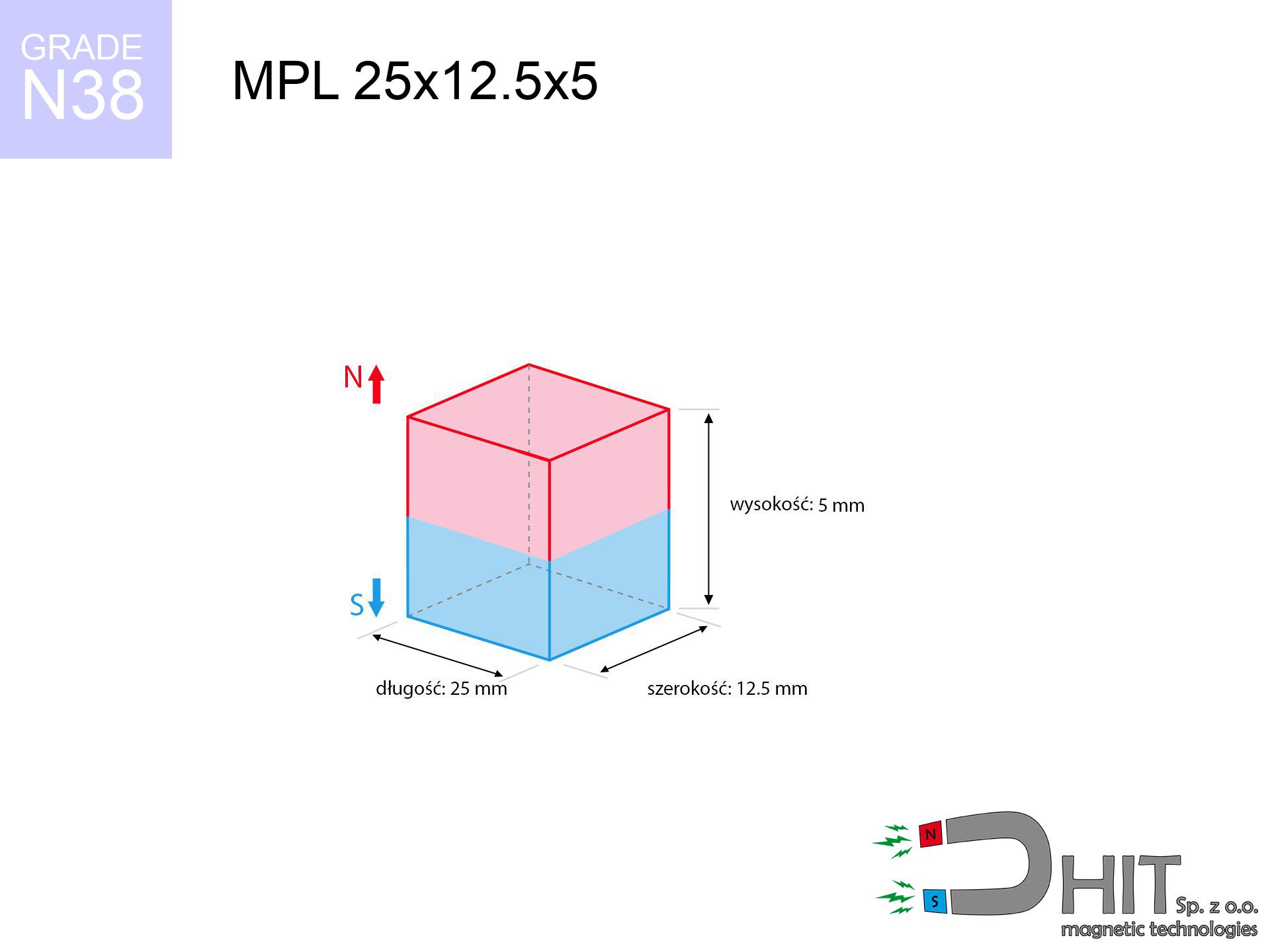
25 mm [±0,1 mm]
Width
12.5 mm [±0,1 mm]
Height
5 mm [±0,1 mm]
Weight
11.72 g
Magnetization Direction
↑ axial
Load capacity
7.72 kg / 75.74 N
Magnetic Induction
299.70 mT / 2997 Gs
Coating
[NiCuNi] Nickel
4.92 ZŁ with VAT / pcs + price for transport
4.00 ZŁ net + 23% VAT / pcs
bulk discounts:
Need more?
Call us now
+48 888 99 98 98
or drop us a message by means of
form
the contact form page.
Strength along with appearance of magnetic components can be reviewed with our
our magnetic calculator.
Order by 14:00 and we’ll ship today!
Technical details - MPL 25x12.5x5 / N38 - lamellar magnet
Specification / characteristics - MPL 25x12.5x5 / N38 - lamellar magnet
| properties | values |
|---|---|
| Cat. no. | 020136 |
| GTIN/EAN | 5906301811428 |
| Production/Distribution | Dhit sp. z o.o. |
| Country of origin | Poland / China / Germany |
| Customs code | 85059029 |
| length | 25 mm [±0,1 mm] |
| Width | 12.5 mm [±0,1 mm] |
| Height | 5 mm [±0,1 mm] |
| Weight | 11.72 g |
| Magnetization Direction | ↑ axial |
| Load capacity ~ ? | 7.72 kg / 75.74 N |
| Magnetic Induction ~ ? | 299.70 mT / 2997 Gs |
| Coating | [NiCuNi] Nickel |
| Manufacturing Tolerance | ±0.1 mm |
Magnetic properties of material N38
| properties | values | units |
|---|---|---|
| remenance Br [min. - max.] ? | 12.2-12.6 | kGs |
| remenance Br [min. - max.] ? | 1220-1260 | mT |
| coercivity bHc ? | 10.8-11.5 | kOe |
| coercivity bHc ? | 860-915 | kA/m |
| actual internal force iHc | ≥ 12 | kOe |
| actual internal force iHc | ≥ 955 | kA/m |
| energy density [min. - max.] ? | 36-38 | BH max MGOe |
| energy density [min. - max.] ? | 287-303 | BH max KJ/m |
| max. temperature ? | ≤ 80 | °C |
Physical properties of sintered neodymium magnets Nd2Fe14B at 20°C
| properties | values | units |
|---|---|---|
| Vickers hardness | ≥550 | Hv |
| Density | ≥7.4 | g/cm3 |
| Curie Temperature TC | 312 - 380 | °C |
| Curie Temperature TF | 593 - 716 | °F |
| Specific resistance | 150 | μΩ⋅cm |
| Bending strength | 250 | MPa |
| Compressive strength | 1000~1100 | MPa |
| Thermal expansion parallel (∥) to orientation (M) | (3-4) x 10-6 | °C-1 |
| Thermal expansion perpendicular (⊥) to orientation (M) | -(1-3) x 10-6 | °C-1 |
| Young's modulus | 1.7 x 10⁴ | kg/mm² |
Technical simulation of the magnet - data
Presented values represent the direct effect of a physical calculation. Values are based on algorithms for the material Nd2Fe14B. Actual performance may deviate from the simulation results. Please consider these calculations as a supplementary guide during assembly planning.
Table 1: Static force (pull vs gap) - interaction chart
MPL 25x12.5x5 / N38
| Distance (mm) | Induction (Gauss) / mT | Pull Force (kg/lbs/g/N) | Risk Status |
|---|---|---|---|
| 0 mm |
2996 Gs
299.6 mT
|
7.72 kg / 17.02 LBS
7720.0 g / 75.7 N
|
strong |
| 1 mm |
2705 Gs
270.5 mT
|
6.29 kg / 13.87 LBS
6292.6 g / 61.7 N
|
strong |
| 2 mm |
2384 Gs
238.4 mT
|
4.89 kg / 10.77 LBS
4886.6 g / 47.9 N
|
strong |
| 3 mm |
2067 Gs
206.7 mT
|
3.67 kg / 8.10 LBS
3674.4 g / 36.0 N
|
strong |
| 5 mm |
1517 Gs
151.7 mT
|
1.98 kg / 4.36 LBS
1979.6 g / 19.4 N
|
safe |
| 10 mm |
702 Gs
70.2 mT
|
0.42 kg / 0.93 LBS
424.1 g / 4.2 N
|
safe |
| 15 mm |
355 Gs
35.5 mT
|
0.11 kg / 0.24 LBS
108.6 g / 1.1 N
|
safe |
| 20 mm |
198 Gs
19.8 mT
|
0.03 kg / 0.07 LBS
33.6 g / 0.3 N
|
safe |
| 30 mm |
76 Gs
7.6 mT
|
0.01 kg / 0.01 LBS
5.0 g / 0.0 N
|
safe |
| 50 mm |
20 Gs
2.0 mT
|
0.00 kg / 0.00 LBS
0.3 g / 0.0 N
|
safe |
Table 2: Slippage capacity (vertical surface)
MPL 25x12.5x5 / N38
| Distance (mm) | Friction coefficient | Pull Force (kg/lbs/g/N) |
|---|---|---|
| 0 mm | Stal (~0.2) |
1.54 kg / 3.40 LBS
1544.0 g / 15.1 N
|
| 1 mm | Stal (~0.2) |
1.26 kg / 2.77 LBS
1258.0 g / 12.3 N
|
| 2 mm | Stal (~0.2) |
0.98 kg / 2.16 LBS
978.0 g / 9.6 N
|
| 3 mm | Stal (~0.2) |
0.73 kg / 1.62 LBS
734.0 g / 7.2 N
|
| 5 mm | Stal (~0.2) |
0.40 kg / 0.87 LBS
396.0 g / 3.9 N
|
| 10 mm | Stal (~0.2) |
0.08 kg / 0.19 LBS
84.0 g / 0.8 N
|
| 15 mm | Stal (~0.2) |
0.02 kg / 0.05 LBS
22.0 g / 0.2 N
|
| 20 mm | Stal (~0.2) |
0.01 kg / 0.01 LBS
6.0 g / 0.1 N
|
| 30 mm | Stal (~0.2) |
0.00 kg / 0.00 LBS
2.0 g / 0.0 N
|
| 50 mm | Stal (~0.2) |
0.00 kg / 0.00 LBS
0.0 g / 0.0 N
|
Table 3: Wall mounting (shearing) - behavior on slippery surfaces
MPL 25x12.5x5 / N38
| Surface type | Friction coefficient / % Mocy | Max load (kg/lbs/g/N) |
|---|---|---|
| Raw steel |
µ = 0.3
30% Nominalnej Siły
|
2.32 kg / 5.11 LBS
2316.0 g / 22.7 N
|
| Painted steel (standard) |
µ = 0.2
20% Nominalnej Siły
|
1.54 kg / 3.40 LBS
1544.0 g / 15.1 N
|
| Oily/slippery steel |
µ = 0.1
10% Nominalnej Siły
|
0.77 kg / 1.70 LBS
772.0 g / 7.6 N
|
| Magnet with anti-slip rubber |
µ = 0.5
50% Nominalnej Siły
|
3.86 kg / 8.51 LBS
3860.0 g / 37.9 N
|
Table 4: Material efficiency (substrate influence) - power losses
MPL 25x12.5x5 / N38
| Steel thickness (mm) | % power | Real pull force (kg/lbs/g/N) |
|---|---|---|
| 0.5 mm |
|
0.77 kg / 1.70 LBS
772.0 g / 7.6 N
|
| 1 mm |
|
1.93 kg / 4.25 LBS
1930.0 g / 18.9 N
|
| 2 mm |
|
3.86 kg / 8.51 LBS
3860.0 g / 37.9 N
|
| 3 mm |
|
5.79 kg / 12.76 LBS
5790.0 g / 56.8 N
|
| 5 mm |
|
7.72 kg / 17.02 LBS
7720.0 g / 75.7 N
|
| 10 mm |
|
7.72 kg / 17.02 LBS
7720.0 g / 75.7 N
|
| 11 mm |
|
7.72 kg / 17.02 LBS
7720.0 g / 75.7 N
|
| 12 mm |
|
7.72 kg / 17.02 LBS
7720.0 g / 75.7 N
|
Table 5: Thermal stability (material behavior) - resistance threshold
MPL 25x12.5x5 / N38
| Ambient temp. (°C) | Power loss | Remaining pull (kg/lbs/g/N) | Status |
|---|---|---|---|
| 20 °C | 0.0% |
7.72 kg / 17.02 LBS
7720.0 g / 75.7 N
|
OK |
| 40 °C | -2.2% |
7.55 kg / 16.65 LBS
7550.2 g / 74.1 N
|
OK |
| 60 °C | -4.4% |
7.38 kg / 16.27 LBS
7380.3 g / 72.4 N
|
|
| 80 °C | -6.6% |
7.21 kg / 15.90 LBS
7210.5 g / 70.7 N
|
|
| 100 °C | -28.8% |
5.50 kg / 12.12 LBS
5496.6 g / 53.9 N
|
Table 6: Magnet-Magnet interaction (repulsion) - forces in the system
MPL 25x12.5x5 / N38
| Gap (mm) | Attraction (kg/lbs) (N-S) | Shear Strength (kg/lbs/g/N) | Repulsion (kg/lbs) (N-N) |
|---|---|---|---|
| 0 mm |
17.29 kg / 38.13 LBS
4 511 Gs
|
2.59 kg / 5.72 LBS
2594 g / 25.4 N
|
N/A |
| 1 mm |
15.73 kg / 34.68 LBS
5 715 Gs
|
2.36 kg / 5.20 LBS
2360 g / 23.2 N
|
14.16 kg / 31.22 LBS
~0 Gs
|
| 2 mm |
14.10 kg / 31.08 LBS
5 410 Gs
|
2.11 kg / 4.66 LBS
2114 g / 20.7 N
|
12.69 kg / 27.97 LBS
~0 Gs
|
| 3 mm |
12.48 kg / 27.52 LBS
5 091 Gs
|
1.87 kg / 4.13 LBS
1872 g / 18.4 N
|
11.23 kg / 24.77 LBS
~0 Gs
|
| 5 mm |
9.52 kg / 20.99 LBS
4 446 Gs
|
1.43 kg / 3.15 LBS
1428 g / 14.0 N
|
8.57 kg / 18.89 LBS
~0 Gs
|
| 10 mm |
4.43 kg / 9.78 LBS
3 034 Gs
|
0.67 kg / 1.47 LBS
665 g / 6.5 N
|
3.99 kg / 8.80 LBS
~0 Gs
|
| 20 mm |
0.95 kg / 2.09 LBS
1 404 Gs
|
0.14 kg / 0.31 LBS
142 g / 1.4 N
|
0.85 kg / 1.88 LBS
~0 Gs
|
| 50 mm |
0.03 kg / 0.06 LBS
238 Gs
|
0.00 kg / 0.01 LBS
4 g / 0.0 N
|
0.02 kg / 0.05 LBS
~0 Gs
|
| 60 mm |
0.01 kg / 0.02 LBS
153 Gs
|
0.00 kg / 0.00 LBS
2 g / 0.0 N
|
0.01 kg / 0.02 LBS
~0 Gs
|
| 70 mm |
0.01 kg / 0.01 LBS
103 Gs
|
0.00 kg / 0.00 LBS
1 g / 0.0 N
|
0.00 kg / 0.00 LBS
~0 Gs
|
| 80 mm |
0.00 kg / 0.01 LBS
73 Gs
|
0.00 kg / 0.00 LBS
0 g / 0.0 N
|
0.00 kg / 0.00 LBS
~0 Gs
|
| 90 mm |
0.00 kg / 0.00 LBS
53 Gs
|
0.00 kg / 0.00 LBS
0 g / 0.0 N
|
0.00 kg / 0.00 LBS
~0 Gs
|
| 100 mm |
0.00 kg / 0.00 LBS
40 Gs
|
0.00 kg / 0.00 LBS
0 g / 0.0 N
|
0.00 kg / 0.00 LBS
~0 Gs
|
Table 7: Protective zones (implants) - precautionary measures
MPL 25x12.5x5 / N38
| Object / Device | Limit (Gauss) / mT | Safe distance |
|---|---|---|
| Pacemaker | 5 Gs (0.5 mT) | 8.5 cm |
| Hearing aid | 10 Gs (1.0 mT) | 6.5 cm |
| Mechanical watch | 20 Gs (2.0 mT) | 5.0 cm |
| Mobile device | 40 Gs (4.0 mT) | 4.0 cm |
| Remote | 50 Gs (5.0 mT) | 4.0 cm |
| Payment card | 400 Gs (40.0 mT) | 1.5 cm |
| HDD hard drive | 600 Gs (60.0 mT) | 1.5 cm |
Table 8: Collisions (cracking risk) - warning
MPL 25x12.5x5 / N38
| Start from (mm) | Speed (km/h) | Energy (J) | Predicted outcome |
|---|---|---|---|
| 10 mm |
26.76 km/h
(7.43 m/s)
|
0.32 J | |
| 30 mm |
44.85 km/h
(12.46 m/s)
|
0.91 J | |
| 50 mm |
57.88 km/h
(16.08 m/s)
|
1.51 J | |
| 100 mm |
81.85 km/h
(22.74 m/s)
|
3.03 J |
Table 9: Corrosion resistance
MPL 25x12.5x5 / N38
| Technical parameter | Value / Description |
|---|---|
| Coating type | [NiCuNi] Nickel |
| Layer structure | Nickel - Copper - Nickel |
| Layer thickness | 10-20 µm |
| Salt spray test (SST) ? | 24 h |
| Recommended environment | Indoors only (dry) |
Table 10: Electrical data (Flux)
MPL 25x12.5x5 / N38
| Parameter | Value | SI Unit / Description |
|---|---|---|
| Magnetic Flux | 9 639 Mx | 96.4 µWb |
| Pc Coefficient | 0.35 | Low (Flat) |
Table 11: Physics of underwater searching
MPL 25x12.5x5 / N38
| Environment | Effective steel pull | Effect |
|---|---|---|
| Air (land) | 7.72 kg | Standard |
| Water (riverbed) |
8.84 kg
(+1.12 kg buoyancy gain)
|
+14.5% |
1. Wall mount (shear)
*Warning: On a vertical wall, the magnet retains just a fraction of its nominal pull.
2. Steel saturation
*Thin metal sheet (e.g. computer case) significantly reduces the holding force.
3. Heat tolerance
*For standard magnets, the safety limit is 80°C.
4. Demagnetization curve and operating point (B-H)
chart generated for the permeance coefficient Pc (Permeance Coefficient) = 0.35
The chart above illustrates the magnetic characteristics of the material within the second quadrant of the hysteresis loop. The solid red line represents the demagnetization curve (material potential), while the dashed blue line is the load line based on the magnet's geometry. The Pc (Permeance Coefficient), also known as the load line slope, is a dimensionless value that describes the relationship between the magnet's shape and its magnetic stability. The intersection of these two lines (the black dot) is the operating point — it determines the actual magnetic flux density generated by the magnet in this specific configuration. A higher Pc value means the magnet is more 'slender' (tall relative to its area), resulting in a higher operating point and better resistance to irreversible demagnetization caused by external fields or temperature. A value of 0.42 is relatively low (typical for flat magnets), meaning the operating point is closer to the 'knee' of the curve — caution is advised when operating at temperatures near the maximum limit to avoid strength loss.
Elemental analysis
| iron (Fe) | 64% – 68% |
| neodymium (Nd) | 29% – 32% |
| boron (B) | 1.1% – 1.2% |
| dysprosium (Dy) | 0.5% – 2.0% |
| coating (Ni-Cu-Ni) | < 0.05% |
Sustainability
| recyclability (EoL) | 100% |
| recycled raw materials | ~10% (pre-cons) |
| carbon footprint | low / zredukowany |
| waste code (EWC) | 16 02 16 |
Other proposals
![UMP 67x28 [M8+M10] GW F120 Lina / N38 - search holder](https://cdn3.dhit.pl/graphics/products/ump-67x28-m8+m10-gw-f-120+-lina-xiw.jpg "UMP 67x28 [M8+M10] GW F120 Lina / N38 - search holder")
![UMP 75x25 [M10x3] GW F200 GOLD / N42 - search holder](https://cdn3.dhit.pl/graphics/products/ump-75x25-m10x3-gw-f200-gold-pag.jpg "UMP 75x25 [M10x3] GW F200 GOLD / N42 - search holder")


Pros as well as cons of Nd2Fe14B magnets.
Benefits
- They do not lose strength, even over nearly 10 years – the drop in strength is only ~1% (theoretically),
- Magnets effectively resist against loss of magnetization caused by ambient magnetic noise,
- The use of an metallic layer of noble metals (nickel, gold, silver) causes the element to be more visually attractive,
- Magnets possess maximum magnetic induction on the active area,
- Made from properly selected components, these magnets show impressive resistance to high heat, enabling them to function (depending on their shape) at temperatures up to 230°C and above...
- Possibility of accurate shaping and modifying to atypical applications,
- Key role in electronics industry – they find application in mass storage devices, drive modules, precision medical tools, also other advanced devices.
- Compactness – despite small sizes they offer powerful magnetic field, making them ideal for precision applications
Weaknesses
- They are prone to damage upon too strong impacts. To avoid cracks, it is worth securing magnets using a steel holder. Such protection not only protects the magnet but also increases its resistance to damage
- Neodymium magnets lose their power under the influence of heating. As soon as 80°C is exceeded, many of them start losing their power. Therefore, we recommend our special magnets marked [AH], which maintain durability even at temperatures up to 230°C
- When exposed to humidity, magnets usually rust. To use them in conditions outside, it is recommended to use protective magnets, such as those in rubber or plastics, which prevent oxidation as well as corrosion.
- Limited possibility of creating threads in the magnet and complex forms - preferred is a housing - magnet mounting.
- Possible danger related to microscopic parts of magnets can be dangerous, in case of ingestion, which gains importance in the aspect of protecting the youngest. It is also worth noting that small components of these magnets are able to be problematic in diagnostics medical when they are in the body.
- Due to expensive raw materials, their price is higher than average,
Pull force analysis
Optimal lifting capacity of a neodymium magnet – what affects it?
- on a block made of mild steel, effectively closing the magnetic field
- possessing a massiveness of minimum 10 mm to ensure full flux closure
- characterized by smoothness
- with direct contact (no coatings)
- under vertical force direction (90-degree angle)
- at room temperature
What influences lifting capacity in practice
- Distance – the presence of foreign body (rust, tape, gap) acts as an insulator, which reduces power steeply (even by 50% at 0.5 mm).
- Load vector – highest force is available only during pulling at a 90° angle. The shear force of the magnet along the surface is typically many times smaller (approx. 1/5 of the lifting capacity).
- Metal thickness – thin material does not allow full use of the magnet. Part of the magnetic field penetrates through instead of generating force.
- Material type – ideal substrate is pure iron steel. Hardened steels may generate lower lifting capacity.
- Base smoothness – the smoother and more polished the surface, the larger the contact zone and stronger the hold. Unevenness creates an air distance.
- Operating temperature – neodymium magnets have a sensitivity to temperature. At higher temperatures they are weaker, and at low temperatures they can be stronger (up to a certain limit).
Lifting capacity testing was conducted on plates with a smooth surface of suitable thickness, under perpendicular forces, in contrast under attempts to slide the magnet the lifting capacity is smaller. Moreover, even a minimal clearance between the magnet’s surface and the plate lowers the lifting capacity.
H&S for magnets
Dust explosion hazard
Combustion risk: Neodymium dust is highly flammable. Do not process magnets without safety gear as this risks ignition.
Power loss in heat
Monitor thermal conditions. Exposing the magnet to high heat will ruin its properties and strength.
Health Danger
Life threat: Strong magnets can deactivate heart devices and defibrillators. Do not approach if you have medical devices.
Safe distance
Equipment safety: Neodymium magnets can ruin payment cards and sensitive devices (pacemakers, hearing aids, mechanical watches).
Fragile material
Protect your eyes. Magnets can fracture upon uncontrolled impact, launching sharp fragments into the air. Wear goggles.
Swallowing risk
Adult use only. Tiny parts pose a choking risk, causing severe trauma. Store out of reach of children and animals.
Phone sensors
An intense magnetic field disrupts the operation of compasses in smartphones and GPS navigation. Do not bring magnets close to a device to avoid damaging the sensors.
Do not underestimate power
Before use, check safety instructions. Sudden snapping can break the magnet or hurt your hand. Be predictive.
Nickel coating and allergies
Medical facts indicate that the nickel plating (standard magnet coating) is a strong allergen. If you have an allergy, prevent touching magnets with bare hands or choose coated magnets.
Crushing risk
Large magnets can crush fingers in a fraction of a second. Do not place your hand betwixt two attracting surfaces.
Tabela kosztu i czasu dostawy
Płatność przed wysyłką:

GLS kurier
Przesyłka będzie u Ciebie za 2-3 dni
14.99 ZŁ

InPost Paczkomaty 24/7
Przesyłka będzie u Ciebie za 1-2 dni
12.30 ZŁ
Płatność przy odbiorze (pobranie):
GLS kurier
Przesyłka będzie u Ciebie za 1-2 dni
23.00 ZŁ
Rate the product
Your rating
e-mail: bok@dhit.pl
tel: +48 888 99 98 98