
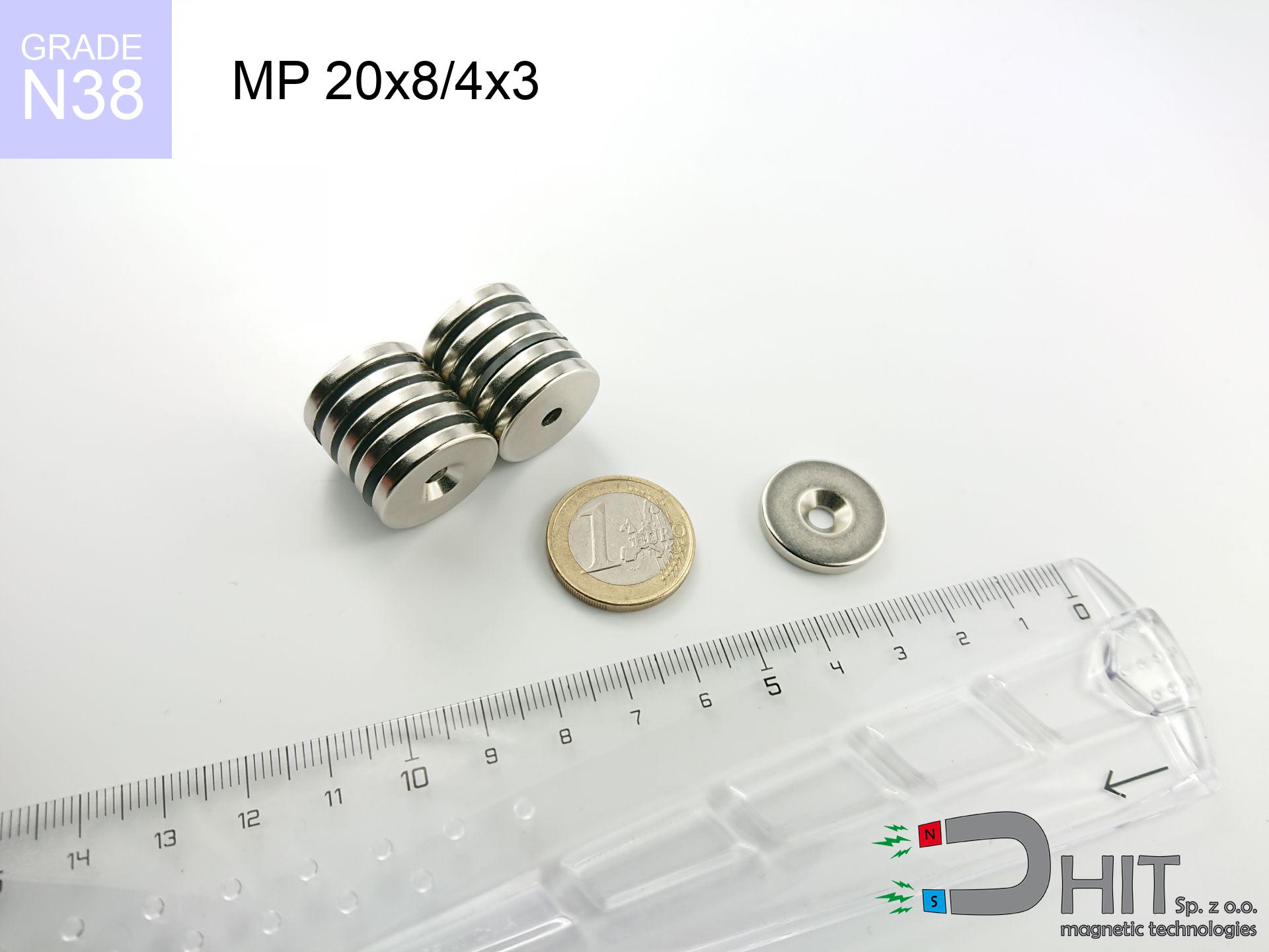
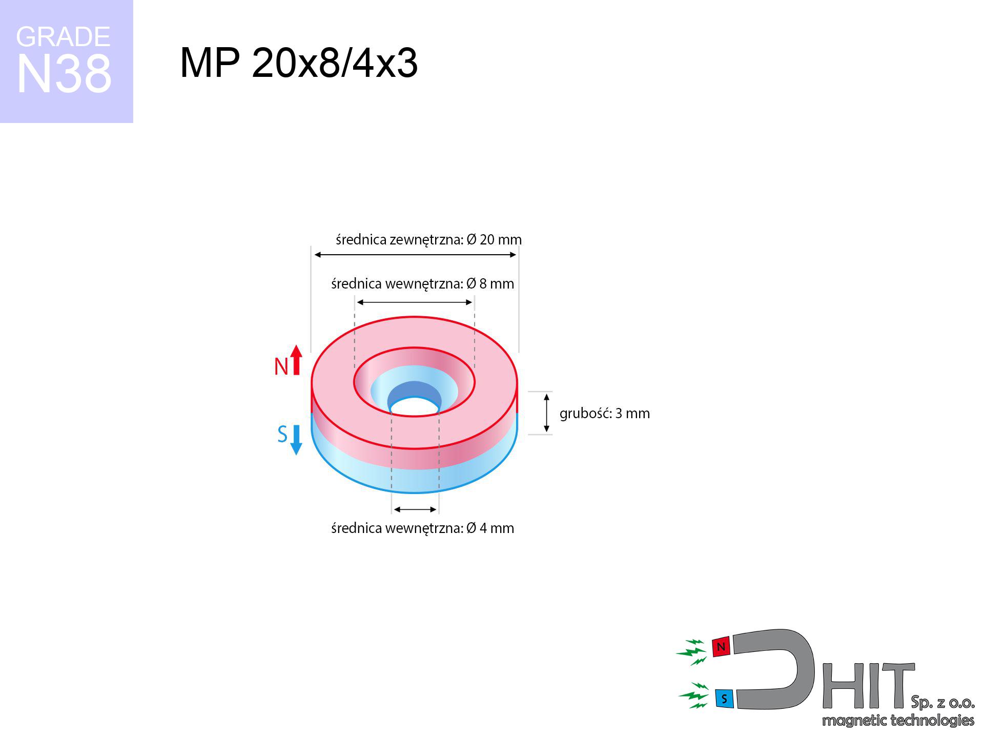
MP 20x8/4x3 / N38 - ring magnet
ring magnet
Catalog no 030187
GTIN/EAN: 5906301812043
Diameter
20 mm [±0,1 mm]
internal diameter Ø
8/4 mm [±0,1 mm]
Height
3 mm [±0,1 mm]
Weight
6.79 g
Magnetization Direction
↑ axial
Load capacity
3.14 kg / 30.79 N
Magnetic Induction
178.11 mT / 1781 Gs
Coating
[NiCuNi] Nickel
3.59 ZŁ with VAT / pcs + price for transport
2.92 ZŁ net + 23% VAT / pcs
bulk discounts:
Need more?
Pick up the phone and ask
+48 22 499 98 98
otherwise drop us a message by means of
our online form
our website.
Parameters as well as structure of magnetic components can be verified on our
modular calculator.
Same-day shipping for orders placed before 14:00.
Technical specification - MP 20x8/4x3 / N38 - ring magnet
Specification / characteristics - MP 20x8/4x3 / N38 - ring magnet
| properties | values |
|---|---|
| Cat. no. | 030187 |
| GTIN/EAN | 5906301812043 |
| Production/Distribution | Dhit sp. z o.o. |
| Country of origin | Poland / China / Germany |
| Customs code | 85059029 |
| Diameter | 20 mm [±0,1 mm] |
| internal diameter Ø | 8/4 mm [±0,1 mm] |
| Height | 3 mm [±0,1 mm] |
| Weight | 6.79 g |
| Magnetization Direction | ↑ axial |
| Load capacity ~ ? | 3.14 kg / 30.79 N |
| Magnetic Induction ~ ? | 178.11 mT / 1781 Gs |
| Coating | [NiCuNi] Nickel |
| Manufacturing Tolerance | ±0.1 mm |
Magnetic properties of material N38
| properties | values | units |
|---|---|---|
| remenance Br [min. - max.] ? | 12.2-12.6 | kGs |
| remenance Br [min. - max.] ? | 1220-1260 | mT |
| coercivity bHc ? | 10.8-11.5 | kOe |
| coercivity bHc ? | 860-915 | kA/m |
| actual internal force iHc | ≥ 12 | kOe |
| actual internal force iHc | ≥ 955 | kA/m |
| energy density [min. - max.] ? | 36-38 | BH max MGOe |
| energy density [min. - max.] ? | 287-303 | BH max KJ/m |
| max. temperature ? | ≤ 80 | °C |
Physical properties of sintered neodymium magnets Nd2Fe14B at 20°C
| properties | values | units |
|---|---|---|
| Vickers hardness | ≥550 | Hv |
| Density | ≥7.4 | g/cm3 |
| Curie Temperature TC | 312 - 380 | °C |
| Curie Temperature TF | 593 - 716 | °F |
| Specific resistance | 150 | μΩ⋅cm |
| Bending strength | 250 | MPa |
| Compressive strength | 1000~1100 | MPa |
| Thermal expansion parallel (∥) to orientation (M) | (3-4) x 10-6 | °C-1 |
| Thermal expansion perpendicular (⊥) to orientation (M) | -(1-3) x 10-6 | °C-1 |
| Young's modulus | 1.7 x 10⁴ | kg/mm² |
Technical modeling of the product - technical parameters
Presented values represent the outcome of a engineering calculation. Values rely on models for the material Nd2Fe14B. Real-world performance might slightly differ from theoretical values. Please consider these data as a reference point during assembly planning.
Table 1: Static force (pull vs gap) - characteristics
MP 20x8/4x3 / N38
| Distance (mm) | Induction (Gauss) / mT | Pull Force (kg/lbs/g/N) | Risk Status |
|---|---|---|---|
| 0 mm |
1531 Gs
153.1 mT
|
3.14 kg / 6.92 lbs
3140.0 g / 30.8 N
|
warning |
| 1 mm |
1457 Gs
145.7 mT
|
2.84 kg / 6.27 lbs
2843.2 g / 27.9 N
|
warning |
| 2 mm |
1352 Gs
135.2 mT
|
2.45 kg / 5.39 lbs
2446.6 g / 24.0 N
|
warning |
| 3 mm |
1227 Gs
122.7 mT
|
2.02 kg / 4.44 lbs
2016.2 g / 19.8 N
|
warning |
| 5 mm |
963 Gs
96.3 mT
|
1.24 kg / 2.74 lbs
1241.9 g / 12.2 N
|
low risk |
| 10 mm |
465 Gs
46.5 mT
|
0.29 kg / 0.64 lbs
289.3 g / 2.8 N
|
low risk |
| 15 mm |
228 Gs
22.8 mT
|
0.07 kg / 0.15 lbs
69.7 g / 0.7 N
|
low risk |
| 20 mm |
122 Gs
12.2 mT
|
0.02 kg / 0.04 lbs
20.0 g / 0.2 N
|
low risk |
| 30 mm |
45 Gs
4.5 mT
|
0.00 kg / 0.01 lbs
2.7 g / 0.0 N
|
low risk |
| 50 mm |
11 Gs
1.1 mT
|
0.00 kg / 0.00 lbs
0.2 g / 0.0 N
|
low risk |
Table 2: Slippage capacity (wall)
MP 20x8/4x3 / N38
| Distance (mm) | Friction coefficient | Pull Force (kg/lbs/g/N) |
|---|---|---|
| 0 mm | Stal (~0.2) |
0.63 kg / 1.38 lbs
628.0 g / 6.2 N
|
| 1 mm | Stal (~0.2) |
0.57 kg / 1.25 lbs
568.0 g / 5.6 N
|
| 2 mm | Stal (~0.2) |
0.49 kg / 1.08 lbs
490.0 g / 4.8 N
|
| 3 mm | Stal (~0.2) |
0.40 kg / 0.89 lbs
404.0 g / 4.0 N
|
| 5 mm | Stal (~0.2) |
0.25 kg / 0.55 lbs
248.0 g / 2.4 N
|
| 10 mm | Stal (~0.2) |
0.06 kg / 0.13 lbs
58.0 g / 0.6 N
|
| 15 mm | Stal (~0.2) |
0.01 kg / 0.03 lbs
14.0 g / 0.1 N
|
| 20 mm | Stal (~0.2) |
0.00 kg / 0.01 lbs
4.0 g / 0.0 N
|
| 30 mm | Stal (~0.2) |
0.00 kg / 0.00 lbs
0.0 g / 0.0 N
|
| 50 mm | Stal (~0.2) |
0.00 kg / 0.00 lbs
0.0 g / 0.0 N
|
Table 3: Vertical assembly (sliding) - vertical pull
MP 20x8/4x3 / N38
| Surface type | Friction coefficient / % Mocy | Max load (kg/lbs/g/N) |
|---|---|---|
| Raw steel |
µ = 0.3
30% Nominalnej Siły
|
0.94 kg / 2.08 lbs
942.0 g / 9.2 N
|
| Painted steel (standard) |
µ = 0.2
20% Nominalnej Siły
|
0.63 kg / 1.38 lbs
628.0 g / 6.2 N
|
| Oily/slippery steel |
µ = 0.1
10% Nominalnej Siły
|
0.31 kg / 0.69 lbs
314.0 g / 3.1 N
|
| Magnet with anti-slip rubber |
µ = 0.5
50% Nominalnej Siły
|
1.57 kg / 3.46 lbs
1570.0 g / 15.4 N
|
Table 4: Steel thickness (saturation) - sheet metal selection
MP 20x8/4x3 / N38
| Steel thickness (mm) | % power | Real pull force (kg/lbs/g/N) |
|---|---|---|
| 0.5 mm |
|
0.31 kg / 0.69 lbs
314.0 g / 3.1 N
|
| 1 mm |
|
0.79 kg / 1.73 lbs
785.0 g / 7.7 N
|
| 2 mm |
|
1.57 kg / 3.46 lbs
1570.0 g / 15.4 N
|
| 3 mm |
|
2.36 kg / 5.19 lbs
2355.0 g / 23.1 N
|
| 5 mm |
|
3.14 kg / 6.92 lbs
3140.0 g / 30.8 N
|
| 10 mm |
|
3.14 kg / 6.92 lbs
3140.0 g / 30.8 N
|
| 11 mm |
|
3.14 kg / 6.92 lbs
3140.0 g / 30.8 N
|
| 12 mm |
|
3.14 kg / 6.92 lbs
3140.0 g / 30.8 N
|
Table 5: Working in heat (material behavior) - thermal limit
MP 20x8/4x3 / N38
| Ambient temp. (°C) | Power loss | Remaining pull (kg/lbs/g/N) | Status |
|---|---|---|---|
| 20 °C | 0.0% |
3.14 kg / 6.92 lbs
3140.0 g / 30.8 N
|
OK |
| 40 °C | -2.2% |
3.07 kg / 6.77 lbs
3070.9 g / 30.1 N
|
OK |
| 60 °C | -4.4% |
3.00 kg / 6.62 lbs
3001.8 g / 29.4 N
|
|
| 80 °C | -6.6% |
2.93 kg / 6.47 lbs
2932.8 g / 28.8 N
|
|
| 100 °C | -28.8% |
2.24 kg / 4.93 lbs
2235.7 g / 21.9 N
|
Table 6: Magnet-Magnet interaction (attraction) - field collision
MP 20x8/4x3 / N38
| Gap (mm) | Attraction (kg/lbs) (N-S) | Shear Force (kg/lbs/g/N) | Repulsion (kg/lbs) (N-N) |
|---|---|---|---|
| 0 mm |
3.71 kg / 8.17 lbs
2 815 Gs
|
0.56 kg / 1.23 lbs
556 g / 5.5 N
|
N/A |
| 1 mm |
3.55 kg / 7.83 lbs
2 998 Gs
|
0.53 kg / 1.17 lbs
533 g / 5.2 N
|
3.20 kg / 7.05 lbs
~0 Gs
|
| 2 mm |
3.36 kg / 7.40 lbs
2 915 Gs
|
0.50 kg / 1.11 lbs
503 g / 4.9 N
|
3.02 kg / 6.66 lbs
~0 Gs
|
| 3 mm |
3.13 kg / 6.90 lbs
2 815 Gs
|
0.47 kg / 1.04 lbs
470 g / 4.6 N
|
2.82 kg / 6.21 lbs
~0 Gs
|
| 5 mm |
2.63 kg / 5.81 lbs
2 582 Gs
|
0.40 kg / 0.87 lbs
395 g / 3.9 N
|
2.37 kg / 5.23 lbs
~0 Gs
|
| 10 mm |
1.47 kg / 3.23 lbs
1 926 Gs
|
0.22 kg / 0.48 lbs
220 g / 2.2 N
|
1.32 kg / 2.91 lbs
~0 Gs
|
| 20 mm |
0.34 kg / 0.75 lbs
930 Gs
|
0.05 kg / 0.11 lbs
51 g / 0.5 N
|
0.31 kg / 0.68 lbs
~0 Gs
|
| 50 mm |
0.01 kg / 0.02 lbs
143 Gs
|
0.00 kg / 0.00 lbs
1 g / 0.0 N
|
0.00 kg / 0.00 lbs
~0 Gs
|
| 60 mm |
0.00 kg / 0.01 lbs
90 Gs
|
0.00 kg / 0.00 lbs
0 g / 0.0 N
|
0.00 kg / 0.00 lbs
~0 Gs
|
| 70 mm |
0.00 kg / 0.00 lbs
59 Gs
|
0.00 kg / 0.00 lbs
0 g / 0.0 N
|
0.00 kg / 0.00 lbs
~0 Gs
|
| 80 mm |
0.00 kg / 0.00 lbs
41 Gs
|
0.00 kg / 0.00 lbs
0 g / 0.0 N
|
0.00 kg / 0.00 lbs
~0 Gs
|
| 90 mm |
0.00 kg / 0.00 lbs
30 Gs
|
0.00 kg / 0.00 lbs
0 g / 0.0 N
|
0.00 kg / 0.00 lbs
~0 Gs
|
| 100 mm |
0.00 kg / 0.00 lbs
22 Gs
|
0.00 kg / 0.00 lbs
0 g / 0.0 N
|
0.00 kg / 0.00 lbs
~0 Gs
|
Table 7: Safety (HSE) (electronics) - warnings
MP 20x8/4x3 / N38
| Object / Device | Limit (Gauss) / mT | Safe distance |
|---|---|---|
| Pacemaker | 5 Gs (0.5 mT) | 7.0 cm |
| Hearing aid | 10 Gs (1.0 mT) | 5.5 cm |
| Mechanical watch | 20 Gs (2.0 mT) | 4.5 cm |
| Phone / Smartphone | 40 Gs (4.0 mT) | 3.5 cm |
| Car key | 50 Gs (5.0 mT) | 3.0 cm |
| Payment card | 400 Gs (40.0 mT) | 1.5 cm |
| HDD hard drive | 600 Gs (60.0 mT) | 1.0 cm |
Table 8: Impact energy (cracking risk) - warning
MP 20x8/4x3 / N38
| Start from (mm) | Speed (km/h) | Energy (J) | Predicted outcome |
|---|---|---|---|
| 10 mm |
22.90 km/h
(6.36 m/s)
|
0.14 J | |
| 30 mm |
37.58 km/h
(10.44 m/s)
|
0.37 J | |
| 50 mm |
48.50 km/h
(13.47 m/s)
|
0.62 J | |
| 100 mm |
68.58 km/h
(19.05 m/s)
|
1.23 J |
Table 9: Surface protection spec
MP 20x8/4x3 / N38
| Technical parameter | Value / Description |
|---|---|
| Coating type | [NiCuNi] Nickel |
| Layer structure | Nickel - Copper - Nickel |
| Layer thickness | 10-20 µm |
| Salt spray test (SST) ? | 24 h |
| Recommended environment | Indoors only (dry) |
Table 10: Construction data (Pc)
MP 20x8/4x3 / N38
| Parameter | Value | SI Unit / Description |
|---|---|---|
| Magnetic Flux | 5 044 Mx | 50.4 µWb |
| Pc Coefficient | 0.20 | Low (Flat) |
Table 11: Physics of underwater searching
MP 20x8/4x3 / N38
| Environment | Effective steel pull | Effect |
|---|---|---|
| Air (land) | 3.14 kg | Standard |
| Water (riverbed) |
3.60 kg
(+0.46 kg buoyancy gain)
|
+14.5% |
1. Sliding resistance
*Warning: On a vertical wall, the magnet holds just approx. 20-30% of its perpendicular strength.
2. Steel thickness impact
*Thin metal sheet (e.g. computer case) significantly weakens the holding force.
3. Thermal stability
*For standard magnets, the max working temp is 80°C.
4. Demagnetization curve and operating point (B-H)
chart generated for the permeance coefficient Pc (Permeance Coefficient) = 0.20
This simulation demonstrates the magnetic stability of the selected magnet under specific geometric conditions. The solid red line represents the demagnetization curve (material potential), while the dashed blue line is the load line based on the magnet's geometry. The Pc (Permeance Coefficient), also known as the load line slope, is a dimensionless value that describes the relationship between the magnet's shape and its magnetic stability. The intersection of these two lines (the black dot) is the operating point — it determines the actual magnetic flux density generated by the magnet in this specific configuration. A higher Pc value means the magnet is more 'slender' (tall relative to its area), resulting in a higher operating point and better resistance to irreversible demagnetization caused by external fields or temperature. A value of 0.42 is relatively low (typical for flat magnets), meaning the operating point is closer to the 'knee' of the curve — caution is advised when operating at temperatures near the maximum limit to avoid strength loss.
Chemical composition
| iron (Fe) | 64% – 68% |
| neodymium (Nd) | 29% – 32% |
| boron (B) | 1.1% – 1.2% |
| dysprosium (Dy) | 0.5% – 2.0% |
| coating (Ni-Cu-Ni) | < 0.05% |
Environmental data
| recyclability (EoL) | 100% |
| recycled raw materials | ~10% (pre-cons) |
| carbon footprint | low / zredukowany |
| waste code (EWC) | 16 02 16 |
View also offers
![UMP 94x40 [3xM10] GW F550 Silver Black Lina / N52 - search holder](https://cdn3.dhit.pl/graphics/products/ump-94x40-3xm10-gw-f550-lina-gub.jpg "UMP 94x40 [3xM10] GW F550 Silver Black Lina / N52 - search holder")

![HH 20x7.2 [M4] / N38 - through hole magnetic holder](https://cdn3.dhit.pl/graphics/products/hh-20x7.2-m4-luc.jpg "HH 20x7.2 [M4] / N38 - through hole magnetic holder")
![UI 40x12x7 [CA] - badge holder](https://cdn3.dhit.pl/graphics/products/ui40x12x7-vop.jpg "UI 40x12x7 [CA] - badge holder")
Strengths and weaknesses of Nd2Fe14B magnets.
Benefits
- They virtually do not lose strength, because even after 10 years the performance loss is only ~1% (in laboratory conditions),
- Magnets effectively protect themselves against demagnetization caused by external fields,
- The use of an elegant layer of noble metals (nickel, gold, silver) causes the element to have aesthetics,
- They show high magnetic induction at the operating surface, which affects their effectiveness,
- Thanks to resistance to high temperature, they are capable of working (depending on the form) even at temperatures up to 230°C and higher...
- Possibility of precise forming as well as optimizing to specific requirements,
- Fundamental importance in future technologies – they are utilized in computer drives, electric drive systems, medical equipment, as well as complex engineering applications.
- Relatively small size with high pulling force – neodymium magnets offer high power in compact dimensions, which allows their use in compact constructions
Weaknesses
- At strong impacts they can break, therefore we recommend placing them in steel cases. A metal housing provides additional protection against damage, as well as increases the magnet's durability.
- NdFeB magnets lose power when exposed to high temperatures. After reaching 80°C, many of them experience permanent drop of power (a factor is the shape and dimensions of the magnet). We offer magnets specially adapted to work at temperatures up to 230°C marked [AH], which are very resistant to heat
- They rust in a humid environment - during use outdoors we recommend using waterproof magnets e.g. in rubber, plastic
- Limited possibility of making nuts in the magnet and complex forms - preferred is cover - mounting mechanism.
- Health risk to health – tiny shards of magnets can be dangerous, when accidentally swallowed, which gains importance in the context of child health protection. Additionally, small components of these magnets can be problematic in diagnostics medical when they are in the body.
- With large orders the cost of neodymium magnets is a challenge,
Holding force characteristics
Highest magnetic holding force – what it depends on?
- on a plate made of structural steel, perfectly concentrating the magnetic flux
- with a cross-section minimum 10 mm
- with an polished touching surface
- with zero gap (no impurities)
- for force applied at a right angle (in the magnet axis)
- at ambient temperature approx. 20 degrees Celsius
Key elements affecting lifting force
- Gap (betwixt the magnet and the metal), since even a tiny clearance (e.g. 0.5 mm) can cause a reduction in lifting capacity by up to 50% (this also applies to paint, corrosion or dirt).
- Force direction – catalog parameter refers to detachment vertically. When applying parallel force, the magnet exhibits much less (typically approx. 20-30% of maximum force).
- Steel thickness – too thin steel does not close the flux, causing part of the power to be lost into the air.
- Steel grade – the best choice is high-permeability steel. Cast iron may attract less.
- Surface structure – the smoother and more polished the surface, the larger the contact zone and higher the lifting capacity. Unevenness acts like micro-gaps.
- Temperature – heating the magnet results in weakening of force. Check the maximum operating temperature for a given model.
Holding force was measured on a smooth steel plate of 20 mm thickness, when a perpendicular force was applied, in contrast under attempts to slide the magnet the load capacity is reduced by as much as fivefold. In addition, even a slight gap between the magnet and the plate decreases the load capacity.
Safe handling of neodymium magnets
Crushing risk
Big blocks can crush fingers in a fraction of a second. Under no circumstances put your hand betwixt two strong magnets.
Choking Hazard
Only for adults. Small elements pose a choking risk, leading to serious injuries. Store out of reach of kids and pets.
Data carriers
Very strong magnetic fields can destroy records on credit cards, hard drives, and storage devices. Maintain a gap of at least 10 cm.
Nickel allergy
Nickel alert: The nickel-copper-nickel coating contains nickel. If an allergic reaction occurs, cease handling magnets and use protective gear.
Dust is flammable
Powder generated during machining of magnets is self-igniting. Avoid drilling into magnets unless you are an expert.
Beware of splinters
Despite the nickel coating, the material is delicate and not impact-resistant. Do not hit, as the magnet may crumble into hazardous fragments.
Compass and GPS
Note: rare earth magnets produce a field that confuses precision electronics. Keep a safe distance from your mobile, tablet, and GPS.
Handling guide
Be careful. Neodymium magnets act from a distance and snap with massive power, often quicker than you can move away.
Do not overheat magnets
Avoid heat. Neodymium magnets are susceptible to heat. If you need resistance above 80°C, ask us about HT versions (H, SH, UH).
Medical implants
Warning for patients: Strong magnetic fields disrupt electronics. Maintain minimum 30 cm distance or ask another person to work with the magnets.
Tabela kosztu i czasu dostawy
Płatność przed wysyłką:

GLS kurier
Przesyłka będzie u Ciebie za 2-3 dni
14.99 ZŁ

InPost Paczkomaty 24/7
Przesyłka będzie u Ciebie za 1-2 dni
12.30 ZŁ
Płatność przy odbiorze (pobranie):
GLS kurier
Przesyłka będzie u Ciebie za 1-2 dni
23.00 ZŁ
Rate the product
Your rating