
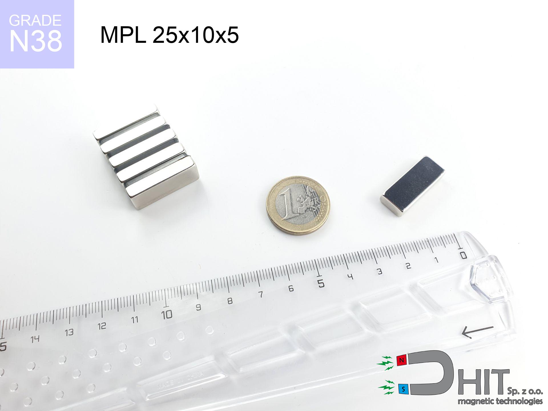
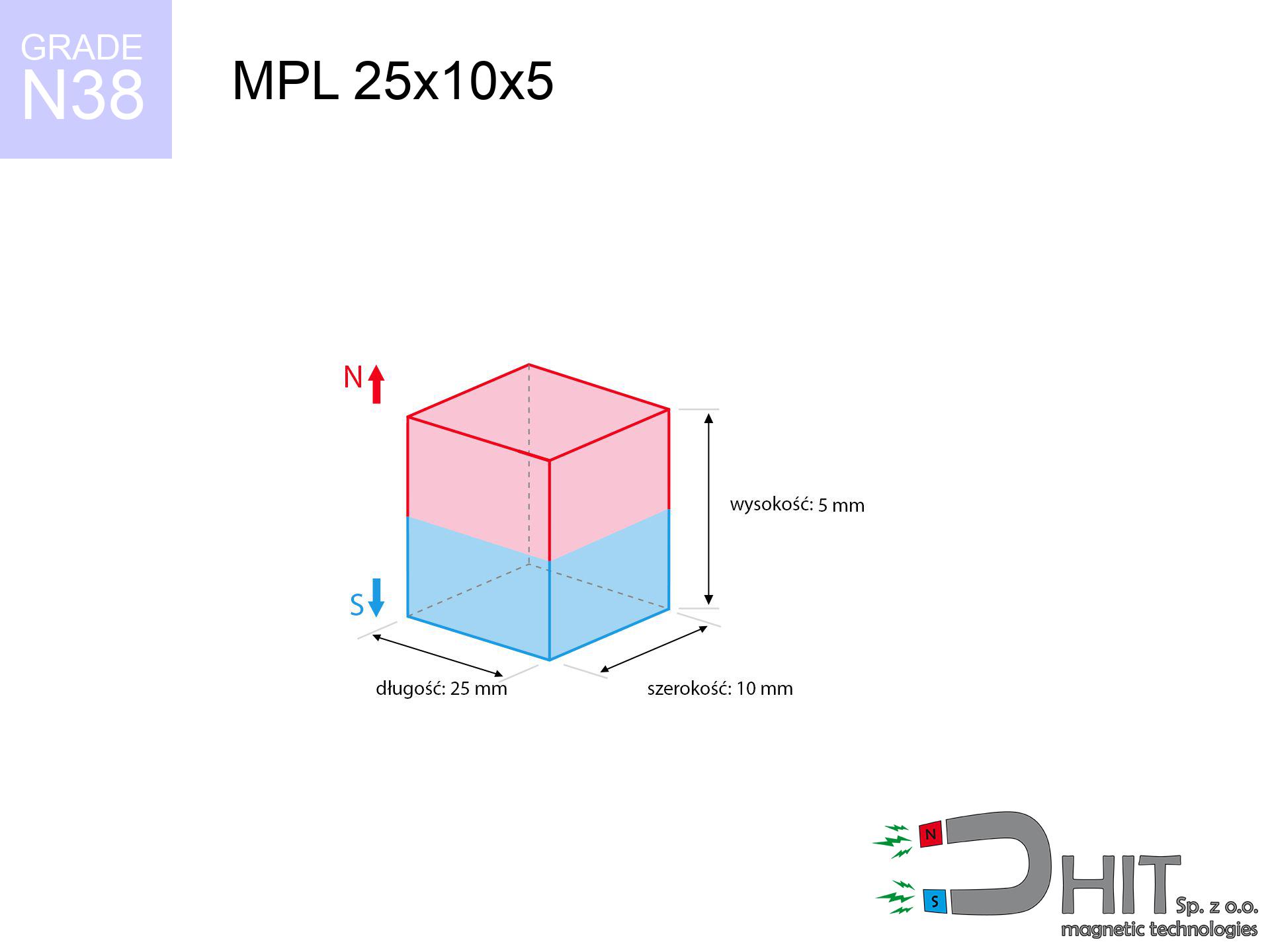
MPL 25x10x5 / N38 - lamellar magnet
lamellar magnet
Catalog no 020135
GTIN/EAN: 5906301811411
length
25 mm [±0,1 mm]
Width
10 mm [±0,1 mm]
Height
5 mm [±0,1 mm]
Weight
9.38 g
Magnetization Direction
↑ axial
Load capacity
7.49 kg / 73.45 N
Magnetic Induction
337.05 mT / 3371 Gs
Coating
[NiCuNi] Nickel
4.66 ZŁ with VAT / pcs + price for transport
3.79 ZŁ net + 23% VAT / pcs
bulk discounts:
Need more?Engineering report for this magnet
Full PDF analysis: pull and shear force, effect of distance, temperature and plate thickness, safety distances and the demagnetization curve.
Give us a call
+48 22 499 98 98
or get in touch using
contact form
the contact page.
Specifications as well as structure of magnets can be calculated with our
modular calculator.
Same-day shipping for orders placed before 14:00.
Technical of the product - MPL 25x10x5 / N38 - lamellar magnet
Specification / characteristics - MPL 25x10x5 / N38 - lamellar magnet
| properties | values |
|---|---|
| Cat. no. | 020135 |
| GTIN/EAN | 5906301811411 |
| Production/Distribution | Dhit sp. z o.o. |
| Country of origin | Poland / China / Germany |
| Customs code | 85059029 |
| length | 25 mm [±0,1 mm] |
| Width | 10 mm [±0,1 mm] |
| Height | 5 mm [±0,1 mm] |
| Weight | 9.38 g |
| Magnetization Direction | ↑ axial |
| Load capacity ~ ? | 7.49 kg / 73.45 N |
| Magnetic Induction ~ ? | 337.05 mT / 3371 Gs |
| Coating | [NiCuNi] Nickel |
| Manufacturing Tolerance | ±0.1 mm |
Magnetic properties of material N38
| properties | values | units |
|---|---|---|
| remenance Br [min. - max.] ? | 12.2-12.6 | kGs |
| remenance Br [min. - max.] ? | 1220-1260 | mT |
| coercivity bHc ? | 10.8-11.5 | kOe |
| coercivity bHc ? | 860-915 | kA/m |
| actual internal force iHc | ≥ 12 | kOe |
| actual internal force iHc | ≥ 955 | kA/m |
| energy density [min. - max.] ? | 36-38 | BH max MGOe |
| energy density [min. - max.] ? | 287-303 | BH max KJ/m |
| max. temperature ? | ≤ 80 | °C |
Physical properties of sintered neodymium magnets Nd2Fe14B at 20°C
| properties | values | units |
|---|---|---|
| Vickers hardness | ≥550 | Hv |
| Density | ≥7.4 | g/cm3 |
| Curie Temperature TC | 312 - 380 | °C |
| Curie Temperature TF | 593 - 716 | °F |
| Specific resistance | 150 | μΩ⋅cm |
| Bending strength | 250 | MPa |
| Compressive strength | 1000~1100 | MPa |
| Thermal expansion parallel (∥) to orientation (M) | (3-4) x 10-6 | °C-1 |
| Thermal expansion perpendicular (⊥) to orientation (M) | -(1-3) x 10-6 | °C-1 |
| Young's modulus | 1.7 x 10⁴ | kg/mm² |
Physical simulation of the magnet - data
These values represent the direct effect of a engineering simulation. Values rely on models for the material Nd2Fe14B. Actual conditions may differ from theoretical values. Treat these data as a supplementary guide during assembly planning.
Table 1: Static pull force (force vs distance) - characteristics
MPL 25x10x5 / N38
| Distance (mm) | Induction (Gauss) / mT | Pull Force (kg/lbs/g/N) | Risk Status |
|---|---|---|---|
| 0 mm |
3369 Gs
336.9 mT
|
7.49 kg / 16.51 LBS
7490.0 g / 73.5 N
|
warning |
| 1 mm |
2932 Gs
293.2 mT
|
5.67 kg / 12.51 LBS
5673.2 g / 55.7 N
|
warning |
| 2 mm |
2479 Gs
247.9 mT
|
4.06 kg / 8.94 LBS
4056.9 g / 39.8 N
|
warning |
| 3 mm |
2065 Gs
206.5 mT
|
2.81 kg / 6.21 LBS
2814.7 g / 27.6 N
|
warning |
| 5 mm |
1419 Gs
141.9 mT
|
1.33 kg / 2.93 LBS
1328.6 g / 13.0 N
|
low risk |
| 10 mm |
603 Gs
60.3 mT
|
0.24 kg / 0.53 LBS
240.3 g / 2.4 N
|
low risk |
| 15 mm |
296 Gs
29.6 mT
|
0.06 kg / 0.13 LBS
57.8 g / 0.6 N
|
low risk |
| 20 mm |
162 Gs
16.2 mT
|
0.02 kg / 0.04 LBS
17.4 g / 0.2 N
|
low risk |
| 30 mm |
62 Gs
6.2 mT
|
0.00 kg / 0.01 LBS
2.5 g / 0.0 N
|
low risk |
| 50 mm |
16 Gs
1.6 mT
|
0.00 kg / 0.00 LBS
0.2 g / 0.0 N
|
low risk |
Table 2: Shear load (wall)
MPL 25x10x5 / N38
| Distance (mm) | Friction coefficient | Pull Force (kg/lbs/g/N) |
|---|---|---|
| 0 mm | Stal (~0.2) |
1.50 kg / 3.30 LBS
1498.0 g / 14.7 N
|
| 1 mm | Stal (~0.2) |
1.13 kg / 2.50 LBS
1134.0 g / 11.1 N
|
| 2 mm | Stal (~0.2) |
0.81 kg / 1.79 LBS
812.0 g / 8.0 N
|
| 3 mm | Stal (~0.2) |
0.56 kg / 1.24 LBS
562.0 g / 5.5 N
|
| 5 mm | Stal (~0.2) |
0.27 kg / 0.59 LBS
266.0 g / 2.6 N
|
| 10 mm | Stal (~0.2) |
0.05 kg / 0.11 LBS
48.0 g / 0.5 N
|
| 15 mm | Stal (~0.2) |
0.01 kg / 0.03 LBS
12.0 g / 0.1 N
|
| 20 mm | Stal (~0.2) |
0.00 kg / 0.01 LBS
4.0 g / 0.0 N
|
| 30 mm | Stal (~0.2) |
0.00 kg / 0.00 LBS
0.0 g / 0.0 N
|
| 50 mm | Stal (~0.2) |
0.00 kg / 0.00 LBS
0.0 g / 0.0 N
|
Table 3: Wall mounting (shearing) - behavior on slippery surfaces
MPL 25x10x5 / N38
| Surface type | Friction coefficient / % Mocy | Max load (kg/lbs/g/N) |
|---|---|---|
| Raw steel |
µ = 0.3
30% Nominalnej Siły
|
2.25 kg / 4.95 LBS
2247.0 g / 22.0 N
|
| Painted steel (standard) |
µ = 0.2
20% Nominalnej Siły
|
1.50 kg / 3.30 LBS
1498.0 g / 14.7 N
|
| Oily/slippery steel |
µ = 0.1
10% Nominalnej Siły
|
0.75 kg / 1.65 LBS
749.0 g / 7.3 N
|
| Magnet with anti-slip rubber |
µ = 0.5
50% Nominalnej Siły
|
3.75 kg / 8.26 LBS
3745.0 g / 36.7 N
|
Table 4: Steel thickness (substrate influence) - sheet metal selection
MPL 25x10x5 / N38
| Steel thickness (mm) | % power | Real pull force (kg/lbs/g/N) |
|---|---|---|
| 0.5 mm |
|
0.75 kg / 1.65 LBS
749.0 g / 7.3 N
|
| 1 mm |
|
1.87 kg / 4.13 LBS
1872.5 g / 18.4 N
|
| 2 mm |
|
3.75 kg / 8.26 LBS
3745.0 g / 36.7 N
|
| 3 mm |
|
5.62 kg / 12.38 LBS
5617.5 g / 55.1 N
|
| 5 mm |
|
7.49 kg / 16.51 LBS
7490.0 g / 73.5 N
|
| 10 mm |
|
7.49 kg / 16.51 LBS
7490.0 g / 73.5 N
|
| 11 mm |
|
7.49 kg / 16.51 LBS
7490.0 g / 73.5 N
|
| 12 mm |
|
7.49 kg / 16.51 LBS
7490.0 g / 73.5 N
|
Table 5: Thermal stability (material behavior) - thermal limit
MPL 25x10x5 / N38
| Ambient temp. (°C) | Power loss | Remaining pull (kg/lbs/g/N) | Status |
|---|---|---|---|
| 20 °C | 0.0% |
7.49 kg / 16.51 LBS
7490.0 g / 73.5 N
|
OK |
| 40 °C | -2.2% |
7.33 kg / 16.15 LBS
7325.2 g / 71.9 N
|
OK |
| 60 °C | -4.4% |
7.16 kg / 15.79 LBS
7160.4 g / 70.2 N
|
|
| 80 °C | -6.6% |
7.00 kg / 15.42 LBS
6995.7 g / 68.6 N
|
|
| 100 °C | -28.8% |
5.33 kg / 11.76 LBS
5332.9 g / 52.3 N
|
Table 6: Two magnets (repulsion) - field collision
MPL 25x10x5 / N38
| Gap (mm) | Attraction (kg/lbs) (N-S) | Sliding Force (kg/lbs/g/N) | Repulsion (kg/lbs) (N-N) |
|---|---|---|---|
| 0 mm |
17.49 kg / 38.57 LBS
4 785 Gs
|
2.62 kg / 5.78 LBS
2624 g / 25.7 N
|
N/A |
| 1 mm |
15.37 kg / 33.89 LBS
6 316 Gs
|
2.31 kg / 5.08 LBS
2306 g / 22.6 N
|
13.84 kg / 30.50 LBS
~0 Gs
|
| 2 mm |
13.25 kg / 29.21 LBS
5 864 Gs
|
1.99 kg / 4.38 LBS
1987 g / 19.5 N
|
11.92 kg / 26.29 LBS
~0 Gs
|
| 3 mm |
11.26 kg / 24.83 LBS
5 407 Gs
|
1.69 kg / 3.72 LBS
1690 g / 16.6 N
|
10.14 kg / 22.35 LBS
~0 Gs
|
| 5 mm |
7.91 kg / 17.44 LBS
4 531 Gs
|
1.19 kg / 2.62 LBS
1187 g / 11.6 N
|
7.12 kg / 15.70 LBS
~0 Gs
|
| 10 mm |
3.10 kg / 6.84 LBS
2 838 Gs
|
0.47 kg / 1.03 LBS
465 g / 4.6 N
|
2.79 kg / 6.16 LBS
~0 Gs
|
| 20 mm |
0.56 kg / 1.24 LBS
1 207 Gs
|
0.08 kg / 0.19 LBS
84 g / 0.8 N
|
0.51 kg / 1.11 LBS
~0 Gs
|
| 50 mm |
0.01 kg / 0.03 LBS
194 Gs
|
0.00 kg / 0.00 LBS
2 g / 0.0 N
|
0.01 kg / 0.03 LBS
~0 Gs
|
| 60 mm |
0.01 kg / 0.01 LBS
124 Gs
|
0.00 kg / 0.00 LBS
1 g / 0.0 N
|
0.00 kg / 0.00 LBS
~0 Gs
|
| 70 mm |
0.00 kg / 0.01 LBS
84 Gs
|
0.00 kg / 0.00 LBS
0 g / 0.0 N
|
0.00 kg / 0.00 LBS
~0 Gs
|
| 80 mm |
0.00 kg / 0.00 LBS
59 Gs
|
0.00 kg / 0.00 LBS
0 g / 0.0 N
|
0.00 kg / 0.00 LBS
~0 Gs
|
| 90 mm |
0.00 kg / 0.00 LBS
43 Gs
|
0.00 kg / 0.00 LBS
0 g / 0.0 N
|
0.00 kg / 0.00 LBS
~0 Gs
|
| 100 mm |
0.00 kg / 0.00 LBS
32 Gs
|
0.00 kg / 0.00 LBS
0 g / 0.0 N
|
0.00 kg / 0.00 LBS
~0 Gs
|
Table 7: Protective zones (electronics) - warnings
MPL 25x10x5 / N38
| Object / Device | Limit (Gauss) / mT | Safe distance |
|---|---|---|
| Pacemaker | 5 Gs (0.5 mT) | 8.0 cm |
| Hearing aid | 10 Gs (1.0 mT) | 6.0 cm |
| Timepiece | 20 Gs (2.0 mT) | 5.0 cm |
| Mobile device | 40 Gs (4.0 mT) | 4.0 cm |
| Car key | 50 Gs (5.0 mT) | 3.5 cm |
| Payment card | 400 Gs (40.0 mT) | 1.5 cm |
| HDD hard drive | 600 Gs (60.0 mT) | 1.5 cm |
Table 8: Dynamics (kinetic energy) - warning
MPL 25x10x5 / N38
| Start from (mm) | Speed (km/h) | Energy (J) | Predicted outcome |
|---|---|---|---|
| 10 mm |
29.06 km/h
(8.07 m/s)
|
0.31 J | |
| 30 mm |
49.37 km/h
(13.71 m/s)
|
0.88 J | |
| 50 mm |
63.73 km/h
(17.70 m/s)
|
1.47 J | |
| 100 mm |
90.12 km/h
(25.03 m/s)
|
2.94 J |
Table 9: Anti-corrosion coating durability
MPL 25x10x5 / N38
| Technical parameter | Value / Description |
|---|---|
| Coating type | [NiCuNi] Nickel |
| Layer structure | Nickel - Copper - Nickel |
| Layer thickness | 10-20 µm |
| Salt spray test (SST) ? | 24 h |
| Recommended environment | Indoors only (dry) |
Table 10: Electrical data (Pc)
MPL 25x10x5 / N38
| Parameter | Value | SI Unit / Description |
|---|---|---|
| Magnetic Flux | 8 245 Mx | 82.5 µWb |
| Pc Coefficient | 0.38 | Low (Flat) |
Table 11: Physics of underwater searching
MPL 25x10x5 / N38
| Environment | Effective steel pull | Effect |
|---|---|---|
| Air (land) | 7.49 kg | Standard |
| Water (riverbed) |
8.58 kg
(+1.09 kg buoyancy gain)
|
+14.5% |
1. Sliding resistance
*Warning: On a vertical wall, the magnet retains merely approx. 20-30% of its nominal pull.
2. Plate thickness effect
*Thin steel (e.g. computer case) significantly weakens the holding force.
3. Power loss vs temp
*For N38 material, the safety limit is 80°C.
4. Demagnetization curve and operating point (B-H)
chart generated for the permeance coefficient Pc (Permeance Coefficient) = 0.38
The chart above illustrates the magnetic characteristics of the material within the second quadrant of the hysteresis loop. The solid red line represents the demagnetization curve (material potential), while the dashed blue line is the load line based on the magnet's geometry. The Pc (Permeance Coefficient), also known as the load line slope, is a dimensionless value that describes the relationship between the magnet's shape and its magnetic stability. The intersection of these two lines (the black dot) is the operating point — it determines the actual magnetic flux density generated by the magnet in this specific configuration. A higher Pc value means the magnet is more 'slender' (tall relative to its area), resulting in a higher operating point and better resistance to irreversible demagnetization caused by external fields or temperature. A value of 0.42 is relatively low (typical for flat magnets), meaning the operating point is closer to the 'knee' of the curve — caution is advised when operating at temperatures near the maximum limit to avoid strength loss.
Elemental analysis
| iron (Fe) | 64% – 68% |
| neodymium (Nd) | 29% – 32% |
| boron (B) | 1.1% – 1.2% |
| dysprosium (Dy) | 0.5% – 2.0% |
| coating (Ni-Cu-Ni) | < 0.05% |
Ecology and recycling (GPSR)
| recyclability (EoL) | 100% |
| recycled raw materials | ~10% (pre-cons) |
| carbon footprint | low / zredukowany |
| waste code (EWC) | 16 02 16 |
View also offers


![UMP 97x40 [M8+M10] GW F300 kg / N38 - search holder](https://cdn3.dhit.pl/graphics/products/ump97x40-m8+m10-gw-f-300-kg-kic.jpg "UMP 97x40 [M8+M10] GW F300 kg / N38 - search holder")
Strengths and weaknesses of neodymium magnets.
Strengths
- They retain attractive force for nearly 10 years – the loss is just ~1% (according to analyses),
- Neodymium magnets are remarkably resistant to loss of magnetic properties caused by external field sources,
- The use of an refined coating of noble metals (nickel, gold, silver) causes the element to look better,
- Neodymium magnets achieve maximum magnetic induction on a their surface, which ensures high operational effectiveness,
- Neodymium magnets are characterized by extremely high magnetic induction on the magnet surface and are able to act (depending on the shape) even at a temperature of 230°C or more...
- Thanks to flexibility in constructing and the ability to customize to specific needs,
- Fundamental importance in innovative solutions – they are used in data components, drive modules, medical devices, and industrial machines.
- Compactness – despite small sizes they generate large force, making them ideal for precision applications
Limitations
- To avoid cracks upon strong impacts, we recommend using special steel holders. Such a solution protects the magnet and simultaneously increases its durability.
- We warn that neodymium magnets can lose their strength at high temperatures. To prevent this, we suggest our specialized [AH] magnets, which work effectively even at 230°C.
- Magnets exposed to a humid environment can corrode. Therefore when using outdoors, we suggest using water-impermeable magnets made of rubber, plastic or other material protecting against moisture
- Due to limitations in producing threads and complex shapes in magnets, we propose using casing - magnetic mechanism.
- Potential hazard resulting from small fragments of magnets are risky, when accidentally swallowed, which becomes key in the context of child safety. Furthermore, small elements of these products can disrupt the diagnostic process medical when they are in the body.
- Higher cost of purchase is one of the disadvantages compared to ceramic magnets, especially in budget applications
Holding force characteristics
Maximum lifting capacity of the magnet – what contributes to it?
- on a plate made of structural steel, optimally conducting the magnetic field
- possessing a massiveness of min. 10 mm to ensure full flux closure
- with a plane perfectly flat
- under conditions of gap-free contact (metal-to-metal)
- for force applied at a right angle (pull-off, not shear)
- at ambient temperature room level
Lifting capacity in real conditions – factors
- Space between surfaces – even a fraction of a millimeter of distance (caused e.g. by varnish or dirt) significantly weakens the magnet efficiency, often by half at just 0.5 mm.
- Angle of force application – maximum parameter is obtained only during perpendicular pulling. The resistance to sliding of the magnet along the surface is standardly many times smaller (approx. 1/5 of the lifting capacity).
- Wall thickness – the thinner the sheet, the weaker the hold. Part of the magnetic field penetrates through instead of converting into lifting capacity.
- Plate material – low-carbon steel gives the best results. Alloy admixtures decrease magnetic permeability and holding force.
- Surface condition – smooth surfaces guarantee perfect abutment, which improves force. Uneven metal reduce efficiency.
- Heat – neodymium magnets have a negative temperature coefficient. At higher temperatures they lose power, and in frost they can be stronger (up to a certain limit).
Holding force was tested on the plate surface of 20 mm thickness, when a perpendicular force was applied, in contrast under attempts to slide the magnet the lifting capacity is smaller. In addition, even a small distance between the magnet and the plate reduces the holding force.
Safe handling of neodymium magnets
Fire warning
Combustion risk: Rare earth powder is explosive. Do not process magnets in home conditions as this may cause fire.
Cards and drives
Avoid bringing magnets near a wallet, laptop, or TV. The magnetism can destroy these devices and erase data from cards.
Shattering risk
Despite the nickel coating, neodymium is delicate and cannot withstand shocks. Do not hit, as the magnet may shatter into sharp, dangerous pieces.
Powerful field
Use magnets with awareness. Their powerful strength can surprise even experienced users. Plan your moves and do not underestimate their force.
Thermal limits
Monitor thermal conditions. Heating the magnet above 80 degrees Celsius will destroy its properties and strength.
Warning for heart patients
Health Alert: Neodymium magnets can turn off heart devices and defibrillators. Stay away if you have electronic implants.
Metal Allergy
Warning for allergy sufferers: The nickel-copper-nickel coating consists of nickel. If redness happens, cease working with magnets and use protective gear.
GPS and phone interference
An intense magnetic field interferes with the functioning of magnetometers in smartphones and navigation systems. Do not bring magnets close to a device to avoid damaging the sensors.
Crushing risk
Large magnets can crush fingers instantly. Never put your hand between two strong magnets.
Choking Hazard
Only for adults. Tiny parts can be swallowed, causing severe trauma. Store away from kids and pets.
Tabela kosztu i czasu dostawy
Płatność przed wysyłką:

GLS kurier
Przesyłka będzie u Ciebie za 2-3 dni
14.99 ZŁ

InPost Paczkomaty 24/7
Przesyłka będzie u Ciebie za 1-2 dni
12.30 ZŁ
Płatność przy odbiorze (pobranie):
GLS kurier
Przesyłka będzie u Ciebie za 1-2 dni
23.00 ZŁ
Rate the product
Your rating