
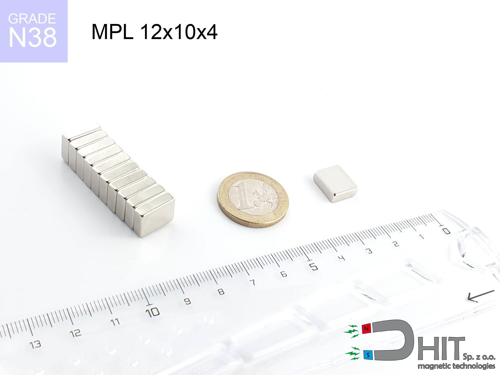
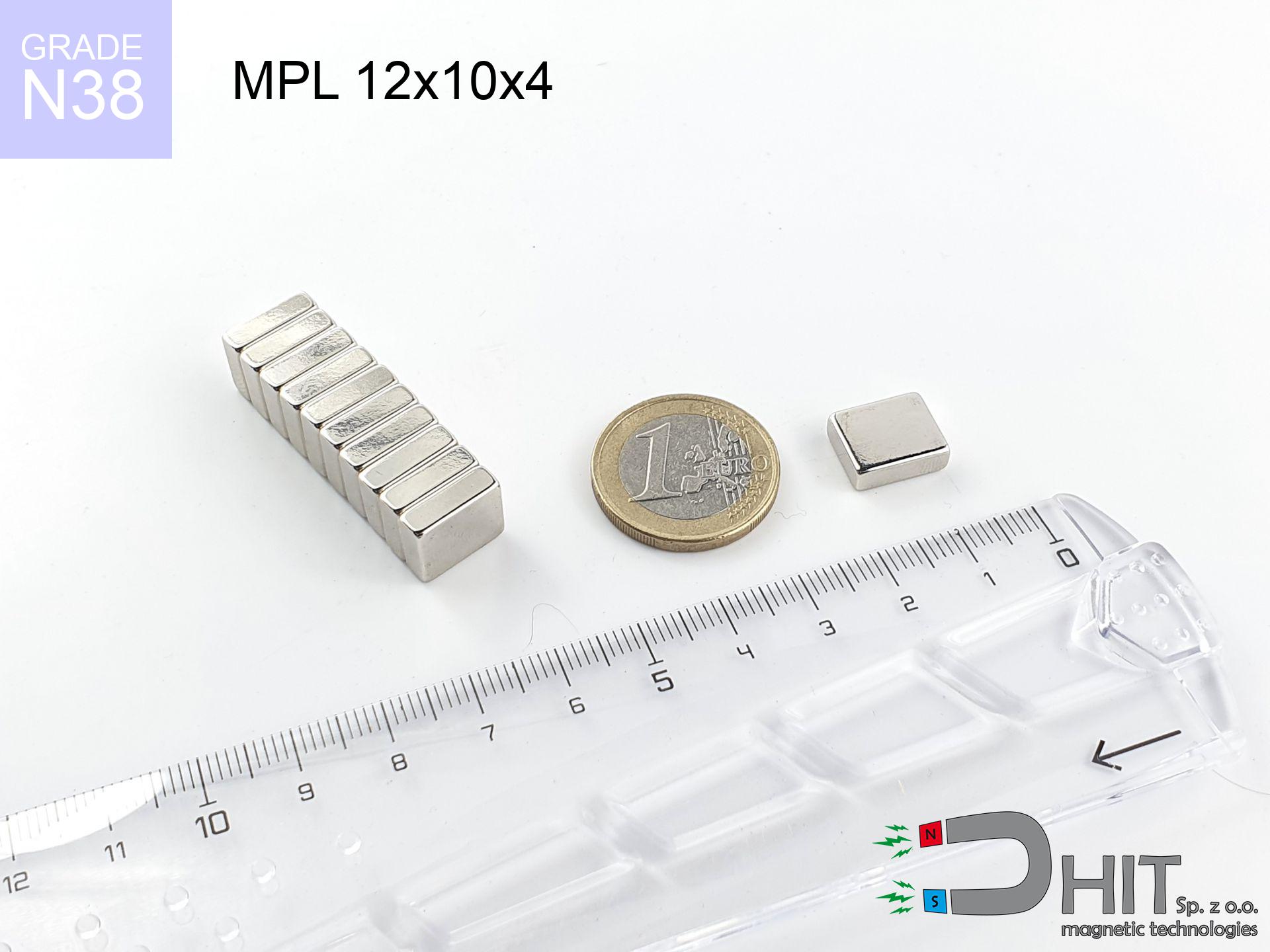
MPL 12x10x4 / N38 - lamellar magnet
lamellar magnet
Catalog no 020118
GTIN/EAN: 5906301811244
length
12 mm [±0,1 mm]
Width
10 mm [±0,1 mm]
Height
4 mm [±0,1 mm]
Weight
3.6 g
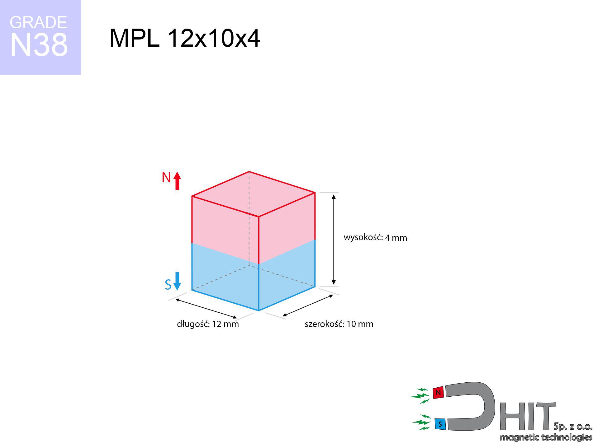
Magnetization Direction
↑ axial
Load capacity
3.45 kg / 33.88 N
Magnetic Induction
340.59 mT / 3406 Gs
Coating
[NiCuNi] Nickel
1.697 ZŁ with VAT / pcs + price for transport
1.380 ZŁ net + 23% VAT / pcs
bulk discounts:
Need more?Engineering report for this magnet
Full PDF analysis: pull and shear force, effect of distance, temperature and plate thickness, safety distances and the demagnetization curve.
Call us now
+48 22 499 98 98
if you prefer contact us by means of
contact form
the contact page.
Lifting power along with shape of a neodymium magnet can be verified on our
online calculation tool.
Same-day shipping for orders placed before 14:00.
Technical of the product - MPL 12x10x4 / N38 - lamellar magnet
Specification / characteristics - MPL 12x10x4 / N38 - lamellar magnet
| properties | values |
|---|---|
| Cat. no. | 020118 |
| GTIN/EAN | 5906301811244 |
| Production/Distribution | Dhit sp. z o.o. |
| Country of origin | Poland / China / Germany |
| Customs code | 85059029 |
| length | 12 mm [±0,1 mm] |
| Width | 10 mm [±0,1 mm] |
| Height | 4 mm [±0,1 mm] |
| Weight | 3.6 g |
| Magnetization Direction | ↑ axial |
| Load capacity ~ ? | 3.45 kg / 33.88 N |
| Magnetic Induction ~ ? | 340.59 mT / 3406 Gs |
| Coating | [NiCuNi] Nickel |
| Manufacturing Tolerance | ±0.1 mm |
Magnetic properties of material N38
| properties | values | units |
|---|---|---|
| remenance Br [min. - max.] ? | 12.2-12.6 | kGs |
| remenance Br [min. - max.] ? | 1220-1260 | mT |
| coercivity bHc ? | 10.8-11.5 | kOe |
| coercivity bHc ? | 860-915 | kA/m |
| actual internal force iHc | ≥ 12 | kOe |
| actual internal force iHc | ≥ 955 | kA/m |
| energy density [min. - max.] ? | 36-38 | BH max MGOe |
| energy density [min. - max.] ? | 287-303 | BH max KJ/m |
| max. temperature ? | ≤ 80 | °C |
Physical properties of sintered neodymium magnets Nd2Fe14B at 20°C
| properties | values | units |
|---|---|---|
| Vickers hardness | ≥550 | Hv |
| Density | ≥7.4 | g/cm3 |
| Curie Temperature TC | 312 - 380 | °C |
| Curie Temperature TF | 593 - 716 | °F |
| Specific resistance | 150 | μΩ⋅cm |
| Bending strength | 250 | MPa |
| Compressive strength | 1000~1100 | MPa |
| Thermal expansion parallel (∥) to orientation (M) | (3-4) x 10-6 | °C-1 |
| Thermal expansion perpendicular (⊥) to orientation (M) | -(1-3) x 10-6 | °C-1 |
| Young's modulus | 1.7 x 10⁴ | kg/mm² |
Physical simulation of the assembly - report
Presented values represent the outcome of a engineering analysis. Results were calculated on models for the material Nd2Fe14B. Real-world parameters might slightly deviate from the simulation results. Use these data as a supplementary guide for designers.
Table 1: Static pull force (force vs distance) - characteristics
MPL 12x10x4 / N38
| Distance (mm) | Induction (Gauss) / mT | Pull Force (kg/lbs/g/N) | Risk Status |
|---|---|---|---|
| 0 mm |
3404 Gs
340.4 mT
|
3.45 kg / 7.61 pounds
3450.0 g / 33.8 N
|
strong |
| 1 mm |
2920 Gs
292.0 mT
|
2.54 kg / 5.60 pounds
2538.8 g / 24.9 N
|
strong |
| 2 mm |
2399 Gs
239.9 mT
|
1.71 kg / 3.78 pounds
1713.7 g / 16.8 N
|
weak grip |
| 3 mm |
1919 Gs
191.9 mT
|
1.10 kg / 2.42 pounds
1096.3 g / 10.8 N
|
weak grip |
| 5 mm |
1190 Gs
119.0 mT
|
0.42 kg / 0.93 pounds
421.6 g / 4.1 N
|
weak grip |
| 10 mm |
392 Gs
39.2 mT
|
0.05 kg / 0.10 pounds
45.7 g / 0.4 N
|
weak grip |
| 15 mm |
162 Gs
16.2 mT
|
0.01 kg / 0.02 pounds
7.8 g / 0.1 N
|
weak grip |
| 20 mm |
80 Gs
8.0 mT
|
0.00 kg / 0.00 pounds
1.9 g / 0.0 N
|
weak grip |
| 30 mm |
27 Gs
2.7 mT
|
0.00 kg / 0.00 pounds
0.2 g / 0.0 N
|
weak grip |
| 50 mm |
7 Gs
0.7 mT
|
0.00 kg / 0.00 pounds
0.0 g / 0.0 N
|
weak grip |
Table 2: Sliding capacity (vertical surface)
MPL 12x10x4 / N38
| Distance (mm) | Friction coefficient | Pull Force (kg/lbs/g/N) |
|---|---|---|
| 0 mm | Stal (~0.2) |
0.69 kg / 1.52 pounds
690.0 g / 6.8 N
|
| 1 mm | Stal (~0.2) |
0.51 kg / 1.12 pounds
508.0 g / 5.0 N
|
| 2 mm | Stal (~0.2) |
0.34 kg / 0.75 pounds
342.0 g / 3.4 N
|
| 3 mm | Stal (~0.2) |
0.22 kg / 0.49 pounds
220.0 g / 2.2 N
|
| 5 mm | Stal (~0.2) |
0.08 kg / 0.19 pounds
84.0 g / 0.8 N
|
| 10 mm | Stal (~0.2) |
0.01 kg / 0.02 pounds
10.0 g / 0.1 N
|
| 15 mm | Stal (~0.2) |
0.00 kg / 0.00 pounds
2.0 g / 0.0 N
|
| 20 mm | Stal (~0.2) |
0.00 kg / 0.00 pounds
0.0 g / 0.0 N
|
| 30 mm | Stal (~0.2) |
0.00 kg / 0.00 pounds
0.0 g / 0.0 N
|
| 50 mm | Stal (~0.2) |
0.00 kg / 0.00 pounds
0.0 g / 0.0 N
|
Table 3: Wall mounting (sliding) - behavior on slippery surfaces
MPL 12x10x4 / N38
| Surface type | Friction coefficient / % Mocy | Max load (kg/lbs/g/N) |
|---|---|---|
| Raw steel |
µ = 0.3
30% Nominalnej Siły
|
1.04 kg / 2.28 pounds
1035.0 g / 10.2 N
|
| Painted steel (standard) |
µ = 0.2
20% Nominalnej Siły
|
0.69 kg / 1.52 pounds
690.0 g / 6.8 N
|
| Oily/slippery steel |
µ = 0.1
10% Nominalnej Siły
|
0.35 kg / 0.76 pounds
345.0 g / 3.4 N
|
| Magnet with anti-slip rubber |
µ = 0.5
50% Nominalnej Siły
|
1.73 kg / 3.80 pounds
1725.0 g / 16.9 N
|
Table 4: Steel thickness (substrate influence) - sheet metal selection
MPL 12x10x4 / N38
| Steel thickness (mm) | % power | Real pull force (kg/lbs/g/N) |
|---|---|---|
| 0.5 mm |
|
0.35 kg / 0.76 pounds
345.0 g / 3.4 N
|
| 1 mm |
|
0.86 kg / 1.90 pounds
862.5 g / 8.5 N
|
| 2 mm |
|
1.73 kg / 3.80 pounds
1725.0 g / 16.9 N
|
| 3 mm |
|
2.59 kg / 5.70 pounds
2587.5 g / 25.4 N
|
| 5 mm |
|
3.45 kg / 7.61 pounds
3450.0 g / 33.8 N
|
| 10 mm |
|
3.45 kg / 7.61 pounds
3450.0 g / 33.8 N
|
| 11 mm |
|
3.45 kg / 7.61 pounds
3450.0 g / 33.8 N
|
| 12 mm |
|
3.45 kg / 7.61 pounds
3450.0 g / 33.8 N
|
Table 5: Thermal stability (material behavior) - thermal limit
MPL 12x10x4 / N38
| Ambient temp. (°C) | Power loss | Remaining pull (kg/lbs/g/N) | Status |
|---|---|---|---|
| 20 °C | 0.0% |
3.45 kg / 7.61 pounds
3450.0 g / 33.8 N
|
OK |
| 40 °C | -2.2% |
3.37 kg / 7.44 pounds
3374.1 g / 33.1 N
|
OK |
| 60 °C | -4.4% |
3.30 kg / 7.27 pounds
3298.2 g / 32.4 N
|
|
| 80 °C | -6.6% |
3.22 kg / 7.10 pounds
3222.3 g / 31.6 N
|
|
| 100 °C | -28.8% |
2.46 kg / 5.42 pounds
2456.4 g / 24.1 N
|
Table 6: Two magnets (repulsion) - forces in the system
MPL 12x10x4 / N38
| Gap (mm) | Attraction (kg/lbs) (N-S) | Shear Strength (kg/lbs/g/N) | Repulsion (kg/lbs) (N-N) |
|---|---|---|---|
| 0 mm |
8.57 kg / 18.90 pounds
4 915 Gs
|
1.29 kg / 2.84 pounds
1286 g / 12.6 N
|
N/A |
| 1 mm |
7.46 kg / 16.44 pounds
6 349 Gs
|
1.12 kg / 2.47 pounds
1118 g / 11.0 N
|
6.71 kg / 14.79 pounds
~0 Gs
|
| 2 mm |
6.31 kg / 13.91 pounds
5 841 Gs
|
0.95 kg / 2.09 pounds
946 g / 9.3 N
|
5.68 kg / 12.52 pounds
~0 Gs
|
| 3 mm |
5.23 kg / 11.53 pounds
5 317 Gs
|
0.78 kg / 1.73 pounds
784 g / 7.7 N
|
4.71 kg / 10.37 pounds
~0 Gs
|
| 5 mm |
3.42 kg / 7.55 pounds
4 302 Gs
|
0.51 kg / 1.13 pounds
513 g / 5.0 N
|
3.08 kg / 6.79 pounds
~0 Gs
|
| 10 mm |
1.05 kg / 2.31 pounds
2 380 Gs
|
0.16 kg / 0.35 pounds
157 g / 1.5 N
|
0.94 kg / 2.08 pounds
~0 Gs
|
| 20 mm |
0.11 kg / 0.25 pounds
784 Gs
|
0.02 kg / 0.04 pounds
17 g / 0.2 N
|
0.10 kg / 0.23 pounds
~0 Gs
|
| 50 mm |
0.00 kg / 0.00 pounds
90 Gs
|
0.00 kg / 0.00 pounds
0 g / 0.0 N
|
0.00 kg / 0.00 pounds
~0 Gs
|
| 60 mm |
0.00 kg / 0.00 pounds
55 Gs
|
0.00 kg / 0.00 pounds
0 g / 0.0 N
|
0.00 kg / 0.00 pounds
~0 Gs
|
| 70 mm |
0.00 kg / 0.00 pounds
36 Gs
|
0.00 kg / 0.00 pounds
0 g / 0.0 N
|
0.00 kg / 0.00 pounds
~0 Gs
|
| 80 mm |
0.00 kg / 0.00 pounds
25 Gs
|
0.00 kg / 0.00 pounds
0 g / 0.0 N
|
0.00 kg / 0.00 pounds
~0 Gs
|
| 90 mm |
0.00 kg / 0.00 pounds
18 Gs
|
0.00 kg / 0.00 pounds
0 g / 0.0 N
|
0.00 kg / 0.00 pounds
~0 Gs
|
| 100 mm |
0.00 kg / 0.00 pounds
13 Gs
|
0.00 kg / 0.00 pounds
0 g / 0.0 N
|
0.00 kg / 0.00 pounds
~0 Gs
|
Table 7: Protective zones (electronics) - precautionary measures
MPL 12x10x4 / N38
| Object / Device | Limit (Gauss) / mT | Safe distance |
|---|---|---|
| Pacemaker | 5 Gs (0.5 mT) | 6.0 cm |
| Hearing aid | 10 Gs (1.0 mT) | 4.5 cm |
| Mechanical watch | 20 Gs (2.0 mT) | 3.5 cm |
| Mobile device | 40 Gs (4.0 mT) | 3.0 cm |
| Car key | 50 Gs (5.0 mT) | 2.5 cm |
| Payment card | 400 Gs (40.0 mT) | 1.0 cm |
| HDD hard drive | 600 Gs (60.0 mT) | 1.0 cm |
Table 8: Dynamics (cracking risk) - collision effects
MPL 12x10x4 / N38
| Start from (mm) | Speed (km/h) | Energy (J) | Predicted outcome |
|---|---|---|---|
| 10 mm |
31.48 km/h
(8.74 m/s)
|
0.14 J | |
| 30 mm |
54.08 km/h
(15.02 m/s)
|
0.41 J | |
| 50 mm |
69.81 km/h
(19.39 m/s)
|
0.68 J | |
| 100 mm |
98.73 km/h
(27.42 m/s)
|
1.35 J |
Table 9: Coating parameters (durability)
MPL 12x10x4 / N38
| Technical parameter | Value / Description |
|---|---|
| Coating type | [NiCuNi] Nickel |
| Layer structure | Nickel - Copper - Nickel |
| Layer thickness | 10-20 µm |
| Salt spray test (SST) ? | 24 h |
| Recommended environment | Indoors only (dry) |
Table 10: Electrical data (Pc)
MPL 12x10x4 / N38
| Parameter | Value | SI Unit / Description |
|---|---|---|
| Magnetic Flux | 4 295 Mx | 42.9 µWb |
| Pc Coefficient | 0.43 | Low (Flat) |
Table 11: Submerged application
MPL 12x10x4 / N38
| Environment | Effective steel pull | Effect |
|---|---|---|
| Air (land) | 3.45 kg | Standard |
| Water (riverbed) |
3.95 kg
(+0.50 kg buoyancy gain)
|
+14.5% |
1. Sliding resistance
*Caution: On a vertical wall, the magnet retains merely approx. 20-30% of its nominal pull.
2. Steel thickness impact
*Thin steel (e.g. 0.5mm PC case) severely weakens the holding force.
3. Power loss vs temp
*For standard magnets, the max working temp is 80°C.
4. Demagnetization curve and operating point (B-H)
chart generated for the permeance coefficient Pc (Permeance Coefficient) = 0.43
This simulation demonstrates the magnetic stability of the selected magnet under specific geometric conditions. The solid red line represents the demagnetization curve (material potential), while the dashed blue line is the load line based on the magnet's geometry. The Pc (Permeance Coefficient), also known as the load line slope, is a dimensionless value that describes the relationship between the magnet's shape and its magnetic stability. The intersection of these two lines (the black dot) is the operating point — it determines the actual magnetic flux density generated by the magnet in this specific configuration. A higher Pc value means the magnet is more 'slender' (tall relative to its area), resulting in a higher operating point and better resistance to irreversible demagnetization caused by external fields or temperature. A value of 0.42 is relatively low (typical for flat magnets), meaning the operating point is closer to the 'knee' of the curve — caution is advised when operating at temperatures near the maximum limit to avoid strength loss.
Chemical composition
| iron (Fe) | 64% – 68% |
| neodymium (Nd) | 29% – 32% |
| boron (B) | 1.1% – 1.2% |
| dysprosium (Dy) | 0.5% – 2.0% |
| coating (Ni-Cu-Ni) | < 0.05% |
Sustainability
| recyclability (EoL) | 100% |
| recycled raw materials | ~10% (pre-cons) |
| carbon footprint | low / zredukowany |
| waste code (EWC) | 16 02 16 |
Other proposals


![UMH 16x5x32 [M4] / N38 - magnetic holder with hook](https://cdn3.dhit.pl/graphics/products/umh-16x5x32-m4-lak.jpg "UMH 16x5x32 [M4] / N38 - magnetic holder with hook")
![SM 25x225 [2xM8] / N52 - magnetic separator](https://cdn3.dhit.pl/graphics/products/sm-25x225-2xm8-lod.jpg "SM 25x225 [2xM8] / N52 - magnetic separator")
Pros as well as cons of rare earth magnets.
Strengths
- They have constant strength, and over nearly ten years their performance decreases symbolically – ~1% (in testing),
- They show high resistance to demagnetization induced by presence of other magnetic fields,
- In other words, due to the shiny finish of gold, the element becomes visually attractive,
- The surface of neodymium magnets generates a concentrated magnetic field – this is one of their assets,
- Made from properly selected components, these magnets show impressive resistance to high heat, enabling them to function (depending on their form) at temperatures up to 230°C and above...
- Possibility of individual shaping as well as modifying to concrete requirements,
- Wide application in future technologies – they are utilized in data components, electromotive mechanisms, advanced medical instruments, and other advanced devices.
- Thanks to efficiency per cm³, small magnets offer high operating force, in miniature format,
Weaknesses
- At very strong impacts they can crack, therefore we recommend placing them in strong housings. A metal housing provides additional protection against damage, as well as increases the magnet's durability.
- We warn that neodymium magnets can reduce their strength at high temperatures. To prevent this, we advise our specialized [AH] magnets, which work effectively even at 230°C.
- When exposed to humidity, magnets start to rust. For applications outside, it is recommended to use protective magnets, such as those in rubber or plastics, which prevent oxidation as well as corrosion.
- We suggest casing - magnetic holder, due to difficulties in realizing nuts inside the magnet and complex forms.
- Health risk related to microscopic parts of magnets are risky, when accidentally swallowed, which is particularly important in the context of child health protection. It is also worth noting that small elements of these magnets are able to be problematic in diagnostics medical in case of swallowing.
- High unit price – neodymium magnets cost more than other types of magnets (e.g. ferrite), which increases costs of application in large quantities
Pull force analysis
Maximum holding power of the magnet – what contributes to it?
- with the contact of a sheet made of special test steel, guaranteeing full magnetic saturation
- with a cross-section no less than 10 mm
- with an ideally smooth touching surface
- with total lack of distance (no impurities)
- under perpendicular force direction (90-degree angle)
- at ambient temperature approx. 20 degrees Celsius
Practical aspects of lifting capacity – factors
- Space between surfaces – even a fraction of a millimeter of separation (caused e.g. by varnish or dirt) drastically reduces the pulling force, often by half at just 0.5 mm.
- Loading method – declared lifting capacity refers to pulling vertically. When applying parallel force, the magnet exhibits much less (often approx. 20-30% of nominal force).
- Metal thickness – thin material does not allow full use of the magnet. Magnetic flux penetrates through instead of converting into lifting capacity.
- Steel type – low-carbon steel gives the best results. Higher carbon content decrease magnetic properties and lifting capacity.
- Smoothness – ideal contact is possible only on smooth steel. Rough texture reduce the real contact area, weakening the magnet.
- Temperature influence – hot environment reduces magnetic field. Too high temperature can permanently damage the magnet.
Lifting capacity was determined by applying a polished steel plate of suitable thickness (min. 20 mm), under perpendicular detachment force, whereas under attempts to slide the magnet the holding force is lower. In addition, even a slight gap between the magnet and the plate lowers the lifting capacity.
Safe handling of NdFeB magnets
Electronic devices
Powerful magnetic fields can erase data on payment cards, hard drives, and storage devices. Keep a distance of at least 10 cm.
Allergy Warning
A percentage of the population have a sensitization to nickel, which is the standard coating for NdFeB magnets. Frequent touching can result in an allergic reaction. We strongly advise wear safety gloves.
Safe operation
Use magnets with awareness. Their powerful strength can shock even professionals. Be vigilant and respect their power.
Demagnetization risk
Do not overheat. NdFeB magnets are susceptible to heat. If you require operation above 80°C, look for HT versions (H, SH, UH).
GPS Danger
Remember: neodymium magnets produce a field that confuses precision electronics. Maintain a separation from your mobile, tablet, and navigation systems.
Keep away from children
Strictly keep magnets away from children. Ingestion danger is high, and the effects of magnets clamping inside the body are life-threatening.
Combustion hazard
Machining of neodymium magnets poses a fire hazard. Magnetic powder reacts violently with oxygen and is difficult to extinguish.
Pinching danger
Risk of injury: The attraction force is so immense that it can cause hematomas, crushing, and broken bones. Use thick gloves.
Shattering risk
Despite the nickel coating, neodymium is delicate and not impact-resistant. Do not hit, as the magnet may crumble into hazardous fragments.
Health Danger
Life threat: Neodymium magnets can deactivate heart devices and defibrillators. Do not approach if you have medical devices.
Tabela kosztu i czasu dostawy
Płatność przed wysyłką:

GLS kurier
Przesyłka będzie u Ciebie za 2-3 dni
14.99 ZŁ

InPost Paczkomaty 24/7
Przesyłka będzie u Ciebie za 1-2 dni
12.30 ZŁ
Płatność przy odbiorze (pobranie):
GLS kurier
Przesyłka będzie u Ciebie za 1-2 dni
23.00 ZŁ
Rate the product
Your rating