
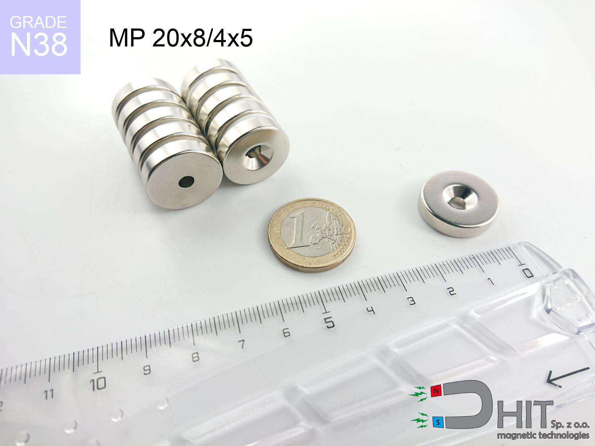
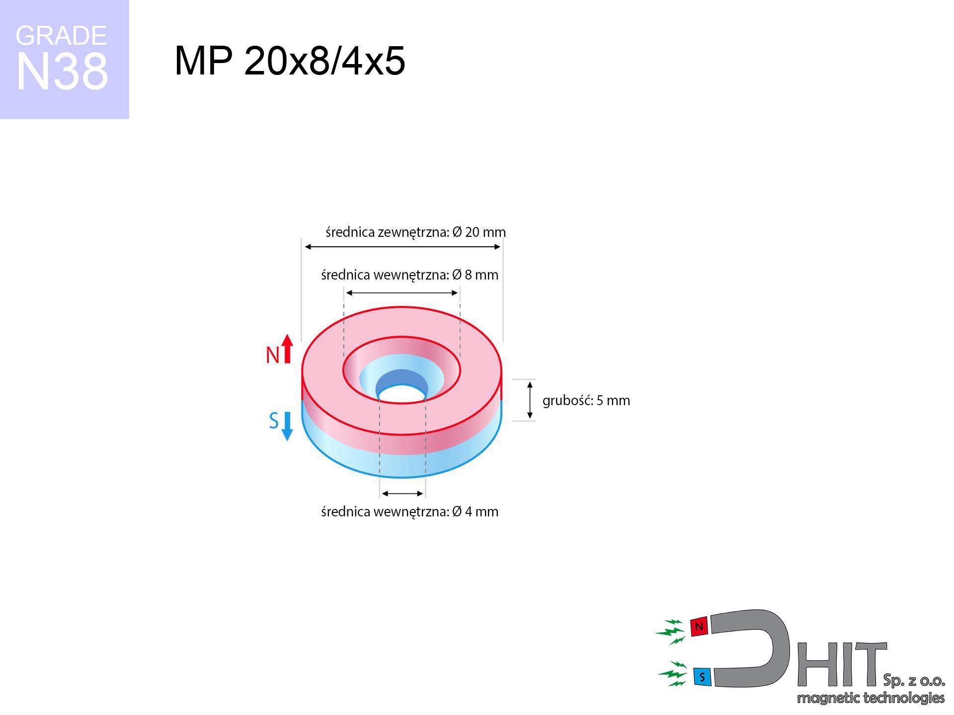
MP 20x8/4x5 / N38 - ring magnet
ring magnet
Catalog no 030333
GTIN/EAN: 5906301812272
- Diameter
- 20 mm [±0,1 mm]
- internal diameter Ø
- 8/4 mm [±0,1 mm]
- Height
- 5 mm [±0,1 mm]
- Weight
- 11.31 g
- Magnetization Direction
- ↑ axial
- Coating
- [NiCuNi] Nickel
7.75 zł with VAT / pcs + price for transport
6.30 zł net + 23% VAT / pcs
bulk discounts:
Need more?Engineering report for this magnet
Full PDF analysis: pull and shear force, effect of distance, temperature and plate thickness, safety distances and the demagnetization curve.
Give us a call
+48 888 99 98 98
alternatively get in touch through
form
the contact form page.
Parameters as well as structure of magnetic components can be reviewed using our
magnetic calculator.
Orders submitted before 14:00 will be dispatched today!
Physical properties - MP 20x8/4x5 / N38 - ring magnet
Specification / characteristics - MP 20x8/4x5 / N38 - ring magnet
| properties | values |
|---|---|
| Cat. no. | 030333 |
| GTIN/EAN | 5906301812272 |
| Production/Distribution | Dhit sp. z o.o. |
| Country of origin | Poland / China / Germany |
| Customs code | 85059029 |
| Diameter | 20 mm [±0,1 mm] |
| internal diameter Ø | 8/4 mm [±0,1 mm] |
| Height | 5 mm [±0,1 mm] |
| Weight | 11.31 g |
| Magnetization Direction | ↑ axial |
| Load capacity ~ ? | 6.65 kg / 65.21 N |
| Magnetic Induction ~ ? | 277.16 mT / 2772 Gs |
| Coating | [NiCuNi] Nickel |
| Manufacturing Tolerance | ±0.1 mm |
Magnetic properties of material N38
| properties | values | units |
|---|---|---|
| remenance Br [min. - max.] ? | 12.2-12.6 | kGs |
| remenance Br [min. - max.] ? | 1220-1260 | mT |
| coercivity bHc ? | 10.8-11.5 | kOe |
| coercivity bHc ? | 860-915 | kA/m |
| actual internal force iHc | ≥ 12 | kOe |
| actual internal force iHc | ≥ 955 | kA/m |
| energy density [min. - max.] ? | 36-38 | BH max MGOe |
| energy density [min. - max.] ? | 287-303 | BH max KJ/m |
| max. temperature ? | ≤ 80 | °C |
Physical properties of sintered neodymium magnets Nd2Fe14B at 20°C
| properties | values | units |
|---|---|---|
| Vickers hardness | ≥550 | Hv |
| Density | ≥7.4 | g/cm3 |
| Curie Temperature TC | 312 - 380 | °C |
| Curie Temperature TF | 593 - 716 | °F |
| Specific resistance | 150 | μΩ⋅cm |
| Bending strength | 250 | MPa |
| Compressive strength | 1000~1100 | MPa |
| Thermal expansion parallel (∥) to orientation (M) | (3-4) x 10-6 | °C-1 |
| Thermal expansion perpendicular (⊥) to orientation (M) | -(1-3) x 10-6 | °C-1 |
| Young's modulus | 1.7 x 10⁴ | kg/mm² |
Physical modeling of the product - technical parameters
These data represent the direct effect of a engineering calculation. Values were calculated on models for the class Nd2Fe14B. Real-world conditions might slightly differ from theoretical values. Use these data as a reference point for designers.
Table 1: Static force (pull vs gap) - interaction chart
MP 20x8/4x5 / N38
| Distance (mm) | Induction (Gauss) / mT | Pull Force (kg/lbs/g/N) | Risk Status |
|---|---|---|---|
| 0 mm |
2424 Gs
242.4 mT
|
6.65 kg / 14.66 LBS
6650.0 g / 65.2 N
|
strong |
| 1 mm |
2265 Gs
226.5 mT
|
5.81 kg / 12.80 LBS
5807.9 g / 57.0 N
|
strong |
| 2 mm |
2070 Gs
207.0 mT
|
4.85 kg / 10.69 LBS
4851.0 g / 47.6 N
|
strong |
| 3 mm |
1858 Gs
185.8 mT
|
3.91 kg / 8.61 LBS
3906.5 g / 38.3 N
|
strong |
| 5 mm |
1437 Gs
143.7 mT
|
2.34 kg / 5.16 LBS
2338.7 g / 22.9 N
|
strong |
| 10 mm |
691 Gs
69.1 mT
|
0.54 kg / 1.19 LBS
540.5 g / 5.3 N
|
weak grip |
| 15 mm |
343 Gs
34.3 mT
|
0.13 kg / 0.29 LBS
133.3 g / 1.3 N
|
weak grip |
| 20 mm |
186 Gs
18.6 mT
|
0.04 kg / 0.09 LBS
39.3 g / 0.4 N
|
weak grip |
| 30 mm |
70 Gs
7.0 mT
|
0.01 kg / 0.01 LBS
5.5 g / 0.1 N
|
weak grip |
| 50 mm |
18 Gs
1.8 mT
|
0.00 kg / 0.00 LBS
0.4 g / 0.0 N
|
weak grip |
Table 2: Vertical load (wall)
MP 20x8/4x5 / N38
| Distance (mm) | Friction coefficient | Pull Force (kg/lbs/g/N) |
|---|---|---|
| 0 mm | Stal (~0.2) |
1.33 kg / 2.93 LBS
1330.0 g / 13.0 N
|
| 1 mm | Stal (~0.2) |
1.16 kg / 2.56 LBS
1162.0 g / 11.4 N
|
| 2 mm | Stal (~0.2) |
0.97 kg / 2.14 LBS
970.0 g / 9.5 N
|
| 3 mm | Stal (~0.2) |
0.78 kg / 1.72 LBS
782.0 g / 7.7 N
|
| 5 mm | Stal (~0.2) |
0.47 kg / 1.03 LBS
468.0 g / 4.6 N
|
| 10 mm | Stal (~0.2) |
0.11 kg / 0.24 LBS
108.0 g / 1.1 N
|
| 15 mm | Stal (~0.2) |
0.03 kg / 0.06 LBS
26.0 g / 0.3 N
|
| 20 mm | Stal (~0.2) |
0.01 kg / 0.02 LBS
8.0 g / 0.1 N
|
| 30 mm | Stal (~0.2) |
0.00 kg / 0.00 LBS
2.0 g / 0.0 N
|
| 50 mm | Stal (~0.2) |
0.00 kg / 0.00 LBS
0.0 g / 0.0 N
|
Table 3: Wall mounting (shearing) - behavior on slippery surfaces
MP 20x8/4x5 / N38
| Surface type | Friction coefficient / % Mocy | Max load (kg/lbs/g/N) |
|---|---|---|
| Raw steel |
µ = 0.3
30% Nominalnej Siły
|
2.00 kg / 4.40 LBS
1995.0 g / 19.6 N
|
| Painted steel (standard) |
µ = 0.2
20% Nominalnej Siły
|
1.33 kg / 2.93 LBS
1330.0 g / 13.0 N
|
| Oily/slippery steel |
µ = 0.1
10% Nominalnej Siły
|
0.67 kg / 1.47 LBS
665.0 g / 6.5 N
|
| Magnet with anti-slip rubber |
µ = 0.5
50% Nominalnej Siły
|
3.33 kg / 7.33 LBS
3325.0 g / 32.6 N
|
Table 4: Steel thickness (substrate influence) - sheet metal selection
MP 20x8/4x5 / N38
| Steel thickness (mm) | % power | Real pull force (kg/lbs/g/N) |
|---|---|---|
| 0.5 mm |
|
0.67 kg / 1.47 LBS
665.0 g / 6.5 N
|
| 1 mm |
|
1.66 kg / 3.67 LBS
1662.5 g / 16.3 N
|
| 2 mm |
|
3.33 kg / 7.33 LBS
3325.0 g / 32.6 N
|
| 3 mm |
|
4.99 kg / 11.00 LBS
4987.5 g / 48.9 N
|
| 5 mm |
|
6.65 kg / 14.66 LBS
6650.0 g / 65.2 N
|
| 10 mm |
|
6.65 kg / 14.66 LBS
6650.0 g / 65.2 N
|
| 11 mm |
|
6.65 kg / 14.66 LBS
6650.0 g / 65.2 N
|
| 12 mm |
|
6.65 kg / 14.66 LBS
6650.0 g / 65.2 N
|
Table 5: Thermal resistance (material behavior) - resistance threshold
MP 20x8/4x5 / N38
| Ambient temp. (°C) | Power loss | Remaining pull (kg/lbs/g/N) | Status |
|---|---|---|---|
| 20 °C | 0.0% |
6.65 kg / 14.66 LBS
6650.0 g / 65.2 N
|
OK |
| 40 °C | -2.2% |
6.50 kg / 14.34 LBS
6503.7 g / 63.8 N
|
OK |
| 60 °C | -4.4% |
6.36 kg / 14.02 LBS
6357.4 g / 62.4 N
|
|
| 80 °C | -6.6% |
6.21 kg / 13.69 LBS
6211.1 g / 60.9 N
|
|
| 100 °C | -28.8% |
4.73 kg / 10.44 LBS
4734.8 g / 46.4 N
|
Table 6: Magnet-Magnet interaction (attraction) - field range
MP 20x8/4x5 / N38
| Gap (mm) | Attraction (kg/lbs) (N-S) | Shear Force (kg/lbs/g/N) | Repulsion (kg/lbs) (N-N) |
|---|---|---|---|
| 0 mm |
9.28 kg / 20.47 LBS
4 012 Gs
|
1.39 kg / 3.07 LBS
1393 g / 13.7 N
|
N/A |
| 1 mm |
8.73 kg / 19.25 LBS
4 701 Gs
|
1.31 kg / 2.89 LBS
1310 g / 12.8 N
|
7.86 kg / 17.33 LBS
~0 Gs
|
| 2 mm |
8.11 kg / 17.88 LBS
4 530 Gs
|
1.22 kg / 2.68 LBS
1216 g / 11.9 N
|
7.30 kg / 16.09 LBS
~0 Gs
|
| 3 mm |
7.45 kg / 16.42 LBS
4 342 Gs
|
1.12 kg / 2.46 LBS
1117 g / 11.0 N
|
6.70 kg / 14.78 LBS
~0 Gs
|
| 5 mm |
6.10 kg / 13.45 LBS
3 930 Gs
|
0.92 kg / 2.02 LBS
915 g / 9.0 N
|
5.49 kg / 12.11 LBS
~0 Gs
|
| 10 mm |
3.27 kg / 7.20 LBS
2 875 Gs
|
0.49 kg / 1.08 LBS
490 g / 4.8 N
|
2.94 kg / 6.48 LBS
~0 Gs
|
| 20 mm |
0.75 kg / 1.66 LBS
1 382 Gs
|
0.11 kg / 0.25 LBS
113 g / 1.1 N
|
0.68 kg / 1.50 LBS
~0 Gs
|
| 50 mm |
0.02 kg / 0.04 LBS
220 Gs
|
0.00 kg / 0.01 LBS
3 g / 0.0 N
|
0.02 kg / 0.04 LBS
~0 Gs
|
| 60 mm |
0.01 kg / 0.02 LBS
139 Gs
|
0.00 kg / 0.00 LBS
1 g / 0.0 N
|
0.00 kg / 0.00 LBS
~0 Gs
|
| 70 mm |
0.00 kg / 0.01 LBS
93 Gs
|
0.00 kg / 0.00 LBS
1 g / 0.0 N
|
0.00 kg / 0.00 LBS
~0 Gs
|
| 80 mm |
0.00 kg / 0.00 LBS
65 Gs
|
0.00 kg / 0.00 LBS
0 g / 0.0 N
|
0.00 kg / 0.00 LBS
~0 Gs
|
| 90 mm |
0.00 kg / 0.00 LBS
47 Gs
|
0.00 kg / 0.00 LBS
0 g / 0.0 N
|
0.00 kg / 0.00 LBS
~0 Gs
|
| 100 mm |
0.00 kg / 0.00 LBS
35 Gs
|
0.00 kg / 0.00 LBS
0 g / 0.0 N
|
0.00 kg / 0.00 LBS
~0 Gs
|
Table 7: Safety (HSE) (electronics) - precautionary measures
MP 20x8/4x5 / N38
| Object / Device | Limit (Gauss) / mT | Safe distance |
|---|---|---|
| Pacemaker | 5 Gs (0.5 mT) | 8.0 cm |
| Hearing aid | 10 Gs (1.0 mT) | 6.5 cm |
| Timepiece | 20 Gs (2.0 mT) | 5.0 cm |
| Mobile device | 40 Gs (4.0 mT) | 4.0 cm |
| Car key | 50 Gs (5.0 mT) | 3.5 cm |
| Payment card | 400 Gs (40.0 mT) | 1.5 cm |
| HDD hard drive | 600 Gs (60.0 mT) | 1.5 cm |
Table 8: Impact energy (cracking risk) - warning
MP 20x8/4x5 / N38
| Start from (mm) | Speed (km/h) | Energy (J) | Predicted outcome |
|---|---|---|---|
| 10 mm |
25.22 km/h
(7.01 m/s)
|
0.28 J | |
| 30 mm |
26.09 km/h
(7.25 m/s)
|
0.30 J | |
| 50 mm |
26.10 km/h
(7.25 m/s)
|
0.30 J | |
| 100 mm |
26.11 km/h
(7.25 m/s)
|
0.30 J |
Table 9: Corrosion resistance
MP 20x8/4x5 / N38
| Technical parameter | Value / Description |
|---|---|
| Coating type | [NiCuNi] Nickel |
| Layer structure | Nickel - Copper - Nickel |
| Layer thickness | 10-20 µm |
| Salt spray test (SST) ? | 24 h |
| Recommended environment | Indoors only (dry) |
Table 10: Electrical data (Pc)
MP 20x8/4x5 / N38
| Parameter | Value | SI Unit / Description |
|---|---|---|
| Magnetic Flux | 7 218 Mx | 72.2 µWb |
| Pc Coefficient | 0.31 | Low (Flat) |
Table 11: Submerged application
MP 20x8/4x5 / N38
| Environment | Effective steel pull | Effect |
|---|---|---|
| Air (land) | 6.65 kg | Standard |
| Water (riverbed) |
7.61 kg
(+0.96 kg buoyancy gain)
|
+14.5% |
1. Vertical hold
*Note: On a vertical surface, the magnet holds just approx. 20-30% of its nominal pull.
2. Steel thickness impact
*Thin metal sheet (e.g. computer case) significantly limits the holding force.
3. Heat tolerance
*For N38 grade, the max working temp is 80°C.
4. Demagnetization curve and operating point (B-H)
chart generated for the permeance coefficient Pc (Permeance Coefficient) = 0.31
The chart above illustrates the magnetic characteristics of the material within the second quadrant of the hysteresis loop. The solid red line represents the demagnetization curve (material potential), while the dashed blue line is the load line based on the magnet's geometry. The Pc (Permeance Coefficient), also known as the load line slope, is a dimensionless value that describes the relationship between the magnet's shape and its magnetic stability. The intersection of these two lines (the black dot) is the operating point — it determines the actual magnetic flux density generated by the magnet in this specific configuration. A higher Pc value means the magnet is more 'slender' (tall relative to its area), resulting in a higher operating point and better resistance to irreversible demagnetization caused by external fields or temperature. A value of 0.42 is relatively low (typical for flat magnets), meaning the operating point is closer to the 'knee' of the curve — caution is advised when operating at temperatures near the maximum limit to avoid strength loss.
Elemental analysis
| iron (Fe) | 64% – 68% |
| neodymium (Nd) | 29% – 32% |
| boron (B) | 1.1% – 1.2% |
| dysprosium (Dy) | 0.5% – 2.0% |
| coating (Ni-Cu-Ni) | < 0.05% |
Ecology and recycling (GPSR)
| recyclability (EoL) | 100% |
| recycled raw materials | ~10% (pre-cons) |
| carbon footprint | low / zredukowany |
| waste code (EWC) | 16 02 16 |
See also products

![UMP 97x40 [M8+M10] GW F300 kg / N38 - search holder](https://cdn3.dhit.pl/graphics/products/ump97x40-m8+m10-gw-f-300-kg-kic.jpg "UMP 97x40 [M8+M10] GW F300 kg / N38 - search holder")

![SM 25x275 [2xM8] / N42 - magnetic separator](https://cdn3.dhit.pl/graphics/products/sm-25x275-2xm8-boc.jpg "SM 25x275 [2xM8] / N42 - magnetic separator")
Advantages and disadvantages of neodymium magnets.
Benefits
- They have stable power, and over around 10 years their performance decreases symbolically – ~1% (according to theory),
- They retain their magnetic properties even under close interference source,
- Thanks to the metallic finish, the surface of nickel, gold, or silver gives an professional appearance,
- Neodymium magnets achieve maximum magnetic induction on a small surface, which ensures high operational effectiveness,
- Made from properly selected components, these magnets show impressive resistance to high heat, enabling them to function (depending on their form) at temperatures up to 230°C and above...
- In view of the possibility of accurate shaping and customization to specialized needs, NdFeB magnets can be manufactured in a broad palette of shapes and sizes, which expands the range of possible applications,
- Wide application in innovative solutions – they find application in hard drives, motor assemblies, diagnostic systems, also multitasking production systems.
- Compactness – despite small sizes they offer powerful magnetic field, making them ideal for precision applications
Weaknesses
- At very strong impacts they can break, therefore we recommend placing them in special holders. A metal housing provides additional protection against damage and increases the magnet's durability.
- Neodymium magnets decrease their strength under the influence of heating. As soon as 80°C is exceeded, many of them start losing their force. Therefore, we recommend our special magnets marked [AH], which maintain stability even at temperatures up to 230°C
- When exposed to humidity, magnets usually rust. To use them in conditions outside, it is recommended to use protective magnets, such as magnets in rubber or plastics, which secure oxidation and corrosion.
- Due to limitations in realizing threads and complicated forms in magnets, we propose using a housing - magnetic mechanism.
- Potential hazard to health – tiny shards of magnets can be dangerous, in case of ingestion, which becomes key in the context of child health protection. It is also worth noting that tiny parts of these devices are able to be problematic in diagnostics medical when they are in the body.
- With budget limitations the cost of neodymium magnets can be a barrier,
Pull force analysis
Magnetic strength at its maximum – what contributes to it?
- using a plate made of low-carbon steel, functioning as a circuit closing element
- with a cross-section no less than 10 mm
- with a plane cleaned and smooth
- without the slightest clearance between the magnet and steel
- for force acting at a right angle (in the magnet axis)
- at conditions approx. 20°C
Impact of factors on magnetic holding capacity in practice
- Distance – the presence of foreign body (paint, dirt, air) acts as an insulator, which lowers capacity steeply (even by 50% at 0.5 mm).
- Angle of force application – highest force is available only during pulling at a 90° angle. The shear force of the magnet along the surface is usually many times lower (approx. 1/5 of the lifting capacity).
- Element thickness – to utilize 100% power, the steel must be sufficiently thick. Paper-thin metal limits the attraction force (the magnet "punches through" it).
- Material composition – not every steel reacts the same. Alloy additives worsen the interaction with the magnet.
- Plate texture – ground elements guarantee perfect abutment, which increases force. Uneven metal reduce efficiency.
- Heat – neodymium magnets have a sensitivity to temperature. At higher temperatures they are weaker, and in frost gain strength (up to a certain limit).
Lifting capacity testing was conducted on plates with a smooth surface of suitable thickness, under perpendicular forces, in contrast under attempts to slide the magnet the load capacity is reduced by as much as fivefold. In addition, even a slight gap between the magnet and the plate reduces the holding force.
Safety rules for work with NdFeB magnets
Do not give to children
Absolutely keep magnets out of reach of children. Ingestion danger is high, and the effects of magnets clamping inside the body are very dangerous.
Compass and GPS
Navigation devices and smartphones are extremely sensitive to magnetism. Close proximity with a powerful NdFeB magnet can ruin the sensors in your phone.
Shattering risk
Protect your eyes. Magnets can explode upon uncontrolled impact, ejecting sharp fragments into the air. Wear goggles.
Bodily injuries
Danger of trauma: The attraction force is so immense that it can cause blood blisters, crushing, and even bone fractures. Protective gloves are recommended.
Health Danger
Life threat: Strong magnets can turn off pacemakers and defibrillators. Do not approach if you have medical devices.
Combustion hazard
Mechanical processing of neodymium magnets poses a fire risk. Magnetic powder reacts violently with oxygen and is hard to extinguish.
Conscious usage
Handle magnets with awareness. Their immense force can shock even experienced users. Stay alert and do not underestimate their force.
Avoid contact if allergic
Some people experience a hypersensitivity to nickel, which is the common plating for NdFeB magnets. Frequent touching might lead to a rash. We suggest wear safety gloves.
Electronic hazard
Equipment safety: Strong magnets can ruin data carriers and delicate electronics (pacemakers, medical aids, timepieces).
Permanent damage
Avoid heat. Neodymium magnets are sensitive to heat. If you require resistance above 80°C, look for HT versions (H, SH, UH).
Tabela kosztu i czasu dostawy
Płatność przed wysyłką:

GLS kurier
Przesyłka będzie u Ciebie za 2-3 dni
14.99 ZŁ

InPost Paczkomaty 24/7
Przesyłka będzie u Ciebie za 1-2 dni
12.30 ZŁ
Płatność przy odbiorze (pobranie):
GLS kurier
Przesyłka będzie u Ciebie za 1-2 dni
23.00 ZŁ
Rate the product
Your rating