
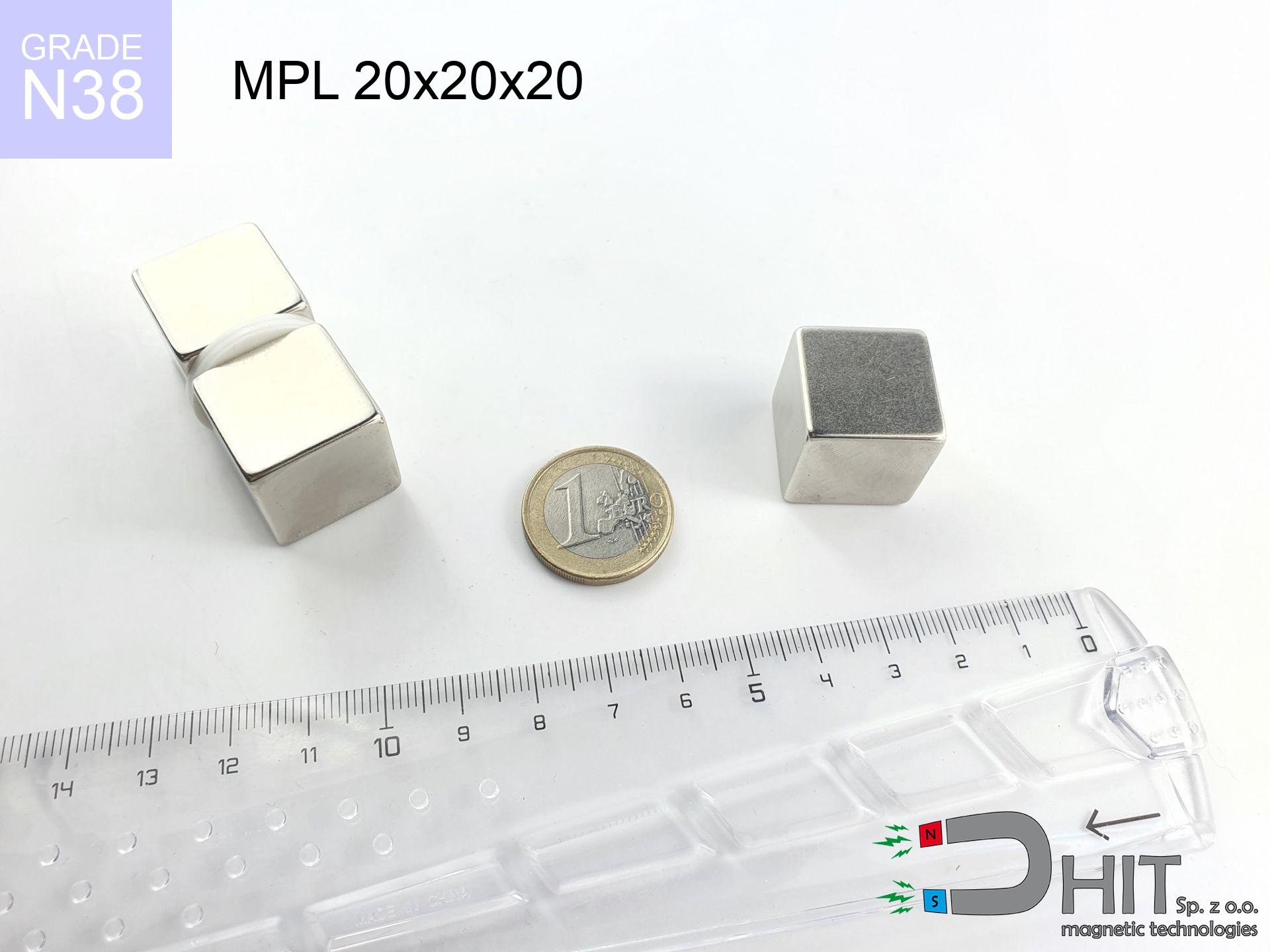
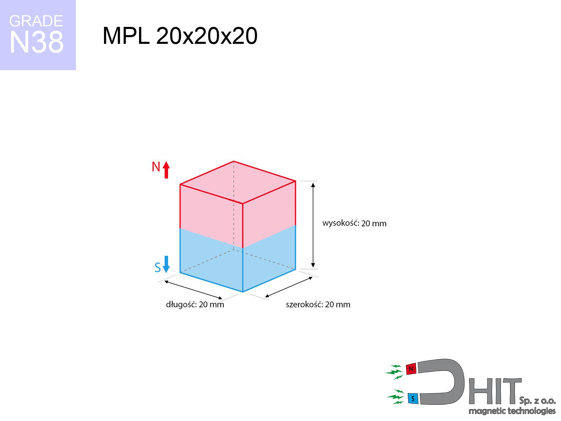
MPL 20x20x20 / N38 - lamellar magnet
lamellar magnet
Catalog no 020129
GTIN/EAN: 5906301811350
length
20 mm [±0,1 mm]
Width
20 mm [±0,1 mm]
Height
20 mm [±0,1 mm]
Weight
60 g
Magnetization Direction
↑ axial
Load capacity
15.40 kg / 151.12 N
Magnetic Induction
540.22 mT / 5402 Gs
Coating
[NiCuNi] Nickel
33.21 ZŁ with VAT / pcs + price for transport
27.00 ZŁ net + 23% VAT / pcs
bulk discounts:
Need more?
Call us now
+48 888 99 98 98
or let us know by means of
form
the contact section.
Specifications and appearance of magnets can be reviewed using our
our magnetic calculator.
Orders placed before 14:00 will be shipped the same business day.
Technical data - MPL 20x20x20 / N38 - lamellar magnet
Specification / characteristics - MPL 20x20x20 / N38 - lamellar magnet
| properties | values |
|---|---|
| Cat. no. | 020129 |
| GTIN/EAN | 5906301811350 |
| Production/Distribution | Dhit sp. z o.o. |
| Country of origin | Poland / China / Germany |
| Customs code | 85059029 |
| length | 20 mm [±0,1 mm] |
| Width | 20 mm [±0,1 mm] |
| Height | 20 mm [±0,1 mm] |
| Weight | 60 g |
| Magnetization Direction | ↑ axial |
| Load capacity ~ ? | 15.40 kg / 151.12 N |
| Magnetic Induction ~ ? | 540.22 mT / 5402 Gs |
| Coating | [NiCuNi] Nickel |
| Manufacturing Tolerance | ±0.1 mm |
Magnetic properties of material N38
| properties | values | units |
|---|---|---|
| remenance Br [min. - max.] ? | 12.2-12.6 | kGs |
| remenance Br [min. - max.] ? | 1220-1260 | mT |
| coercivity bHc ? | 10.8-11.5 | kOe |
| coercivity bHc ? | 860-915 | kA/m |
| actual internal force iHc | ≥ 12 | kOe |
| actual internal force iHc | ≥ 955 | kA/m |
| energy density [min. - max.] ? | 36-38 | BH max MGOe |
| energy density [min. - max.] ? | 287-303 | BH max KJ/m |
| max. temperature ? | ≤ 80 | °C |
Physical properties of sintered neodymium magnets Nd2Fe14B at 20°C
| properties | values | units |
|---|---|---|
| Vickers hardness | ≥550 | Hv |
| Density | ≥7.4 | g/cm3 |
| Curie Temperature TC | 312 - 380 | °C |
| Curie Temperature TF | 593 - 716 | °F |
| Specific resistance | 150 | μΩ⋅cm |
| Bending strength | 250 | MPa |
| Compressive strength | 1000~1100 | MPa |
| Thermal expansion parallel (∥) to orientation (M) | (3-4) x 10-6 | °C-1 |
| Thermal expansion perpendicular (⊥) to orientation (M) | -(1-3) x 10-6 | °C-1 |
| Young's modulus | 1.7 x 10⁴ | kg/mm² |
Technical analysis of the magnet - technical parameters
These data are the result of a mathematical analysis. Results are based on models for the material Nd2Fe14B. Real-world conditions might slightly differ. Please consider these calculations as a reference point when designing systems.
Table 1: Static force (pull vs distance) - power drop
MPL 20x20x20 / N38
| Distance (mm) | Induction (Gauss) / mT | Pull Force (kg/lbs/g/N) | Risk Status |
|---|---|---|---|
| 0 mm |
5400 Gs
540.0 mT
|
15.40 kg / 33.95 LBS
15400.0 g / 151.1 N
|
dangerous! |
| 1 mm |
4910 Gs
491.0 mT
|
12.73 kg / 28.07 LBS
12732.2 g / 124.9 N
|
dangerous! |
| 2 mm |
4423 Gs
442.3 mT
|
10.33 kg / 22.77 LBS
10328.3 g / 101.3 N
|
dangerous! |
| 3 mm |
3955 Gs
395.5 mT
|
8.26 kg / 18.21 LBS
8258.3 g / 81.0 N
|
strong |
| 5 mm |
3114 Gs
311.4 mT
|
5.12 kg / 11.29 LBS
5120.3 g / 50.2 N
|
strong |
| 10 mm |
1671 Gs
167.1 mT
|
1.48 kg / 3.25 LBS
1475.0 g / 14.5 N
|
low risk |
| 15 mm |
936 Gs
93.6 mT
|
0.46 kg / 1.02 LBS
463.0 g / 4.5 N
|
low risk |
| 20 mm |
562 Gs
56.2 mT
|
0.17 kg / 0.37 LBS
167.1 g / 1.6 N
|
low risk |
| 30 mm |
244 Gs
24.4 mT
|
0.03 kg / 0.07 LBS
31.3 g / 0.3 N
|
low risk |
| 50 mm |
73 Gs
7.3 mT
|
0.00 kg / 0.01 LBS
2.8 g / 0.0 N
|
low risk |
Table 2: Sliding capacity (vertical surface)
MPL 20x20x20 / N38
| Distance (mm) | Friction coefficient | Pull Force (kg/lbs/g/N) |
|---|---|---|
| 0 mm | Stal (~0.2) |
3.08 kg / 6.79 LBS
3080.0 g / 30.2 N
|
| 1 mm | Stal (~0.2) |
2.55 kg / 5.61 LBS
2546.0 g / 25.0 N
|
| 2 mm | Stal (~0.2) |
2.07 kg / 4.55 LBS
2066.0 g / 20.3 N
|
| 3 mm | Stal (~0.2) |
1.65 kg / 3.64 LBS
1652.0 g / 16.2 N
|
| 5 mm | Stal (~0.2) |
1.02 kg / 2.26 LBS
1024.0 g / 10.0 N
|
| 10 mm | Stal (~0.2) |
0.30 kg / 0.65 LBS
296.0 g / 2.9 N
|
| 15 mm | Stal (~0.2) |
0.09 kg / 0.20 LBS
92.0 g / 0.9 N
|
| 20 mm | Stal (~0.2) |
0.03 kg / 0.07 LBS
34.0 g / 0.3 N
|
| 30 mm | Stal (~0.2) |
0.01 kg / 0.01 LBS
6.0 g / 0.1 N
|
| 50 mm | Stal (~0.2) |
0.00 kg / 0.00 LBS
0.0 g / 0.0 N
|
Table 3: Vertical assembly (shearing) - vertical pull
MPL 20x20x20 / N38
| Surface type | Friction coefficient / % Mocy | Max load (kg/lbs/g/N) |
|---|---|---|
| Raw steel |
µ = 0.3
30% Nominalnej Siły
|
4.62 kg / 10.19 LBS
4620.0 g / 45.3 N
|
| Painted steel (standard) |
µ = 0.2
20% Nominalnej Siły
|
3.08 kg / 6.79 LBS
3080.0 g / 30.2 N
|
| Oily/slippery steel |
µ = 0.1
10% Nominalnej Siły
|
1.54 kg / 3.40 LBS
1540.0 g / 15.1 N
|
| Magnet with anti-slip rubber |
µ = 0.5
50% Nominalnej Siły
|
7.70 kg / 16.98 LBS
7700.0 g / 75.5 N
|
Table 4: Material efficiency (saturation) - power losses
MPL 20x20x20 / N38
| Steel thickness (mm) | % power | Real pull force (kg/lbs/g/N) |
|---|---|---|
| 0.5 mm |
|
0.77 kg / 1.70 LBS
770.0 g / 7.6 N
|
| 1 mm |
|
1.93 kg / 4.24 LBS
1925.0 g / 18.9 N
|
| 2 mm |
|
3.85 kg / 8.49 LBS
3850.0 g / 37.8 N
|
| 3 mm |
|
5.78 kg / 12.73 LBS
5775.0 g / 56.7 N
|
| 5 mm |
|
9.63 kg / 21.22 LBS
9625.0 g / 94.4 N
|
| 10 mm |
|
15.40 kg / 33.95 LBS
15400.0 g / 151.1 N
|
| 11 mm |
|
15.40 kg / 33.95 LBS
15400.0 g / 151.1 N
|
| 12 mm |
|
15.40 kg / 33.95 LBS
15400.0 g / 151.1 N
|
Table 5: Working in heat (stability) - resistance threshold
MPL 20x20x20 / N38
| Ambient temp. (°C) | Power loss | Remaining pull (kg/lbs/g/N) | Status |
|---|---|---|---|
| 20 °C | 0.0% |
15.40 kg / 33.95 LBS
15400.0 g / 151.1 N
|
OK |
| 40 °C | -2.2% |
15.06 kg / 33.20 LBS
15061.2 g / 147.8 N
|
OK |
| 60 °C | -4.4% |
14.72 kg / 32.46 LBS
14722.4 g / 144.4 N
|
OK |
| 80 °C | -6.6% |
14.38 kg / 31.71 LBS
14383.6 g / 141.1 N
|
|
| 100 °C | -28.8% |
10.96 kg / 24.17 LBS
10964.8 g / 107.6 N
|
Table 6: Two magnets (attraction) - field collision
MPL 20x20x20 / N38
| Gap (mm) | Attraction (kg/lbs) (N-S) | Shear Strength (kg/lbs/g/N) | Repulsion (kg/lbs) (N-N) |
|---|---|---|---|
| 0 mm |
71.92 kg / 158.55 LBS
5 962 Gs
|
10.79 kg / 23.78 LBS
10787 g / 105.8 N
|
N/A |
| 1 mm |
65.60 kg / 144.63 LBS
10 316 Gs
|
9.84 kg / 21.69 LBS
9840 g / 96.5 N
|
59.04 kg / 130.16 LBS
~0 Gs
|
| 2 mm |
59.46 kg / 131.08 LBS
9 821 Gs
|
8.92 kg / 19.66 LBS
8919 g / 87.5 N
|
53.51 kg / 117.97 LBS
~0 Gs
|
| 3 mm |
53.66 kg / 118.30 LBS
9 329 Gs
|
8.05 kg / 17.74 LBS
8049 g / 79.0 N
|
48.29 kg / 106.47 LBS
~0 Gs
|
| 5 mm |
43.20 kg / 95.24 LBS
8 371 Gs
|
6.48 kg / 14.29 LBS
6480 g / 63.6 N
|
38.88 kg / 85.71 LBS
~0 Gs
|
| 10 mm |
23.91 kg / 52.72 LBS
6 228 Gs
|
3.59 kg / 7.91 LBS
3587 g / 35.2 N
|
21.52 kg / 47.44 LBS
~0 Gs
|
| 20 mm |
6.89 kg / 15.19 LBS
3 343 Gs
|
1.03 kg / 2.28 LBS
1033 g / 10.1 N
|
6.20 kg / 13.67 LBS
~0 Gs
|
| 50 mm |
0.32 kg / 0.71 LBS
721 Gs
|
0.05 kg / 0.11 LBS
48 g / 0.5 N
|
0.29 kg / 0.64 LBS
~0 Gs
|
| 60 mm |
0.15 kg / 0.32 LBS
487 Gs
|
0.02 kg / 0.05 LBS
22 g / 0.2 N
|
0.13 kg / 0.29 LBS
~0 Gs
|
| 70 mm |
0.07 kg / 0.16 LBS
344 Gs
|
0.01 kg / 0.02 LBS
11 g / 0.1 N
|
0.07 kg / 0.14 LBS
~0 Gs
|
| 80 mm |
0.04 kg / 0.09 LBS
251 Gs
|
0.01 kg / 0.01 LBS
6 g / 0.1 N
|
0.04 kg / 0.08 LBS
~0 Gs
|
| 90 mm |
0.02 kg / 0.05 LBS
189 Gs
|
0.00 kg / 0.01 LBS
3 g / 0.0 N
|
0.02 kg / 0.04 LBS
~0 Gs
|
| 100 mm |
0.01 kg / 0.03 LBS
146 Gs
|
0.00 kg / 0.00 LBS
2 g / 0.0 N
|
0.01 kg / 0.03 LBS
~0 Gs
|
Table 7: Protective zones (implants) - precautionary measures
MPL 20x20x20 / N38
| Object / Device | Limit (Gauss) / mT | Safe distance |
|---|---|---|
| Pacemaker | 5 Gs (0.5 mT) | 14.0 cm |
| Hearing aid | 10 Gs (1.0 mT) | 11.0 cm |
| Mechanical watch | 20 Gs (2.0 mT) | 8.5 cm |
| Phone / Smartphone | 40 Gs (4.0 mT) | 6.5 cm |
| Car key | 50 Gs (5.0 mT) | 6.0 cm |
| Payment card | 400 Gs (40.0 mT) | 2.5 cm |
| HDD hard drive | 600 Gs (60.0 mT) | 2.0 cm |
Table 8: Dynamics (kinetic energy) - warning
MPL 20x20x20 / N38
| Start from (mm) | Speed (km/h) | Energy (J) | Predicted outcome |
|---|---|---|---|
| 10 mm |
17.10 km/h
(4.75 m/s)
|
0.68 J | |
| 30 mm |
28.02 km/h
(7.78 m/s)
|
1.82 J | |
| 50 mm |
36.13 km/h
(10.04 m/s)
|
3.02 J | |
| 100 mm |
51.09 km/h
(14.19 m/s)
|
6.04 J |
Table 9: Corrosion resistance
MPL 20x20x20 / N38
| Technical parameter | Value / Description |
|---|---|
| Coating type | [NiCuNi] Nickel |
| Layer structure | Nickel - Copper - Nickel |
| Layer thickness | 10-20 µm |
| Salt spray test (SST) ? | 24 h |
| Recommended environment | Indoors only (dry) |
Table 10: Construction data (Pc)
MPL 20x20x20 / N38
| Parameter | Value | SI Unit / Description |
|---|---|---|
| Magnetic Flux | 22 017 Mx | 220.2 µWb |
| Pc Coefficient | 0.84 | High (Stable) |
Table 11: Physics of underwater searching
MPL 20x20x20 / N38
| Environment | Effective steel pull | Effect |
|---|---|---|
| Air (land) | 15.40 kg | Standard |
| Water (riverbed) |
17.63 kg
(+2.23 kg buoyancy gain)
|
+14.5% |
1. Vertical hold
*Note: On a vertical surface, the magnet holds just a fraction of its perpendicular strength.
2. Efficiency vs thickness
*Thin metal sheet (e.g. computer case) significantly limits the holding force.
3. Temperature resistance
*For N38 material, the critical limit is 80°C.
4. Demagnetization curve and operating point (B-H)
chart generated for the permeance coefficient Pc (Permeance Coefficient) = 0.84
The chart above illustrates the magnetic characteristics of the material within the second quadrant of the hysteresis loop. The solid red line represents the demagnetization curve (material potential), while the dashed blue line is the load line based on the magnet's geometry. The Pc (Permeance Coefficient), also known as the load line slope, is a dimensionless value that describes the relationship between the magnet's shape and its magnetic stability. The intersection of these two lines (the black dot) is the operating point — it determines the actual magnetic flux density generated by the magnet in this specific configuration. A higher Pc value means the magnet is more 'slender' (tall relative to its area), resulting in a higher operating point and better resistance to irreversible demagnetization caused by external fields or temperature. A value of 0.42 is relatively low (typical for flat magnets), meaning the operating point is closer to the 'knee' of the curve — caution is advised when operating at temperatures near the maximum limit to avoid strength loss.
Material specification
| iron (Fe) | 64% – 68% |
| neodymium (Nd) | 29% – 32% |
| boron (B) | 1.1% – 1.2% |
| dysprosium (Dy) | 0.5% – 2.0% |
| coating (Ni-Cu-Ni) | < 0.05% |
Environmental data
| recyclability (EoL) | 100% |
| recycled raw materials | ~10% (pre-cons) |
| carbon footprint | low / zredukowany |
| waste code (EWC) | 16 02 16 |
See also offers
![BM 700x180x75 [8xM10] - magnetic beam](https://cdn3.dhit.pl/graphics/blank.jpg "BM 700x180x75 [8xM10] - magnetic beam")

![UMGZ 16x13x5 [M4] GZ / N38 - magnetic holder external thread](https://cdn3.dhit.pl/graphics/products/um-16x13x5-m4-gz-cor.jpg "UMGZ 16x13x5 [M4] GZ / N38 - magnetic holder external thread")

Strengths and weaknesses of rare earth magnets.
Pros
- They virtually do not lose power, because even after 10 years the performance loss is only ~1% (according to literature),
- Magnets very well defend themselves against demagnetization caused by external fields,
- The use of an metallic coating of noble metals (nickel, gold, silver) causes the element to have aesthetics,
- Magnetic induction on the working part of the magnet turns out to be exceptional,
- Thanks to resistance to high temperature, they are able to function (depending on the form) even at temperatures up to 230°C and higher...
- Possibility of exact machining and optimizing to complex conditions,
- Key role in electronics industry – they find application in data components, motor assemblies, precision medical tools, as well as industrial machines.
- Relatively small size with high pulling force – neodymium magnets offer strong magnetic field in small dimensions, which makes them useful in miniature devices
Weaknesses
- Brittleness is one of their disadvantages. Upon intense impact they can break. We advise keeping them in a special holder, which not only protects them against impacts but also raises their durability
- NdFeB magnets lose strength when exposed to high temperatures. After reaching 80°C, many of them experience permanent weakening of strength (a factor is the shape and dimensions of the magnet). We offer magnets specially adapted to work at temperatures up to 230°C marked [AH], which are very resistant to heat
- They rust in a humid environment. For use outdoors we suggest using waterproof magnets e.g. in rubber, plastic
- We recommend cover - magnetic holder, due to difficulties in producing nuts inside the magnet and complicated shapes.
- Health risk related to microscopic parts of magnets can be dangerous, if swallowed, which is particularly important in the context of child health protection. Furthermore, small elements of these magnets can be problematic in diagnostics medical when they are in the body.
- Higher cost of purchase is one of the disadvantages compared to ceramic magnets, especially in budget applications
Pull force analysis
Magnetic strength at its maximum – what contributes to it?
- with the use of a yoke made of special test steel, ensuring full magnetic saturation
- with a cross-section minimum 10 mm
- with a plane perfectly flat
- with total lack of distance (without paint)
- during pulling in a direction vertical to the mounting surface
- at conditions approx. 20°C
Practical lifting capacity: influencing factors
- Space between surfaces – even a fraction of a millimeter of separation (caused e.g. by varnish or dirt) diminishes the magnet efficiency, often by half at just 0.5 mm.
- Pull-off angle – note that the magnet holds strongest perpendicularly. Under shear forces, the capacity drops significantly, often to levels of 20-30% of the maximum value.
- Steel thickness – insufficiently thick plate causes magnetic saturation, causing part of the power to be escaped to the other side.
- Material type – the best choice is pure iron steel. Hardened steels may generate lower lifting capacity.
- Smoothness – full contact is obtained only on smooth steel. Any scratches and bumps reduce the real contact area, weakening the magnet.
- Temperature influence – high temperature weakens pulling force. Exceeding the limit temperature can permanently demagnetize the magnet.
Lifting capacity testing was carried out on plates with a smooth surface of optimal thickness, under perpendicular forces, however under attempts to slide the magnet the load capacity is reduced by as much as fivefold. In addition, even a slight gap between the magnet and the plate reduces the holding force.
Precautions when working with neodymium magnets
Demagnetization risk
Regular neodymium magnets (N-type) lose magnetization when the temperature goes above 80°C. Damage is permanent.
Medical interference
Warning for patients: Strong magnetic fields disrupt medical devices. Keep minimum 30 cm distance or request help to handle the magnets.
Protective goggles
Despite metallic appearance, neodymium is delicate and not impact-resistant. Do not hit, as the magnet may crumble into sharp, dangerous pieces.
Swallowing risk
Only for adults. Tiny parts pose a choking risk, leading to intestinal necrosis. Keep away from kids and pets.
Skin irritation risks
A percentage of the population suffer from a contact allergy to nickel, which is the standard coating for NdFeB magnets. Frequent touching may cause a rash. It is best to wear safety gloves.
Handling guide
Handle with care. Rare earth magnets attract from a distance and connect with massive power, often faster than you can react.
Protect data
Do not bring magnets close to a wallet, computer, or screen. The magnetism can irreversibly ruin these devices and erase data from cards.
Dust is flammable
Fire warning: Rare earth powder is highly flammable. Avoid machining magnets without safety gear as this risks ignition.
Precision electronics
Navigation devices and mobile phones are highly susceptible to magnetism. Direct contact with a strong magnet can decalibrate the internal compass in your phone.
Pinching danger
Large magnets can crush fingers in a fraction of a second. Never place your hand between two attracting surfaces.
Tabela kosztu i czasu dostawy
Płatność przed wysyłką:

GLS kurier
Przesyłka będzie u Ciebie za 2-3 dni
14.99 ZŁ

InPost Paczkomaty 24/7
Przesyłka będzie u Ciebie za 1-2 dni
12.30 ZŁ
Płatność przy odbiorze (pobranie):
GLS kurier
Przesyłka będzie u Ciebie za 1-2 dni
23.00 ZŁ
Rate the product
Your rating