
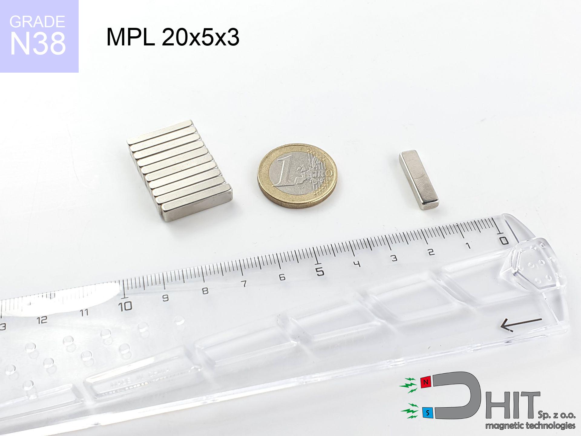
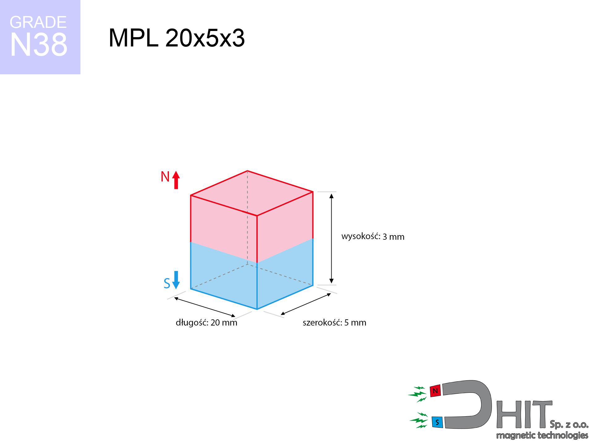
MPL 20x5x3 / N38 - lamellar magnet
lamellar magnet
Catalog no 020131
GTIN/EAN: 5906301811374
length
20 mm [±0,1 mm]
Width
5 mm [±0,1 mm]
Height
3 mm [±0,1 mm]
Weight
2.25 g
Magnetization Direction
↑ axial
Load capacity
3.46 kg / 33.93 N
Magnetic Induction
358.88 mT / 3589 Gs
Coating
[NiCuNi] Nickel
1.058 ZŁ with VAT / pcs + price for transport
0.860 ZŁ net + 23% VAT / pcs
bulk discounts:
Need more?
Call us
+48 22 499 98 98
alternatively let us know by means of
contact form
the contact page.
Strength and appearance of magnets can be verified on our
magnetic mass calculator.
Same-day shipping for orders placed before 14:00.
Technical data - MPL 20x5x3 / N38 - lamellar magnet
Specification / characteristics - MPL 20x5x3 / N38 - lamellar magnet
| properties | values |
|---|---|
| Cat. no. | 020131 |
| GTIN/EAN | 5906301811374 |
| Production/Distribution | Dhit sp. z o.o. |
| Country of origin | Poland / China / Germany |
| Customs code | 85059029 |
| length | 20 mm [±0,1 mm] |
| Width | 5 mm [±0,1 mm] |
| Height | 3 mm [±0,1 mm] |
| Weight | 2.25 g |
| Magnetization Direction | ↑ axial |
| Load capacity ~ ? | 3.46 kg / 33.93 N |
| Magnetic Induction ~ ? | 358.88 mT / 3589 Gs |
| Coating | [NiCuNi] Nickel |
| Manufacturing Tolerance | ±0.1 mm |
Magnetic properties of material N38
| properties | values | units |
|---|---|---|
| remenance Br [min. - max.] ? | 12.2-12.6 | kGs |
| remenance Br [min. - max.] ? | 1220-1260 | mT |
| coercivity bHc ? | 10.8-11.5 | kOe |
| coercivity bHc ? | 860-915 | kA/m |
| actual internal force iHc | ≥ 12 | kOe |
| actual internal force iHc | ≥ 955 | kA/m |
| energy density [min. - max.] ? | 36-38 | BH max MGOe |
| energy density [min. - max.] ? | 287-303 | BH max KJ/m |
| max. temperature ? | ≤ 80 | °C |
Physical properties of sintered neodymium magnets Nd2Fe14B at 20°C
| properties | values | units |
|---|---|---|
| Vickers hardness | ≥550 | Hv |
| Density | ≥7.4 | g/cm3 |
| Curie Temperature TC | 312 - 380 | °C |
| Curie Temperature TF | 593 - 716 | °F |
| Specific resistance | 150 | μΩ⋅cm |
| Bending strength | 250 | MPa |
| Compressive strength | 1000~1100 | MPa |
| Thermal expansion parallel (∥) to orientation (M) | (3-4) x 10-6 | °C-1 |
| Thermal expansion perpendicular (⊥) to orientation (M) | -(1-3) x 10-6 | °C-1 |
| Young's modulus | 1.7 x 10⁴ | kg/mm² |
Technical analysis of the product - report
The following data are the outcome of a physical analysis. Values are based on algorithms for the material Nd2Fe14B. Real-world parameters may differ from theoretical values. Please consider these calculations as a supplementary guide for designers.
Table 1: Static force (pull vs gap) - characteristics
MPL 20x5x3 / N38
| Distance (mm) | Induction (Gauss) / mT | Pull Force (kg/lbs/g/N) | Risk Status |
|---|---|---|---|
| 0 mm |
3585 Gs
358.5 mT
|
3.46 kg / 7.63 LBS
3460.0 g / 33.9 N
|
warning |
| 1 mm |
2619 Gs
261.9 mT
|
1.85 kg / 4.07 LBS
1846.6 g / 18.1 N
|
safe |
| 2 mm |
1818 Gs
181.8 mT
|
0.89 kg / 1.96 LBS
889.8 g / 8.7 N
|
safe |
| 3 mm |
1279 Gs
127.9 mT
|
0.44 kg / 0.97 LBS
440.2 g / 4.3 N
|
safe |
| 5 mm |
696 Gs
69.6 mT
|
0.13 kg / 0.29 LBS
130.6 g / 1.3 N
|
safe |
| 10 mm |
225 Gs
22.5 mT
|
0.01 kg / 0.03 LBS
13.6 g / 0.1 N
|
safe |
| 15 mm |
97 Gs
9.7 mT
|
0.00 kg / 0.01 LBS
2.5 g / 0.0 N
|
safe |
| 20 mm |
49 Gs
4.9 mT
|
0.00 kg / 0.00 LBS
0.6 g / 0.0 N
|
safe |
| 30 mm |
17 Gs
1.7 mT
|
0.00 kg / 0.00 LBS
0.1 g / 0.0 N
|
safe |
| 50 mm |
4 Gs
0.4 mT
|
0.00 kg / 0.00 LBS
0.0 g / 0.0 N
|
safe |
Table 2: Shear capacity (vertical surface)
MPL 20x5x3 / N38
| Distance (mm) | Friction coefficient | Pull Force (kg/lbs/g/N) |
|---|---|---|
| 0 mm | Stal (~0.2) |
0.69 kg / 1.53 LBS
692.0 g / 6.8 N
|
| 1 mm | Stal (~0.2) |
0.37 kg / 0.82 LBS
370.0 g / 3.6 N
|
| 2 mm | Stal (~0.2) |
0.18 kg / 0.39 LBS
178.0 g / 1.7 N
|
| 3 mm | Stal (~0.2) |
0.09 kg / 0.19 LBS
88.0 g / 0.9 N
|
| 5 mm | Stal (~0.2) |
0.03 kg / 0.06 LBS
26.0 g / 0.3 N
|
| 10 mm | Stal (~0.2) |
0.00 kg / 0.00 LBS
2.0 g / 0.0 N
|
| 15 mm | Stal (~0.2) |
0.00 kg / 0.00 LBS
0.0 g / 0.0 N
|
| 20 mm | Stal (~0.2) |
0.00 kg / 0.00 LBS
0.0 g / 0.0 N
|
| 30 mm | Stal (~0.2) |
0.00 kg / 0.00 LBS
0.0 g / 0.0 N
|
| 50 mm | Stal (~0.2) |
0.00 kg / 0.00 LBS
0.0 g / 0.0 N
|
Table 3: Wall mounting (shearing) - vertical pull
MPL 20x5x3 / N38
| Surface type | Friction coefficient / % Mocy | Max load (kg/lbs/g/N) |
|---|---|---|
| Raw steel |
µ = 0.3
30% Nominalnej Siły
|
1.04 kg / 2.29 LBS
1038.0 g / 10.2 N
|
| Painted steel (standard) |
µ = 0.2
20% Nominalnej Siły
|
0.69 kg / 1.53 LBS
692.0 g / 6.8 N
|
| Oily/slippery steel |
µ = 0.1
10% Nominalnej Siły
|
0.35 kg / 0.76 LBS
346.0 g / 3.4 N
|
| Magnet with anti-slip rubber |
µ = 0.5
50% Nominalnej Siły
|
1.73 kg / 3.81 LBS
1730.0 g / 17.0 N
|
Table 4: Material efficiency (substrate influence) - sheet metal selection
MPL 20x5x3 / N38
| Steel thickness (mm) | % power | Real pull force (kg/lbs/g/N) |
|---|---|---|
| 0.5 mm |
|
0.35 kg / 0.76 LBS
346.0 g / 3.4 N
|
| 1 mm |
|
0.87 kg / 1.91 LBS
865.0 g / 8.5 N
|
| 2 mm |
|
1.73 kg / 3.81 LBS
1730.0 g / 17.0 N
|
| 3 mm |
|
2.59 kg / 5.72 LBS
2595.0 g / 25.5 N
|
| 5 mm |
|
3.46 kg / 7.63 LBS
3460.0 g / 33.9 N
|
| 10 mm |
|
3.46 kg / 7.63 LBS
3460.0 g / 33.9 N
|
| 11 mm |
|
3.46 kg / 7.63 LBS
3460.0 g / 33.9 N
|
| 12 mm |
|
3.46 kg / 7.63 LBS
3460.0 g / 33.9 N
|
Table 5: Thermal stability (material behavior) - power drop
MPL 20x5x3 / N38
| Ambient temp. (°C) | Power loss | Remaining pull (kg/lbs/g/N) | Status |
|---|---|---|---|
| 20 °C | 0.0% |
3.46 kg / 7.63 LBS
3460.0 g / 33.9 N
|
OK |
| 40 °C | -2.2% |
3.38 kg / 7.46 LBS
3383.9 g / 33.2 N
|
OK |
| 60 °C | -4.4% |
3.31 kg / 7.29 LBS
3307.8 g / 32.4 N
|
|
| 80 °C | -6.6% |
3.23 kg / 7.12 LBS
3231.6 g / 31.7 N
|
|
| 100 °C | -28.8% |
2.46 kg / 5.43 LBS
2463.5 g / 24.2 N
|
Table 6: Magnet-Magnet interaction (attraction) - field collision
MPL 20x5x3 / N38
| Gap (mm) | Attraction (kg/lbs) (N-S) | Lateral Force (kg/lbs/g/N) | Repulsion (kg/lbs) (N-N) |
|---|---|---|---|
| 0 mm |
7.92 kg / 17.47 LBS
4 860 Gs
|
1.19 kg / 2.62 LBS
1189 g / 11.7 N
|
N/A |
| 1 mm |
5.94 kg / 13.10 LBS
6 209 Gs
|
0.89 kg / 1.97 LBS
891 g / 8.7 N
|
5.35 kg / 11.79 LBS
~0 Gs
|
| 2 mm |
4.23 kg / 9.32 LBS
5 238 Gs
|
0.63 kg / 1.40 LBS
634 g / 6.2 N
|
3.81 kg / 8.39 LBS
~0 Gs
|
| 3 mm |
2.94 kg / 6.49 LBS
4 369 Gs
|
0.44 kg / 0.97 LBS
441 g / 4.3 N
|
2.65 kg / 5.84 LBS
~0 Gs
|
| 5 mm |
1.42 kg / 3.14 LBS
3 039 Gs
|
0.21 kg / 0.47 LBS
213 g / 2.1 N
|
1.28 kg / 2.82 LBS
~0 Gs
|
| 10 mm |
0.30 kg / 0.66 LBS
1 393 Gs
|
0.04 kg / 0.10 LBS
45 g / 0.4 N
|
0.27 kg / 0.59 LBS
~0 Gs
|
| 20 mm |
0.03 kg / 0.07 LBS
450 Gs
|
0.00 kg / 0.01 LBS
5 g / 0.0 N
|
0.03 kg / 0.06 LBS
~0 Gs
|
| 50 mm |
0.00 kg / 0.00 LBS
56 Gs
|
0.00 kg / 0.00 LBS
0 g / 0.0 N
|
0.00 kg / 0.00 LBS
~0 Gs
|
| 60 mm |
0.00 kg / 0.00 LBS
34 Gs
|
0.00 kg / 0.00 LBS
0 g / 0.0 N
|
0.00 kg / 0.00 LBS
~0 Gs
|
| 70 mm |
0.00 kg / 0.00 LBS
23 Gs
|
0.00 kg / 0.00 LBS
0 g / 0.0 N
|
0.00 kg / 0.00 LBS
~0 Gs
|
| 80 mm |
0.00 kg / 0.00 LBS
16 Gs
|
0.00 kg / 0.00 LBS
0 g / 0.0 N
|
0.00 kg / 0.00 LBS
~0 Gs
|
| 90 mm |
0.00 kg / 0.00 LBS
11 Gs
|
0.00 kg / 0.00 LBS
0 g / 0.0 N
|
0.00 kg / 0.00 LBS
~0 Gs
|
| 100 mm |
0.00 kg / 0.00 LBS
8 Gs
|
0.00 kg / 0.00 LBS
0 g / 0.0 N
|
0.00 kg / 0.00 LBS
~0 Gs
|
Table 7: Protective zones (electronics) - warnings
MPL 20x5x3 / N38
| Object / Device | Limit (Gauss) / mT | Safe distance |
|---|---|---|
| Pacemaker | 5 Gs (0.5 mT) | 5.0 cm |
| Hearing aid | 10 Gs (1.0 mT) | 4.0 cm |
| Timepiece | 20 Gs (2.0 mT) | 3.0 cm |
| Phone / Smartphone | 40 Gs (4.0 mT) | 2.5 cm |
| Remote | 50 Gs (5.0 mT) | 2.0 cm |
| Payment card | 400 Gs (40.0 mT) | 1.0 cm |
| HDD hard drive | 600 Gs (60.0 mT) | 1.0 cm |
Table 8: Dynamics (cracking risk) - warning
MPL 20x5x3 / N38
| Start from (mm) | Speed (km/h) | Energy (J) | Predicted outcome |
|---|---|---|---|
| 10 mm |
39.65 km/h
(11.01 m/s)
|
0.14 J | |
| 30 mm |
68.50 km/h
(19.03 m/s)
|
0.41 J | |
| 50 mm |
88.43 km/h
(24.56 m/s)
|
0.68 J | |
| 100 mm |
125.06 km/h
(34.74 m/s)
|
1.36 J |
Table 9: Coating parameters (durability)
MPL 20x5x3 / N38
| Technical parameter | Value / Description |
|---|---|
| Coating type | [NiCuNi] Nickel |
| Layer structure | Nickel - Copper - Nickel |
| Layer thickness | 10-20 µm |
| Salt spray test (SST) ? | 24 h |
| Recommended environment | Indoors only (dry) |
Table 10: Construction data (Pc)
MPL 20x5x3 / N38
| Parameter | Value | SI Unit / Description |
|---|---|---|
| Magnetic Flux | 3 197 Mx | 32.0 µWb |
| Pc Coefficient | 0.36 | Low (Flat) |
Table 11: Physics of underwater searching
MPL 20x5x3 / N38
| Environment | Effective steel pull | Effect |
|---|---|---|
| Air (land) | 3.46 kg | Standard |
| Water (riverbed) |
3.96 kg
(+0.50 kg buoyancy gain)
|
+14.5% |
1. Shear force
*Warning: On a vertical wall, the magnet holds just a fraction of its nominal pull.
2. Steel saturation
*Thin steel (e.g. computer case) drastically limits the holding force.
3. Heat tolerance
*For standard magnets, the max working temp is 80°C.
4. Demagnetization curve and operating point (B-H)
chart generated for the permeance coefficient Pc (Permeance Coefficient) = 0.36
The chart above illustrates the magnetic characteristics of the material within the second quadrant of the hysteresis loop. The solid red line represents the demagnetization curve (material potential), while the dashed blue line is the load line based on the magnet's geometry. The Pc (Permeance Coefficient), also known as the load line slope, is a dimensionless value that describes the relationship between the magnet's shape and its magnetic stability. The intersection of these two lines (the black dot) is the operating point — it determines the actual magnetic flux density generated by the magnet in this specific configuration. A higher Pc value means the magnet is more 'slender' (tall relative to its area), resulting in a higher operating point and better resistance to irreversible demagnetization caused by external fields or temperature. A value of 0.42 is relatively low (typical for flat magnets), meaning the operating point is closer to the 'knee' of the curve — caution is advised when operating at temperatures near the maximum limit to avoid strength loss.
Elemental analysis
| iron (Fe) | 64% – 68% |
| neodymium (Nd) | 29% – 32% |
| boron (B) | 1.1% – 1.2% |
| dysprosium (Dy) | 0.5% – 2.0% |
| coating (Ni-Cu-Ni) | < 0.05% |
Sustainability
| recyclability (EoL) | 100% |
| recycled raw materials | ~10% (pre-cons) |
| carbon footprint | low / zredukowany |
| waste code (EWC) | 16 02 16 |
Other proposals


Pros as well as cons of rare earth magnets.
Advantages
- They retain full power for almost ten years – the drop is just ~1% (based on simulations),
- They feature excellent resistance to magnetism drop when exposed to external magnetic sources,
- In other words, due to the shiny finish of nickel, the element gains a professional look,
- The surface of neodymium magnets generates a powerful magnetic field – this is one of their assets,
- Through (adequate) combination of ingredients, they can achieve high thermal resistance, enabling operation at temperatures reaching 230°C and above...
- Considering the potential of flexible shaping and customization to unique requirements, NdFeB magnets can be created in a broad palette of geometric configurations, which expands the range of possible applications,
- Universal use in advanced technology sectors – they are utilized in hard drives, electric drive systems, medical devices, and modern systems.
- Relatively small size with high pulling force – neodymium magnets offer strong magnetic field in small dimensions, which makes them useful in compact constructions
Limitations
- They are prone to damage upon too strong impacts. To avoid cracks, it is worth securing magnets using a steel holder. Such protection not only shields the magnet but also increases its resistance to damage
- Neodymium magnets lose their force under the influence of heating. As soon as 80°C is exceeded, many of them start losing their power. Therefore, we recommend our special magnets marked [AH], which maintain stability even at temperatures up to 230°C
- Magnets exposed to a humid environment can rust. Therefore during using outdoors, we suggest using water-impermeable magnets made of rubber, plastic or other material protecting against moisture
- We recommend casing - magnetic mount, due to difficulties in creating threads inside the magnet and complicated shapes.
- Health risk to health – tiny shards of magnets can be dangerous, in case of ingestion, which gains importance in the aspect of protecting the youngest. Additionally, small components of these magnets are able to complicate diagnosis medical after entering the body.
- With mass production the cost of neodymium magnets can be a barrier,
Lifting parameters
Maximum magnetic pulling force – what contributes to it?
- using a plate made of mild steel, serving as a circuit closing element
- with a cross-section of at least 10 mm
- with an ideally smooth touching surface
- with direct contact (without paint)
- during detachment in a direction perpendicular to the mounting surface
- at temperature room level
Lifting capacity in real conditions – factors
- Gap between magnet and steel – every millimeter of distance (caused e.g. by veneer or unevenness) significantly weakens the pulling force, often by half at just 0.5 mm.
- Force direction – remember that the magnet has greatest strength perpendicularly. Under shear forces, the capacity drops significantly, often to levels of 20-30% of the maximum value.
- Steel thickness – insufficiently thick plate does not accept the full field, causing part of the power to be escaped into the air.
- Steel type – mild steel attracts best. Higher carbon content lower magnetic permeability and holding force.
- Surface structure – the smoother and more polished the plate, the larger the contact zone and higher the lifting capacity. Roughness acts like micro-gaps.
- Operating temperature – neodymium magnets have a negative temperature coefficient. When it is hot they are weaker, and in frost they can be stronger (up to a certain limit).
Holding force was tested on a smooth steel plate of 20 mm thickness, when a perpendicular force was applied, however under parallel forces the lifting capacity is smaller. In addition, even a small distance between the magnet and the plate lowers the holding force.
Safe handling of NdFeB magnets
Permanent damage
Avoid heat. Neodymium magnets are sensitive to heat. If you require resistance above 80°C, inquire about HT versions (H, SH, UH).
Bodily injuries
Big blocks can crush fingers in a fraction of a second. Never place your hand betwixt two strong magnets.
ICD Warning
Patients with a pacemaker have to keep an safe separation from magnets. The magnetism can stop the functioning of the life-saving device.
Magnets are brittle
Neodymium magnets are ceramic materials, which means they are prone to chipping. Collision of two magnets leads to them shattering into shards.
Allergy Warning
Medical facts indicate that nickel (standard magnet coating) is a strong allergen. If your skin reacts to metals, refrain from touching magnets with bare hands and choose encased magnets.
Caution required
Handle magnets with awareness. Their immense force can surprise even experienced users. Be vigilant and do not underestimate their power.
Keep away from electronics
GPS units and smartphones are highly sensitive to magnetism. Close proximity with a strong magnet can permanently damage the sensors in your phone.
Protect data
Data protection: Neodymium magnets can damage payment cards and sensitive devices (pacemakers, medical aids, mechanical watches).
Dust explosion hazard
Combustion risk: Rare earth powder is highly flammable. Avoid machining magnets without safety gear as this risks ignition.
Swallowing risk
NdFeB magnets are not toys. Eating multiple magnets may result in them connecting inside the digestive tract, which constitutes a severe health hazard and requires immediate surgery.
Tabela kosztu i czasu dostawy
Płatność przed wysyłką:

GLS kurier
Przesyłka będzie u Ciebie za 2-3 dni
14.99 ZŁ

InPost Paczkomaty 24/7
Przesyłka będzie u Ciebie za 1-2 dni
12.30 ZŁ
Płatność przy odbiorze (pobranie):
GLS kurier
Przesyłka będzie u Ciebie za 1-2 dni
23.00 ZŁ
Rate the product
Your rating